Transport of ions across plasma membranes Electrical properties

Transport of ions across plasma membranes
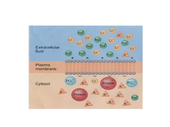

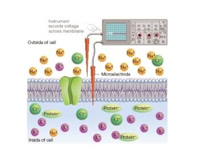
Electrical properties of plasma membranes

• Part A: A basic en: RC circuit, superimposed on an image of a membrane bilayer to show the relationship between the two. Part B: A more elaborate en: RC circuit, superimposed on an image of a membrane bilayer. This RC circuit represents the electrical characteristics of a minimal patch of membrane containing at least one Na and two K channels. Elements shown are the transmembrane voltages produced by concentration gradients in potassium (green) and sodium (blue), The voltage-dependent ion channels that cross the membrane (variable resistors; K=green, Na=blue), the non-voltage-dependent K channel (black), and the membrane capacitance.

Nernest equation

Electro-chemical Equilibrium

Ek+

Concentration of Ions

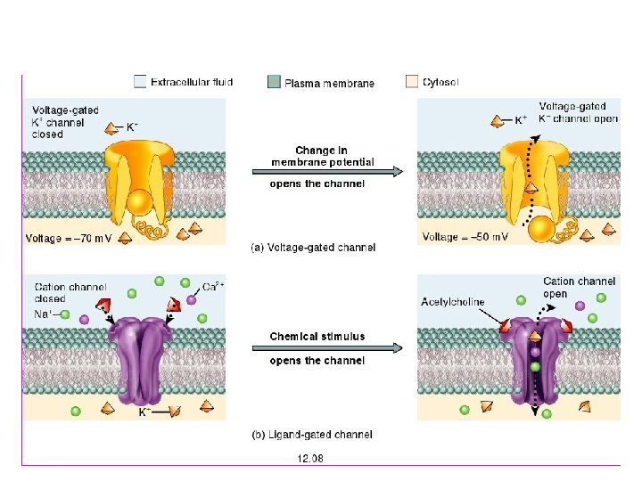
Membrane permeability

Goldman Hodgkin Katz equation

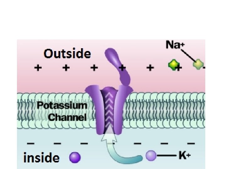
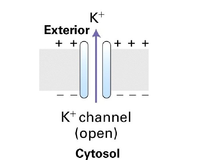
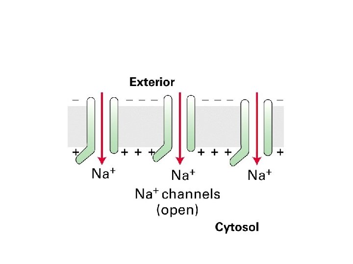
Resting membrane potential • Activity K+ channels • Activity of Na+ channels • Na+/K+ pumps

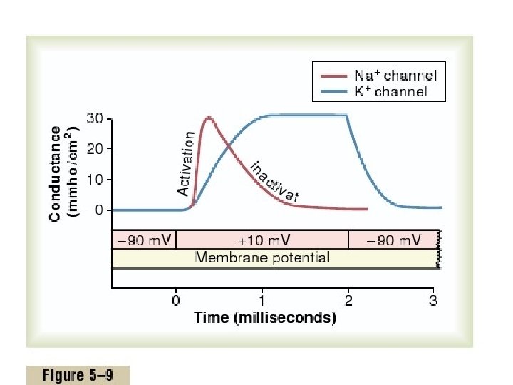
• Na+ and K+ conductance at resting potentials
 • I = ∆V/R • G (conductance)= 1/R")
Conductance of plasma membrane (Ohm’s Law) • I = ∆V/R • G (conductance)= 1/R • I = G. ∆V

Measuring Currents at specific membrane potential

Patch Clamp • Patch still attached to the rest of the cell, as in (A), or detached, as in (B).

Patchclamp Clamp • electronic device is employed to maintain, or “clamp, ” the membrane potential at a set value • recording the ionic current through individual channels

Recording of currents in Patch Clamp

• Na+ and K+ conductance at resting potentials

• Changes in Resting membrane potential

• Changes in Channels activity results in action potential


Ionic currents cause depolarization

Resistance to Ionic currents and activation of channels
- Slides: 29