Transmissive Liquid Crystal Displays From optics of liquid


 12")
 13")
 14")


 • the photonic response of the human eyes P(l)")
 26")
 27")
 Multiplexing Example for STN D 0. 5 T(%) 0. 4 STN")


 90 VR = 3. 15 80 225 70 60")
 270 o Super-Twisted Nematic (STN) 90 80 70 60 50")
 modes • TN, STN: undergo twist in")

 cells 35")

 Normally White: When E-field applied • Γ")


 Normally black operation • Δφ is the twisting angle relative to")


 cells 43")


 splay bend De>0 Classical Fredericks Transition 46")


 V z=0=V z=d=0 Boundary conditions Solve coupled differential equations")

 cells • Also known as the pi cell, or")

 – Separate the primary")
 cell V 0 V 1 (Splay) V 0=0 V 2 (Bend) V")


 ECB cell OCB cell 57")


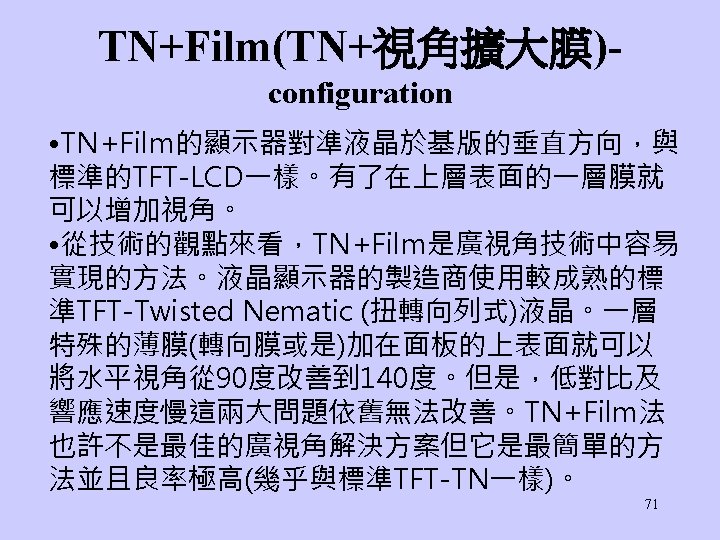

- Configuration 73")

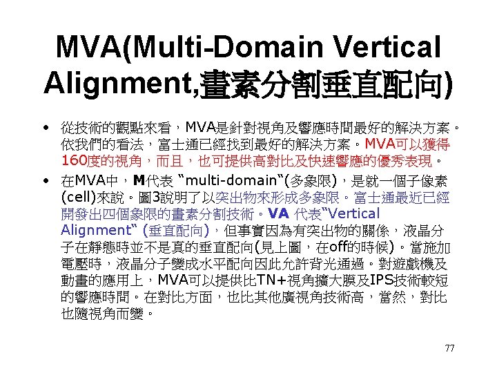
Configuration 富士通所發展的MVA 76")

- Slides: 79
Transmissive Liquid Crystal Displays From optics of liquid crystal display, Chap. 5, 6 P. Yeh and C. Gu 1
Chap. 5 Liquid crystal displays • Most of displays produced recently envolve the use of either TN or STN • The STN was introduced to improve the performance of LCD without the use of TFT. • Here we discuss the principles of operation of various displays. 2
5. 1 twisted nematic displays • The operation of TN based on waveguiding property. 3
5. 1. 2 Transmission properties of field-off state • Using Jones matrix method. • Consider a 90 degree TN cell with front local director // the transmission axis of the polarizer. • The waveguiding is valid only if ψ<<2πΔn d/λ. – φ is the twisting angle. – Known as the limit of slow twist. – Also known as Mauguin(莫吉恩) condition. – For a 90 degree TN, the condition reduces to λ/2<< Δn d. – In general cases when the condition is not satisfied, the output beam is elliptical polarized-reduce the transmission 4
• Consider the eo coordinate system, the input beam is • the output beam is (5. 1 -4) – Mauguin condition equal to φ<< Γ Ex: Dn=0. 23, l=0. 63 mm, φ=p/4 – Output beam ~linearly polarized along the local director(e axis). This explains the waveguiding phenomenon. 5
Normally black mode • In most TN cells, Mauguin condition is not always satisfied. This leads to a series of performance degradation, ex: brightness, contrast, color shift…. . • NB mode: TN cell sandwiches between a pair of parallel polarizer – Input end: LC director // polarizer – Output end: LC director ⊥ polarizer – According eq. (5. 1. 4), the transmission for unpolarized light is given by o component 6
Normally with mode • NW mode: TN cell sandwiches between a pair of cross polarizers • According eq. (5. 1. 4), the transmission for unpolarized light is given by e component 7
Nornally Black mode Dn decreases with voltage Normally White mode Dn decreases with voltage Gooch Tary 1 st minimum principle Voff-bright state, Normally white Voff-dark state, Normally black 8
5. 1. 3 Transmission properties of field-on state -TN mode • The final distribution of the director [θ, φ] as functions of z can be obtained by minimizing the total energy integrated over the LC cell. This require the technique of variational calculus. 9
1. 2. 3. 4. Middle layer director Cell director distribution Subdivide TN director Jones matrix calculation Φ is the total twisting angle 10
11
Twisted Nematic Liquid Crystal Displays: Normally White (e-mode) 12
Twisted Nematic Liquid Crystal Displays: Normally White (o-mode) 13
Twisted Nematic Liquid Crystal Displays: Normally Black (e-mode) 14
Transmission of TN LCDs: Normally Black Dn: varied by applied field first minimum second minimum third minimum V increases 15
Transmission of TN LCDs: Normally White 16 V increases
High Contrast TN LCDs: First Minimum First minimum condition find d for Dn=0. 095 5 mm is a typical cell gap for first minimum displays 17
Contrast at normal incidence Contrast ratio contrast Viewing angles 18
• NB: limited contrast ratio, due to the slightly elliptical output light. • NW: high contrast ratio, because the homeotropically aligned LCs at high voltage. 19
Gray scale inversion 20
21
Isotransmittance Viewing Diagrams: Normally Black TN LCD V=0 Volts V=2. 10 Volts V=5. 49 Volts Reference: Yeh and Gu, Optics of Liquid Crystal Displays 22
Isotransmittance Viewing Diagrams: Normally White TN LCD V=0 Volts V=2. 10 Volts V=5. 49 Volts Reference: Yeh and Gu, Optics of Liquid Crystal Displays 23
Transmitted luminance • The transmission of a TN cell depends on the wavelength of light. • The integrated transmission luminance is obtained by integrating the transmission function T(l) with the photonic response of the human eyes P(l) and the illuminat spectral distribution D(l). 24
• transmission function T(l) • the photonic response of the human eyes P(l) • the illuminat spectral distribution D(l). 25
Super-Twisted Nematic (STN) 26
Super-Twisted Nematic (STN) 27
Super-Twisted Nematic (STN) Multiplexing Example for STN D 0. 5 T(%) 0. 4 STN LCD 0. 3 0. 2 0. 1 VTH 1 2 3 4 5 V Notice the very steep threshold Medium resolution is possible 28
Threshold of STN Define nematic director Calculate the elastic free energy Express elastic free energy in terms of q and f Calculate the electric field contribution to free energy, Dz is displacement 29
Threshold of STN And taking the tilt angle, qo, to be zero. f. T (twist angle) 90 o 180 o 270 o 360 o d/P (gap/pitch) 0. 25 0. 50 0. 75 1. 00 VTH (volts) 1. 10 1. 63 2. 20 2. 70 30
270 o Super-Twisted Nematic (STN) 90 VR = 3. 15 80 225 70 60 180 VR = 2. 04 50 135 40 30 90 20 45 10 0 VR = 1. 83 VR = 0. 11 0 0. 2 0. 4 0. 6 z/L 0. 8 1 Twist Angle f (Degrees) Tilt Angle q (Degrees) 270 0 31 q f
Midlayer tilt angle (deg) 270 o Super-Twisted Nematic (STN) 90 80 70 60 50 270 o STN 40 30 20 10 0 VON VOFF 0. 5 1 1. 5 2 2. 5 Reduced Voltage 3 32
5. 3 nematic liquid crystal display (NLCD) modes • TN, STN: undergo twist in the cell, displays show asymmetric viewing characteristics. Birefringence phase compensation for improving viewing characteristics is difficult. • Now we consider parallel aligned cell, vertical aligned cell and bend aligned cell. 33
TN LCDs Twist angle, complex Wavelength insensitive 34
5. 3. 1 parallel aligned (PA) cells 35
Parallel Aligned Cells x y 36
Vertical switching (E-field perpendicular to LC layer) Normally White: When E-field applied • Γ is chosen to be odd integral of π, usually the lowest order of Γ is usually chosen for the best viewing characteristics at large view angle. • This mode of switching is sometimes referred to as the electrically controlled 37 birefringence mode (ECB-LCD).
Normally black • In the field-off state, LC cell behaves like a half -wave plate. 38
• TN- LCD is less sensitive to wavelength variation that of N -LCDs. • Because TN-LCD is a result of waveguiding in the field-off state, but N-LCDs the transmission is based on polarization interference, which is often sensitive to wavelength. 39
In-plane switching (IPS) Normally black operation • Δφ is the twisting angle relative to the transmission axis of the polarizer due to the applied field. 40
In-Plane Switching 41
• The transmission is sensitive to wavelength. • For IPS LCDs to respond uniformly to all wavelength, pixels with different colors need to have different cell gaps. • Variation of birefringence is small. 42
5. 3. 2 vertical aligned (VA) cells 43
Rubbing direction 44
Backflow effect in LC devices 45
E E Twist (T-Mode) splay bend De>0 Classical Fredericks Transition 46
Backflow Effect in LC Devices TN CHLC 47
ECB-Backflow Effects • S and B deformations are always accompanied by a macroscopic flow of liquid crystal with velocity V=(V(Z), 0, 0), due to a change in position of the centers of gravity of the molecule. (reorientation of molecules out of plane) • The pure T mode is not accompanied by backflow because it is not accompanied by change in centers of gravity. 48
ECB-Backflow Effects Tough Problem: V(z) V z=0=V z=d=0 Boundary conditions Solve coupled differential equations 49
ECB-Backflow Effects For small angles g 1* is effective rotation viscosity ai are the Leslie viscosity coefficients 50
5. 3. 3 bend-aligned (BA) cells • Also known as the pi cell, or optically compensated bend (OCB) mode cell • Originally proposed by Bos and Koehler/Beran. • Fastest response time among nematic LC modes, TN, STN, IPS, MVA, . • w/o backflow • Suitable to Moving picture • Color sequential application 51
Slow Response Time Image blurring http: //www. cmo. com. tw 52
Color Sequential LCDs • Basic concept of color sequential (CS) – Separate the primary colors in temporal domains (not in spatial domains) • Requirement: fast response LC (> 500 Hz) to avoid color breakup 53
OCB (Pi) cell V 0 V 1 (Splay) V 0=0 V 2 (Bend) V 1=Vc (Homeotropic) V 2>>Vc Fast switching Symmetric view A critical field for splay bend transition P. J. Bos et al. MCLC, 113, 329 (1984); Uchida, SID 25, 927 (1994) 54
l/2 55
56
Fast response (w/o backflow) ECB cell OCB cell 57
5. 4 polymer dispersed liquid crystal displays ne~np 58
59
5. 6 projection displays 60
61
6. 3 optical throughput of TFT-LCDs • 6. 3. 1 polarizer – A beam of unpolarized light suffers 50% energy loss due to a perfect polarizer. – In practice, sheet polarizers are used for LCDs. – Commercially available polarizeer materials such as HN 22, HN 38 S and HN 42 HE are used. – They are made of stretched PVA (polyvinyl alcohol) films consisting of highly concentrated iodine dyes. – The transmission of polarizer for LCDs is ~45% or less for visible wavelength. – Ex: HN 42 HE ~42%, the deviation of 8% from perfect polarizer is due to residual absorption for the transmission polarization. 62
63
Cholesteric liquid crystal polarizer RHC LHC 64
Reflectivity of Cholesteric LC Displays Theory Experiment 65
6. 3. 2 color filter • Color filters: dyed gelatin, dyed polyimide, and color inks. • Dyed gelatin is by far the most widely used material. • Other types shown in the next page. 66
67
69
70
72
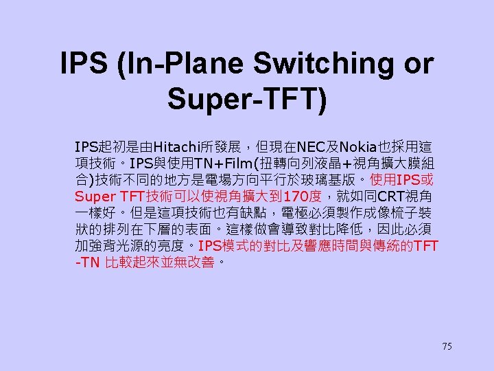
IPS (In-Plane Switching or Super-TFT)- Configuration 73
In-Plane Switching Conventional Twisted Nematic In-Plane Switching Mode 74
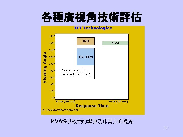
MVA(Multi-Domain Vertical Alignment, 畫素分割垂直配向)Configuration 富士通所發展的MVA 76
Optical compensators for LCDs • From Chap. 9 • Discuss the principle of phase retardation compensation using birefringent thin film to achieve high contrast ratios and gray level stability. 79