Transmission system of Automobile By Dr Vidosh Mahate

Transmission system of Automobile By Dr. Vidosh Mahate HOD-ME SIRTS

Automobile ü Motorized vehicle consisting of four wheels and powered by an internal engine. Automobiles are used to transport people and items from one location to another location. ü The definition of an automobile is a means of transportation that usually has wheels and an engine. A car is an example of an automobile.

Automobile Engineering ü Automobile engineering is the one of the stream of mechanical engineering. It deals with the various types of automobiles, their mechanism of transmission systems and its applications. ü Automobile Engineering is a branch of engineering which deals with designing, manufacturing and operating automobiles. It is a segment of vehicle engineering which deals with motorcycles, buses, trucks, etc. It includes mechanical, electronic, software and safety elements.

Transmission System - It is used to transmit engine torque to the driving wheels to drive the vehicle on the road.

Requirement of Transmission System • To provide for disconnecting the engine from the driving wheels • When engine is running , connect the driving wheels to engine smoothly without shock • Leverage between engine and driving wheels to be varied • Enable the driving wheels to rotate at different speeds. • Provide relative movement between engine and driving wheels

Layout of Transmission System

Transmission System

Clutch Function of clutch • Clutch is used to disengage and engage the engine with rest of the transmission systems. • To disengage while starting the engine and while changing gear ratio. • To engage after starting of the engine and gear shift operation.

Clutch Requirement of Clutch • Transmit maximum torque of the engine. • Engage gradually to avoid sudden jerks. • Dissipate maximum amount of heat. • Damp the vibrations and noise. • Dynamically balanced. • As small as possible. • Easy to operate.

Clutch Unit • Flywheel also acts as a driving member • Pressure plate is connected to clutch cover assembly. • Clutch Cover assembly is bolted to the flywheel. • Clutch springs placed between Pressure plate & Cover plate, press the Pressure plate against the clutch plate. • Thus Clutch plate is squeezed between Flywheel & Pressure plate.

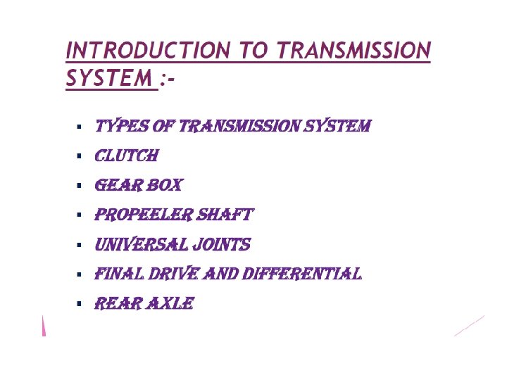
Classification of Clutch • Cone clutch • Flat Plate clutch - Dry or Wet type clutch - No. of friction plates (Single or Multiple) - Actuation mode (Cable or Hydraulic) • Centrifugal clutch

Flat Plate clutch

Clutch Engaged & Disengaged • Clutch is always is in engaged state. • It can be disengaged by pressing of Clutch pedal. Disengagement is effected by non - contact of Clutch plate both with Flywheel face & Pressure plate face. • Frictional heat is dissipated by openings present in Clutch housing & Cover

Clutch Material

Gear Box
")
Gear Box • Gear box varies the leverage (speed ratio & hence torque ratio) between the engine & driving wheels. • It is located between Clutch & Propeller shaft. • It is provided with either 4 speed or 5 speed ratios or more depending on design. • Gear ratio is varied by Gear shift lever.

Manual Transmission - Types Sliding mesh gearbox Constant mesh gearbox Synchromesh Gearbox

Sliding mesh gearbox video of gear boxSliding_Mesh_Gear_Box_2 C_Transmission_system. avi

Constant mesh gearbox

Synchronizers • A device used to bring two adjacent members to the same speed before allowing the sleeve to engage them. • The two elements are friction clutch and toothed clutch. • Lock the positive engagement until speeds are synchronized. • Establish the positive engagement and power flow. • Synchronizer is splined on the shaft Cone on the gear (blue) fits into cone-shaped area in the collar. • Friction between the cone and collar synchronize the collar & gear. • The outer portion of the collar (sleeve) then slides so that the dogteeth engage the gear.

Synchromesh Gearbox video of gear boxManual_Transmission_2 C_How_it_works__3 F. avi

Propeller Shaft Single piece �Two piece � �Front engine �Reduction in rear wheel drive car height (lowering of body) �Crash energy management �Material �Aluminum �steel �Composite (75% carbon, 25% glass-fibre with bonded steel end fittings- Renault) �Cold rolled and seam welded

Propeller Shaft �It propels the vehicle forward, so called propeller shaft �A Propeller Shaft connects a gearbox to a Differential. �It is used to transmit the drive force generated by the engine to the axles. �It is strong enough to handle maximum low gear torque �It is provided with two U-joints to maintain constant velocity and positioning of differential at different plane. �It is provided with a slip joint to take care of the change in length. �Shaft diameter and its thickness decides the torque carrying capacity and angle of operation.
 •")
Universal joints • Designed to eliminate torque and speed fluctuations (constant velocity joints) • If only one universal joint is used, speed fluctuations will not be neutralized. • Two universal joints are used to maintain uniform motion with yoke lung in phase

Universal joints

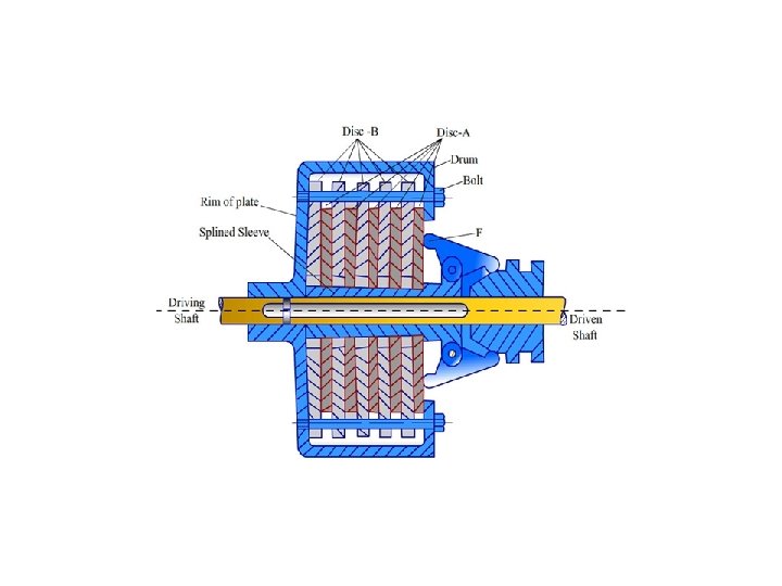
Differential • To transfer the engine power to the wheels • To act as the final gear reduction in the vehicle • To make the wheels to rotate at different speeds while negotiating a turn.

Differential: In Straight Ahead Motion �Input torque is applied to the ring gear, which turns the entire carrier, providing torque to both side gears, which in turn may drive the left and right wheels. �If the resistance at both wheels is equal, the pinion gear does not rotate, and both wheels turn at the same rate.

 encounters resistance, the")
Differential: In a Turn • If the left side gear (red) encounters resistance, the pinion gear(green) rotates about the left side gear, in turn applying extra rotation to the right side gear (yellow).

Axle �Transmits rotary motion and torque from the engine-transmission-driveshaft to the wheels �Changes torsional direction from longitudinal to transverse �Provides speed reduction and torque multiplication �Provides a differential action to permit vehicle cornering �Provides mounting points for suspension and brakes

THANK YOU
- Slides: 34