
Transmission Lines Elements of Electromagnetics Fourth Edition Sadiku



- Slides: 59
Transmission Lines Elements of Electromagnetics Fourth Edition Sadiku 1
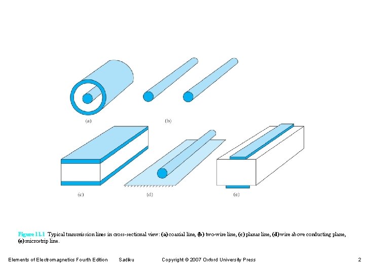
Figure 11. 1 Typical transmission lines in cross-sectional view: (a) coaxial line, (b) two-wire line, (c) planar line, (d) wire above conducting plane, (e) microstrip line. Elements of Electromagnetics Fourth Edition Sadiku Copyright © 2007 Oxford University Press 2
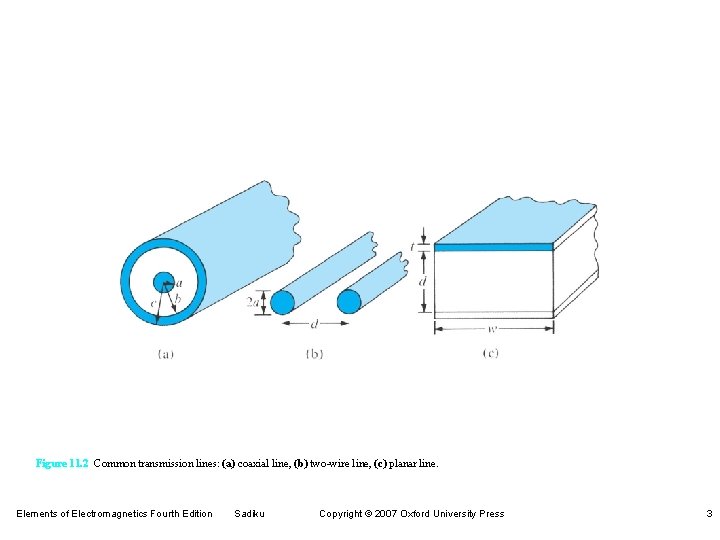
Figure 11. 2 Common transmission lines: (a) coaxial line, (b) two-wire line, (c) planar line. Elements of Electromagnetics Fourth Edition Sadiku Copyright © 2007 Oxford University Press 3
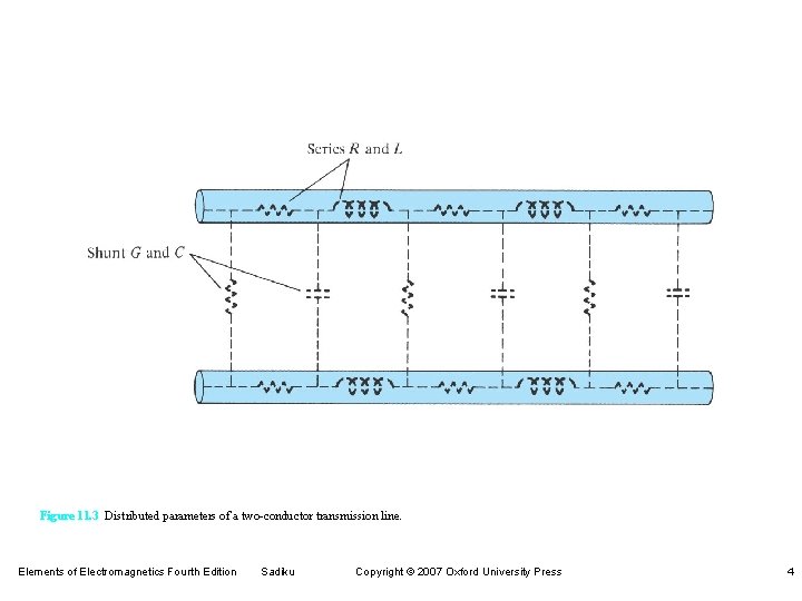
Figure 11. 3 Distributed parameters of a two-conductor transmission line. Elements of Electromagnetics Fourth Edition Sadiku Copyright © 2007 Oxford University Press 4
Figure 11. 4 (a) Coaxial line connecting the generator to the load; (b) E and H fields on the coaxial line. Elements of Electromagnetics Fourth Edition Sadiku Copyright © 2007 Oxford University Press 5
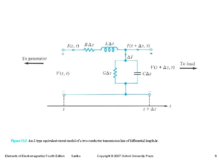
Figure 11. 5 An L-type equivalent circuit model of a two-conductor transmission line of differential length Dz. Elements of Electromagnetics Fourth Edition Sadiku Copyright © 2007 Oxford University Press 6
Figure 11. 6 (a) Input impedance due to a line terminated by a load. (b) Equivalent circuit for finding Vo and Io in terms of Zin at the input. Elements of Electromagnetics Fourth Edition Sadiku Copyright © 2007 Oxford University Press 7
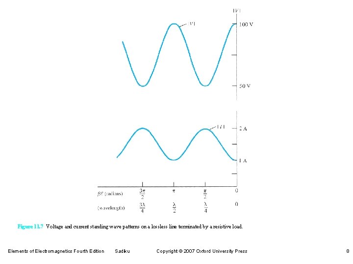
Figure 11. 7 Voltage and current standing wave patterns on a lossless line terminated by a resistive load. Elements of Electromagnetics Fourth Edition Sadiku Copyright © 2007 Oxford University Press 8
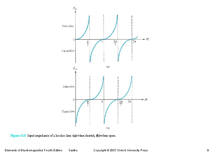
Figure 11. 8 Input impedance of a lossless line: (a) when shorted, (b) when open. Elements of Electromagnetics Fourth Edition Sadiku Copyright © 2007 Oxford University Press 9
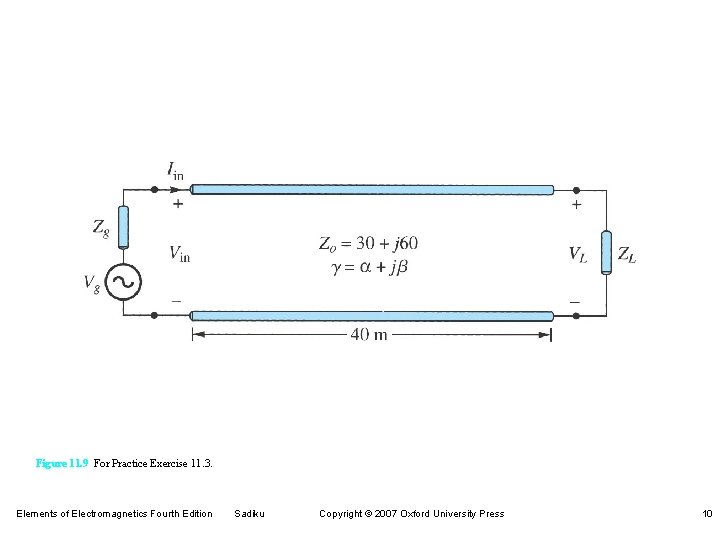
Figure 11. 9 For Practice Exercise 11. 3. Elements of Electromagnetics Fourth Edition Sadiku Copyright © 2007 Oxford University Press 10
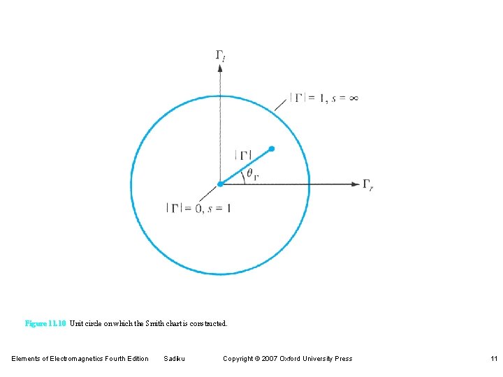
Figure 11. 10 Unit circle on which the Smith chart is constructed. Elements of Electromagnetics Fourth Edition Sadiku Copyright © 2007 Oxford University Press 11
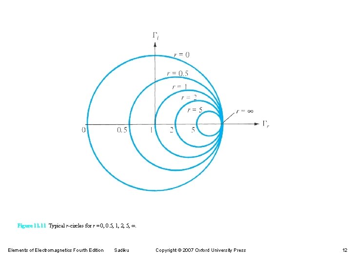
Figure 11. 11 Typical r-circles for r = 0, 0. 5, 1, 2, 5, ∞. Elements of Electromagnetics Fourth Edition Sadiku Copyright © 2007 Oxford University Press 12
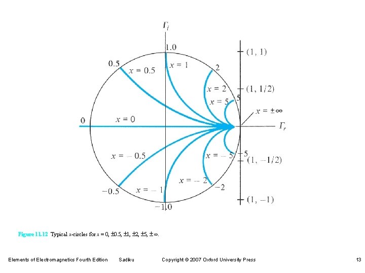
Figure 11. 12 Typical x-circles for x = 0, ± 0. 5, ± 1, ± 2, ± 5, ± ∞. Elements of Electromagnetics Fourth Edition Sadiku Copyright © 2007 Oxford University Press 13
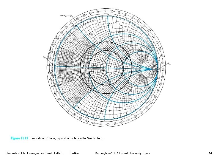
Figure 11. 13 Illustration of the r-, x-, and s-circles on the Smith chart. Elements of Electromagnetics Fourth Edition Sadiku Copyright © 2007 Oxford University Press 14
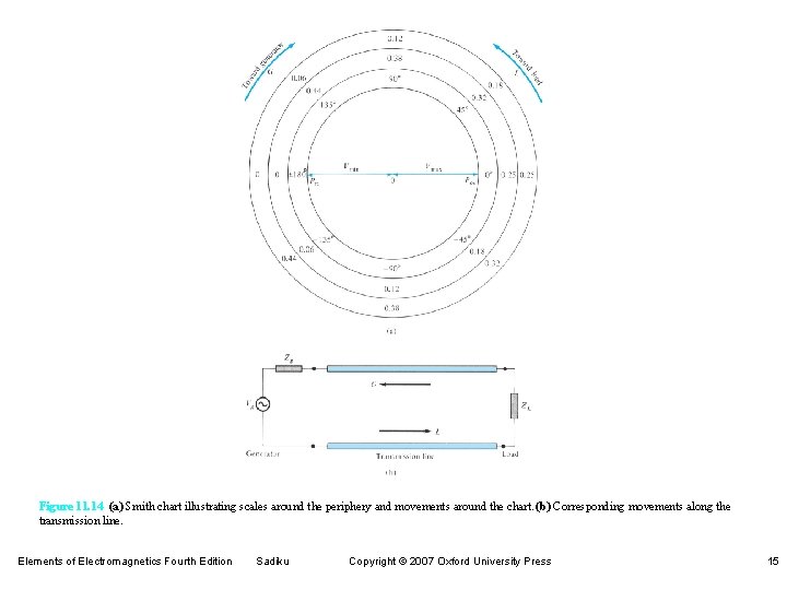
Figure 11. 14 (a) Smith chart illustrating scales around the periphery and movements around the chart. (b) Corresponding movements along the transmission line. Elements of Electromagnetics Fourth Edition Sadiku Copyright © 2007 Oxford University Press 15
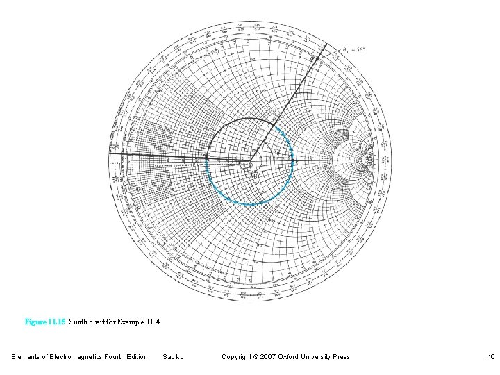
Figure 11. 15 Smith chart for Example 11. 4. Elements of Electromagnetics Fourth Edition Sadiku Copyright © 2007 Oxford University Press 16
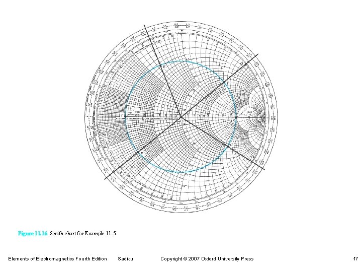
Figure 11. 16 Smith chart for Example 11. 5. Elements of Electromagnetics Fourth Edition Sadiku Copyright © 2007 Oxford University Press 17
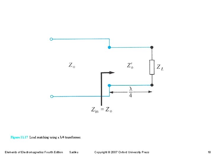
Figure 11. 17 Load matching using a l/4 transformer. Elements of Electromagnetics Fourth Edition Sadiku Copyright © 2007 Oxford University Press 18
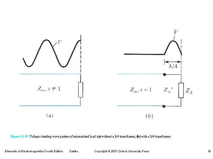
Figure 11. 18 Voltage standing wave pattern of mismatched load: (a) without a l/4 transformer, (b) with a l/4 transformer. Elements of Electromagnetics Fourth Edition Sadiku Copyright © 2007 Oxford University Press 19
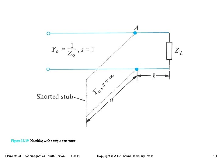
Figure 11. 19 Matching with a single-stub tuner. Elements of Electromagnetics Fourth Edition Sadiku Copyright © 2007 Oxford University Press 20
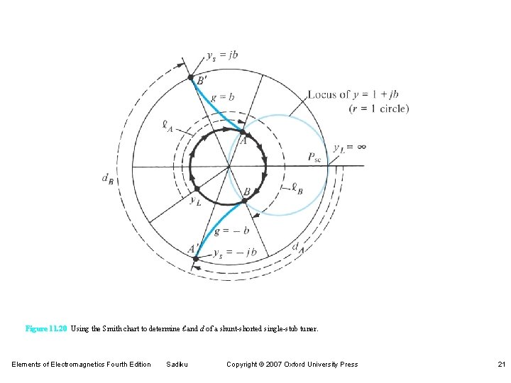
Figure 11. 20 Using the Smith chart to determine ℓ and d of a shunt-shorted single-stub tuner. Elements of Electromagnetics Fourth Edition Sadiku Copyright © 2007 Oxford University Press 21
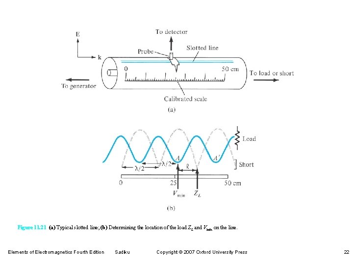
Figure 11. 21 (a) Typical slotted line; (b) Determining the location of the load ZL and Vmin on the line. Elements of Electromagnetics Fourth Edition Sadiku Copyright © 2007 Oxford University Press 22
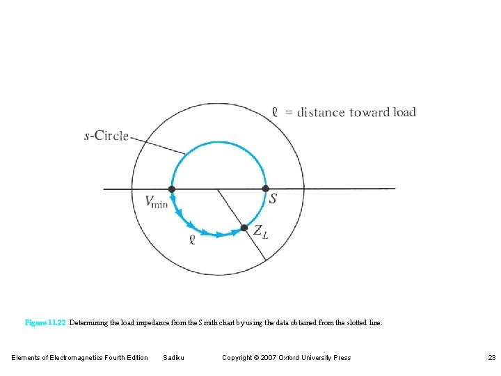
Figure 11. 22 Determining the load impedance from the Smith chart by using the data obtained from the slotted line. Elements of Electromagnetics Fourth Edition Sadiku Copyright © 2007 Oxford University Press 23
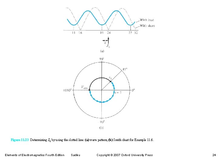
Figure 11. 23 Determining ZL by using the slotted line: (a) wave pattern, (b) Smith chart for Example 11. 6. Elements of Electromagnetics Fourth Edition Sadiku Copyright © 2007 Oxford University Press 24
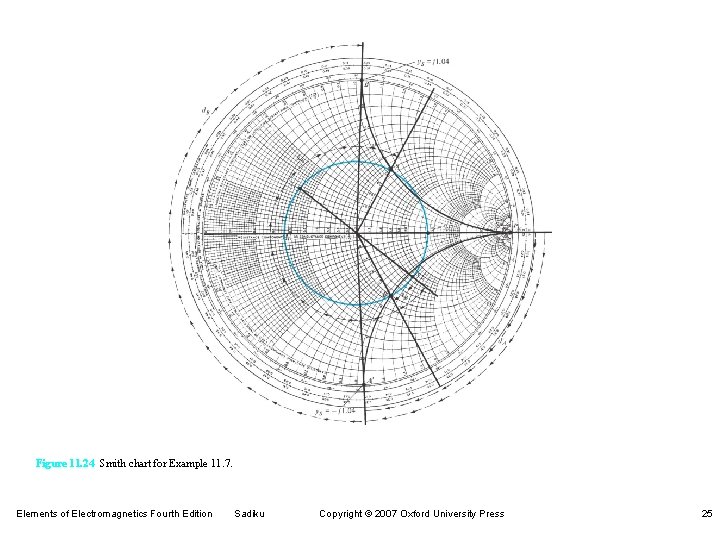
Figure 11. 24 Smith chart for Example 11. 7. Elements of Electromagnetics Fourth Edition Sadiku Copyright © 2007 Oxford University Press 25
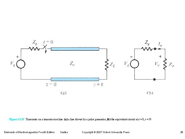
Figure 11. 25 Transients on a transmission line: (a) a line driven by a pulse generator, (b) the equivalent circuit at z = 0, t = 0+. Elements of Electromagnetics Fourth Edition Sadiku Copyright © 2007 Oxford University Press 26
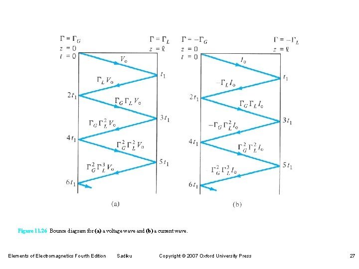
Figure 11. 26 Bounce diagram for (a) a voltage wave and (b) a current wave. Elements of Electromagnetics Fourth Edition Sadiku Copyright © 2007 Oxford University Press 27
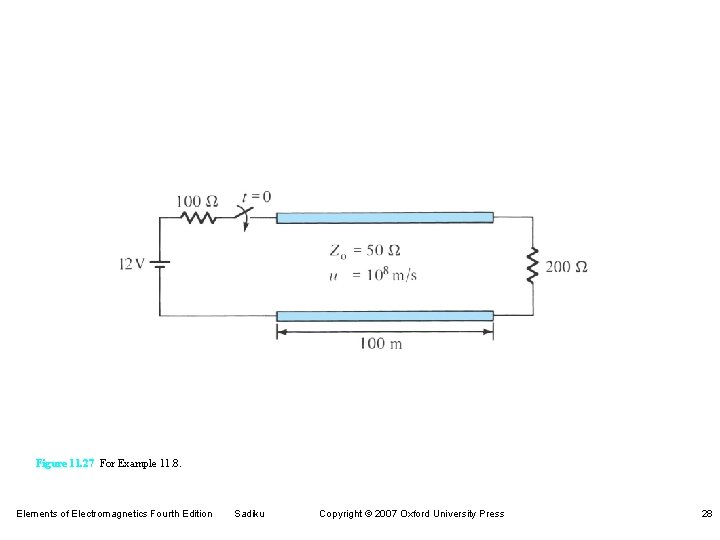
Figure 11. 27 For Example 11. 8. Elements of Electromagnetics Fourth Edition Sadiku Copyright © 2007 Oxford University Press 28
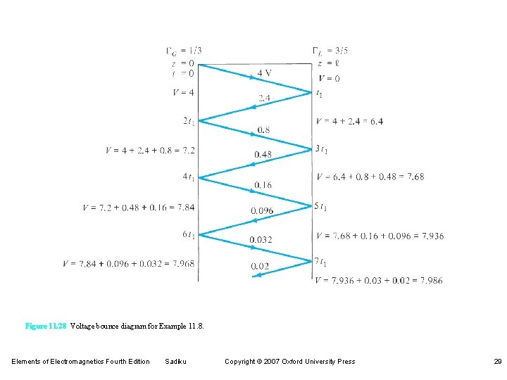
Figure 11. 28 Voltage bounce diagram for Example 11. 8. Elements of Electromagnetics Fourth Edition Sadiku Copyright © 2007 Oxford University Press 29
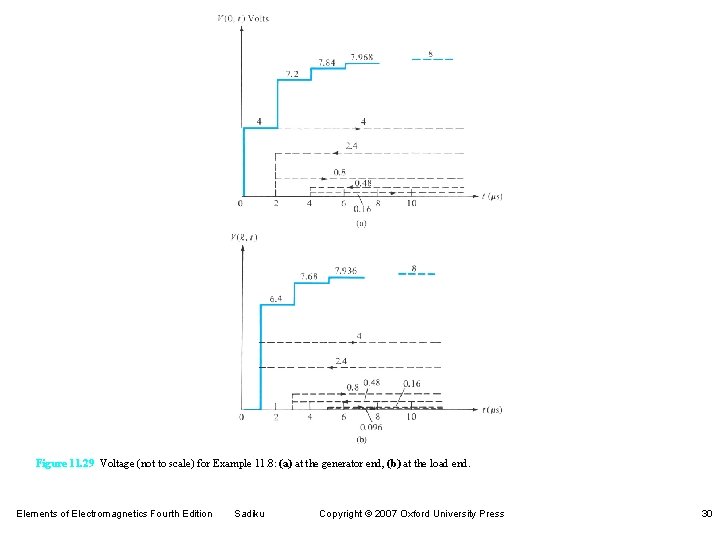
Figure 11. 29 Voltage (not to scale) for Example 11. 8: (a) at the generator end, (b) at the load end. Elements of Electromagnetics Fourth Edition Sadiku Copyright © 2007 Oxford University Press 30
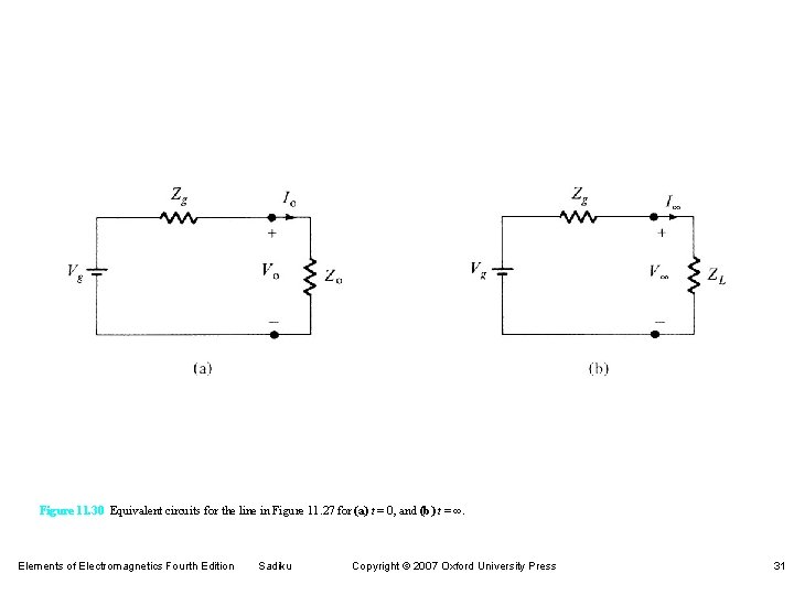
Figure 11. 30 Equivalent circuits for the line in Figure 11. 27 for (a) t = 0, and (b) t = ∞. Elements of Electromagnetics Fourth Edition Sadiku Copyright © 2007 Oxford University Press 31
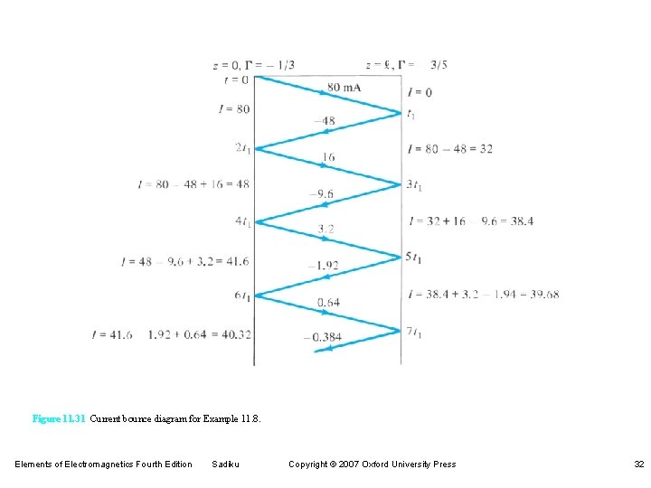
Figure 11. 31 Current bounce diagram for Example 11. 8. Elements of Electromagnetics Fourth Edition Sadiku Copyright © 2007 Oxford University Press 32
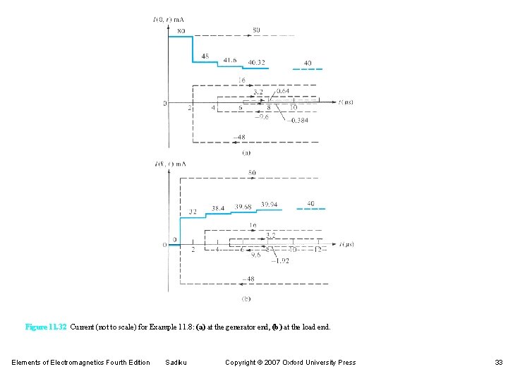
Figure 11. 32 Current (not to scale) for Example 11. 8: (a) at the generator end, (b) at the load end. Elements of Electromagnetics Fourth Edition Sadiku Copyright © 2007 Oxford University Press 33
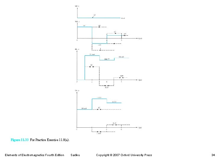
Figure 11. 33 For Practice Exercise 11. 8(a). Elements of Electromagnetics Fourth Edition Sadiku Copyright © 2007 Oxford University Press 34
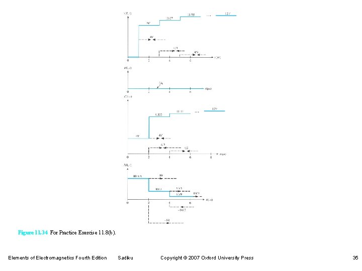
Figure 11. 34 For Practice Exercise 11. 8(b). Elements of Electromagnetics Fourth Edition Sadiku Copyright © 2007 Oxford University Press 35
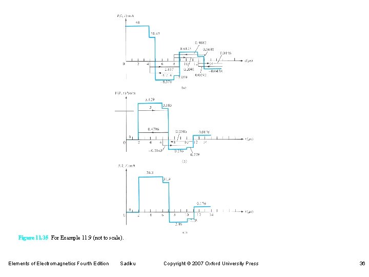
Figure 11. 35 For Example 11. 9 (not to scale). Elements of Electromagnetics Fourth Edition Sadiku Copyright © 2007 Oxford University Press 36
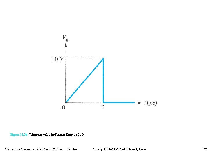
Figure 11. 36 Triangular pulse for Practice Exercise 11. 9. Elements of Electromagnetics Fourth Edition Sadiku Copyright © 2007 Oxford University Press 37
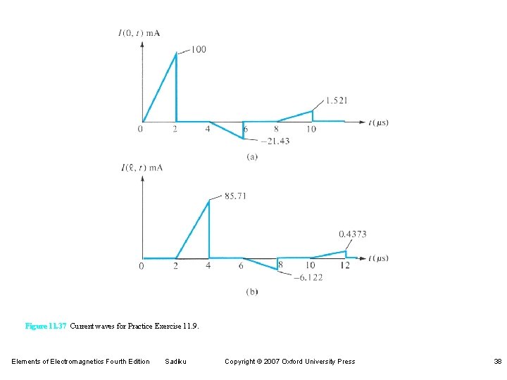
Figure 11. 37 Current waves for Practice Exercise 11. 9. Elements of Electromagnetics Fourth Edition Sadiku Copyright © 2007 Oxford University Press 38
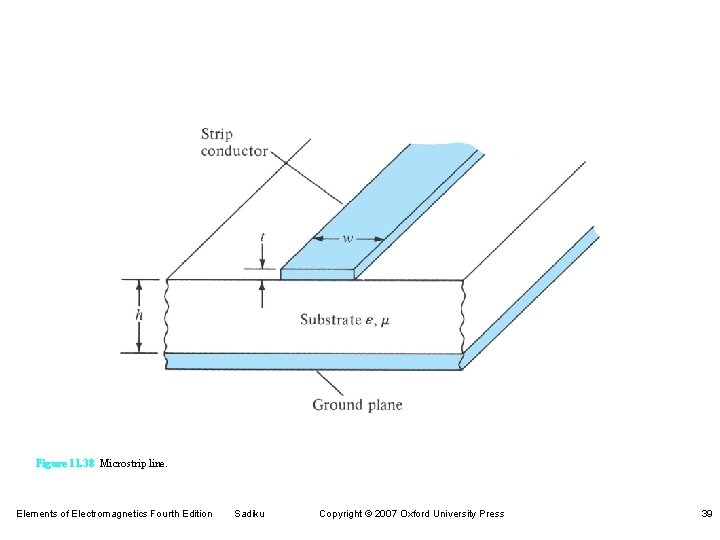
Figure 11. 38 Microstrip line. Elements of Electromagnetics Fourth Edition Sadiku Copyright © 2007 Oxford University Press 39
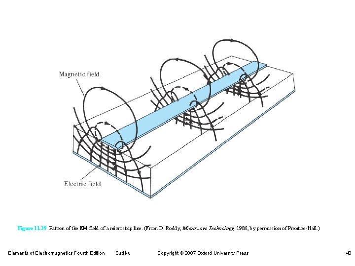
Figure 11. 39 Pattern of the EM field of a microstrip line. (From D. Roddy, Microwave Technology, 1986, by permission of Prentice-Hall. ) Elements of Electromagnetics Fourth Edition Sadiku Copyright © 2007 Oxford University Press 40
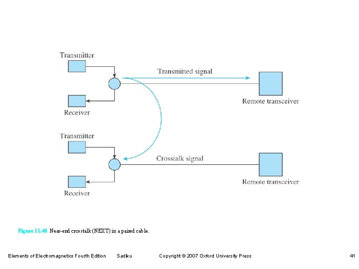
Figure 11. 40 Near-end crosstalk (NEXT) in a paired cable. Elements of Electromagnetics Fourth Edition Sadiku Copyright © 2007 Oxford University Press 41
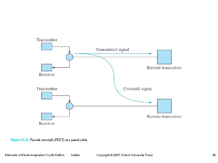
Figure 11. 41 Far-end crosstalk (FEXT) in a paired cable. Elements of Electromagnetics Fourth Edition Sadiku Copyright © 2007 Oxford University Press 42
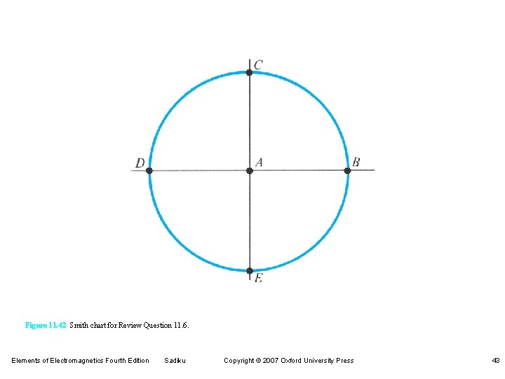
Figure 11. 42 Smith chart for Review Question 11. 6. Elements of Electromagnetics Fourth Edition Sadiku Copyright © 2007 Oxford University Press 43
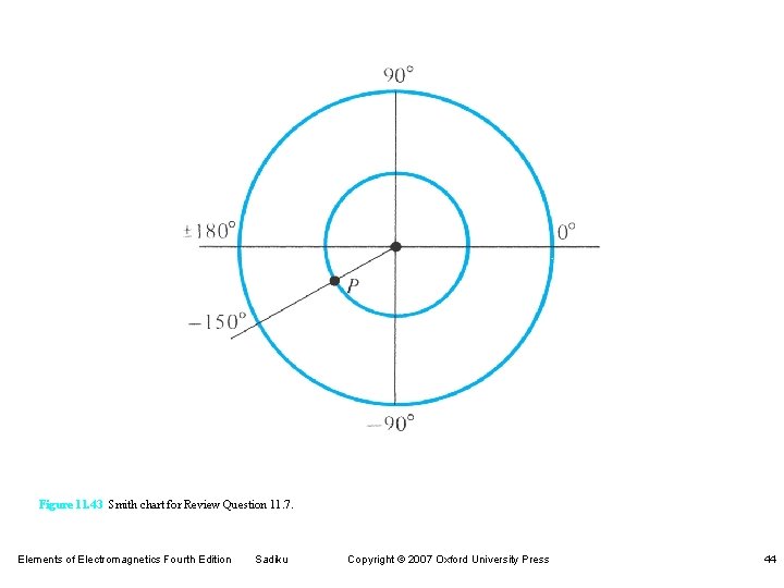
Figure 11. 43 Smith chart for Review Question 11. 7. Elements of Electromagnetics Fourth Edition Sadiku Copyright © 2007 Oxford University Press 44
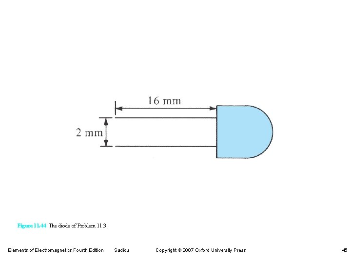
Figure 11. 44 The diode of Problem 11. 3. Elements of Electromagnetics Fourth Edition Sadiku Copyright © 2007 Oxford University Press 45
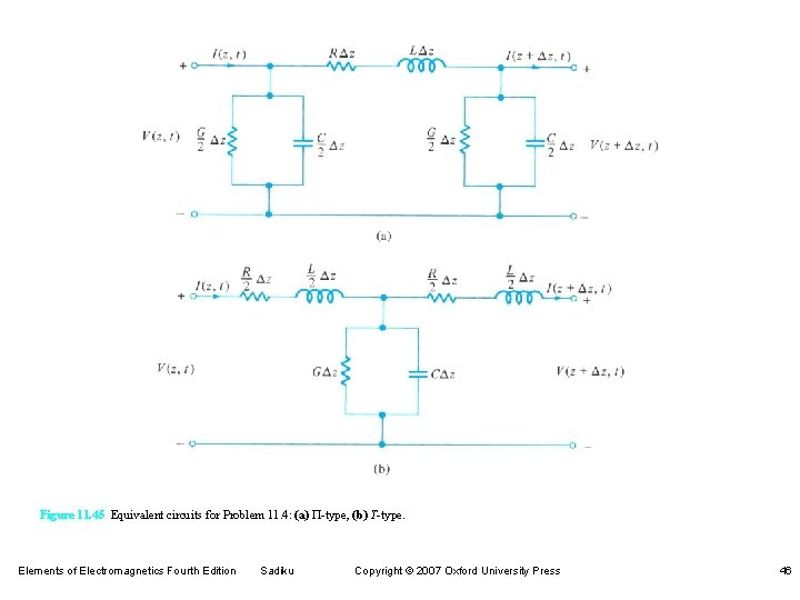
Figure 11. 45 Equivalent circuits for Problem 11. 4: (a) P-type, (b) T-type. Elements of Electromagnetics Fourth Edition Sadiku Copyright © 2007 Oxford University Press 46
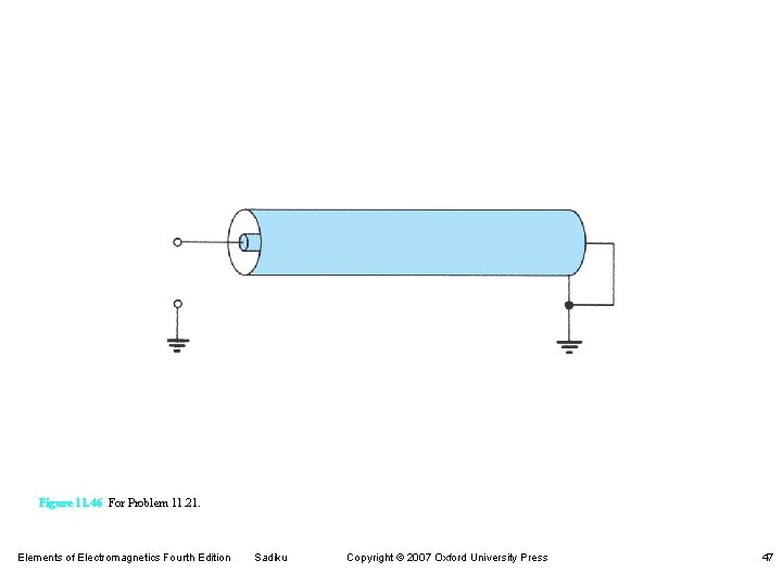
Figure 11. 46 For Problem 11. 21. Elements of Electromagnetics Fourth Edition Sadiku Copyright © 2007 Oxford University Press 47
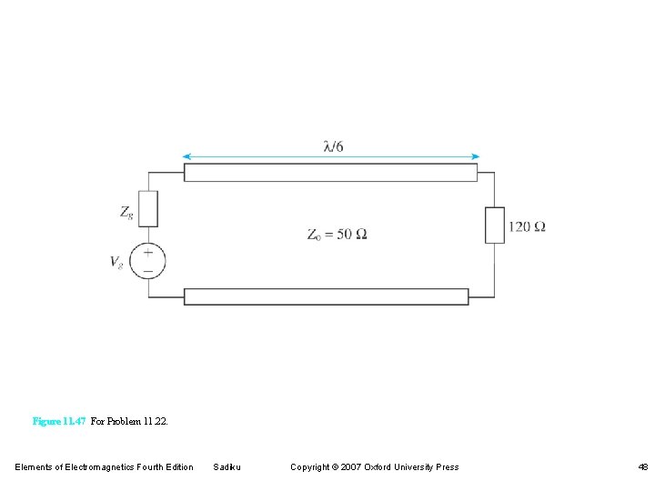
Figure 11. 47 For Problem 11. 22. Elements of Electromagnetics Fourth Edition Sadiku Copyright © 2007 Oxford University Press 48
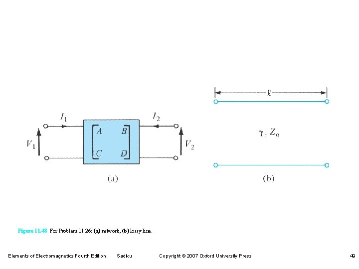
Figure 11. 48 For Problem 11. 26: (a) network, (b) lossy line. Elements of Electromagnetics Fourth Edition Sadiku Copyright © 2007 Oxford University Press 49
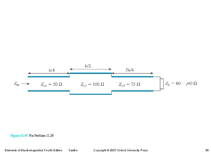
Figure 11. 49 For Problem 11. 29. Elements of Electromagnetics Fourth Edition Sadiku Copyright © 2007 Oxford University Press 50
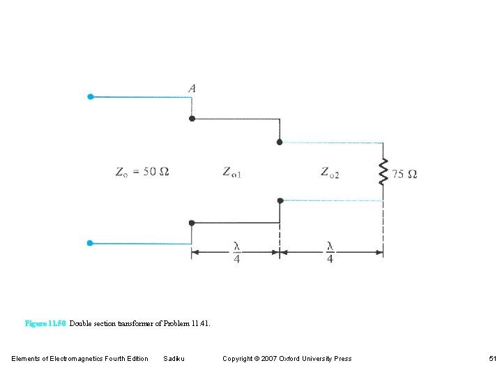
Figure 11. 50 Double section transformer of Problem 11. 41. Elements of Electromagnetics Fourth Edition Sadiku Copyright © 2007 Oxford University Press 51
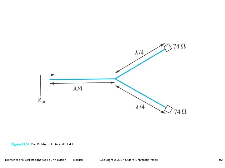
Figure 11. 51 For Problems 11. 42 and 11. 43. Elements of Electromagnetics Fourth Edition Sadiku Copyright © 2007 Oxford University Press 52
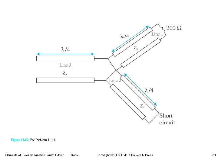
Figure 11. 52 For Problem 11. 44. Elements of Electromagnetics Fourth Edition Sadiku Copyright © 2007 Oxford University Press 53
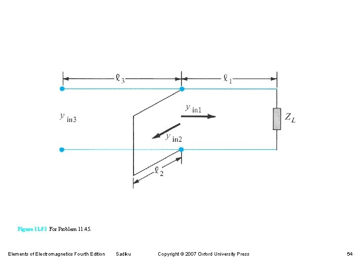
Figure 11. 53 For Problem 11. 45. Elements of Electromagnetics Fourth Edition Sadiku Copyright © 2007 Oxford University Press 54
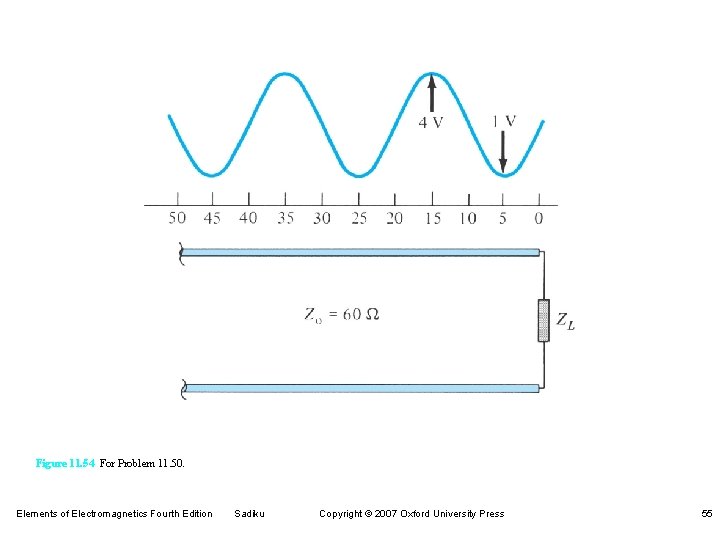
Figure 11. 54 For Problem 11. 50. Elements of Electromagnetics Fourth Edition Sadiku Copyright © 2007 Oxford University Press 55
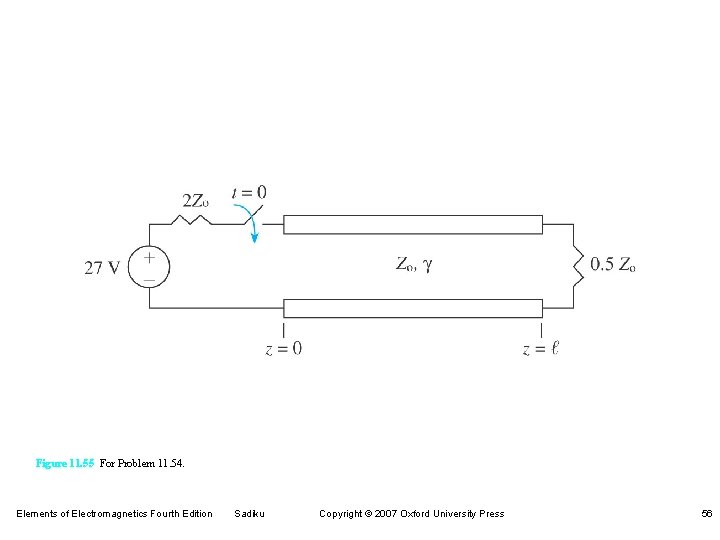
Figure 11. 55 For Problem 11. 54. Elements of Electromagnetics Fourth Edition Sadiku Copyright © 2007 Oxford University Press 56
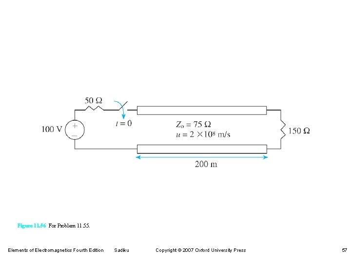
Figure 11. 56 For Problem 11. 55. Elements of Electromagnetics Fourth Edition Sadiku Copyright © 2007 Oxford University Press 57
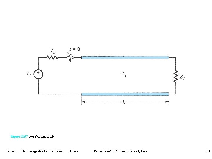
Figure 11. 57 For Problem 11. 56. Elements of Electromagnetics Fourth Edition Sadiku Copyright © 2007 Oxford University Press 58
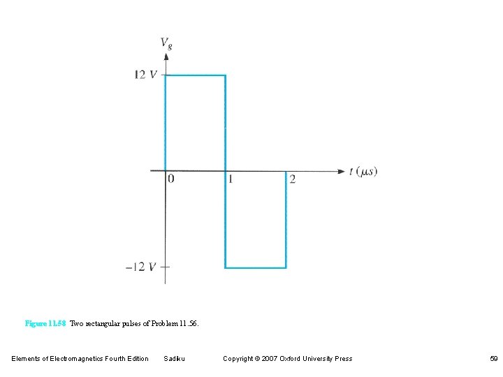
Figure 11. 58 Two rectangular pulses of Problem 11. 56. Elements of Electromagnetics Fourth Edition Sadiku Copyright © 2007 Oxford University Press 59