Transmission line fault detection INTRODUCTION When fault occurs


 { bs 1 = digital. Read(buttonone); bs")
; lcd. print(\"m\"); } else { lcd.")
/1024. 0; buffer=")
; delay(500) ; digital. Write(9, HIGH); delay(500)")
; lcd. print(\"B: \"); lcd. print(\"NF")
; lcd. print(\"Span 2: NF\"); delay (500);")


- Slides: 19
Transmission line fault detection
INTRODUCTION When fault occurs on transmission lines, detecting fault is necessary for power system in order to clear fault before it increases the damage to the power system. When any fault occurs in cable, then it is difficult to locate fault. So, we will move to find the exact location of fault •
main objectives of PROJECT • To design an efficient and robust automatic fault detection and location system for overhead and underground power transmission lines. • To reduce response time needed to rectify and save expensive transformers from damage or theft which usually occurs during longer power outages. • To increase productivity of technical crews since the time needed to locate faults will be minimized. To ensure stability and reliability of the power supply system in the country to boost economic growth •
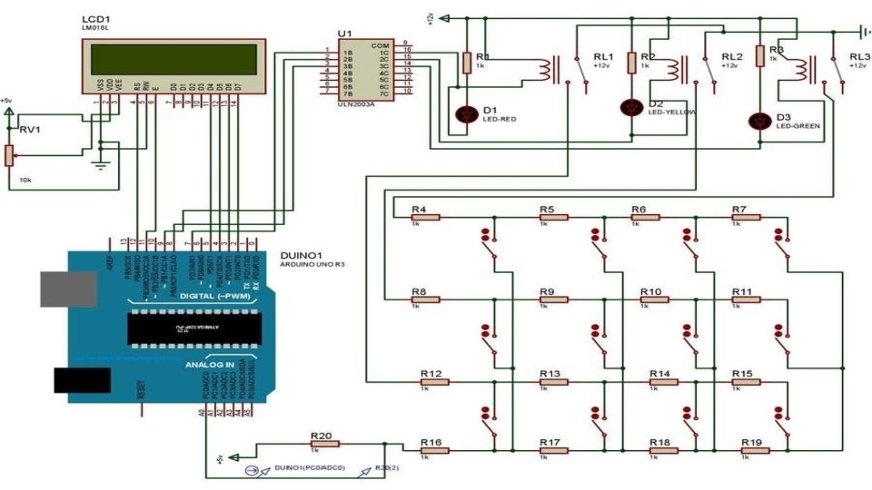
Working Principle In this paper, we have two cables i. e. underground cable and overhead cable. We make the fault in cables by switching the buttons. • The project uses four sets of resistances in series representing cables i. e. R 4, R 5, R 7, R 8 and R 9, R 10, R 11, R 12 then R 13, R 14, R 15, R 16 then R 17, R 18, R 19, R 20. One set for each phase. • Each series resistors represent the resistance of the underground cable for a specific distance (200 m), 3 relays are used to common point of their contacts are grounded while the points of input resistance R 9, R 13, R 17 are connected to the 3 phase supply as an input, the common point of R 6 & R 4 is connected to pin of A 0 which is ADC (Analog to digital) pint of Arduino. •
Two switches are connected with Arduino digital pin 0 and 1 for overhead • cable, they are pulling down by the 10 K resistor while any of the 12 switches (representing as fault switches) are operated they impose conditions like line to ground (LG), line to line (LL), line to line(3 L) fault as per the switch operation. The program while executed continuously scans by operating the relays in sequence of 1 sec interval. •
Thus, any point while driven to GND through the common contact point of the 3 relays, the current flows and if any of the fault switch pressed the fault is occurs, depending on the created fault. Thus, the voltage drop at the analog to digital (ADC) pin varies depending on the current flow which is inversely proportional to the resistance value representing the length of cable in meters, This varying voltage is fed to the ADC to develop an 8 -bit data to the microcontroller Analog port. •
Program while executed displays an output in the LCD display depend upon the distance of the fault occurring in meter’s When no fault occurs in underground and overhead line the LCD display shows that: R: NF, Y: NF, B: NF, span 1: NF, span 2: NF When the fault occurs in R phase on 100 meters then LCD display : • R: 100 m, Y: NF, B: NF, span 1: NF, span 2: NF •
CODE
• • • • • int analog. Pin= 0; int raw 1, raw 2, raw 3= 0; int Vin= 5; float Vout, buffer = 0; int R 1= 1000; int R 2, R 3, R 4= 0; #include <Liquid. Crystal. h> Liquid. Crystal lcd (12, 11, 5, 4, 3, 2); const int buttonone = 0; const int buttontwo = 1; int bs 1, bs 2 = 0; void setup () { pin. Mode (7, OUTPUT); pin. Mode (8, OUTPUT); pin. Mode (9, OUTPUT); pin. Mode (buttonone, INPUT); pin. Mode (buttontwo, INPUT); lcd. begin(2 , 16) ; }
• • • • void loop() { bs 1 = digital. Read(buttonone); bs 2 = digital. Read(buttontwo); lcd. clear(); digital. Write(7, HIGH); delay(500) ; raw 1= analog. Read(A 0); delay(500) ; if(raw 1){ buffer= raw 1 * Vin; Vout= (buffer)/1024. 0; buffer= (Vin/Vout) -1; R 2= R 1 * buffer; lcd. set. Cursor(0, 0); lcd. print("R: ");
• • • • lcd. print(R 2); lcd. print("m"); } else { lcd. set. Cursor(0, 0); lcd. print("R: "); lcd. print("NF "); } digital. Write(7, LOW); delay (500); digital. Write(8, HIGH); delay (500); raw 2= analog. Read(A 0); delay (500); if(raw 2) {
• • • • buffer= raw 2 * Vin; Vout= (buffer)/1024. 0; buffer= (Vin/Vout) -1; R 3= R 1 * buffer; lcd. set. Cursor(8, 0); lcd. print("Y: "); lcd. print(R 3); lcd. print("m"); } else { lcd. set. Cursor(8, 0); lcd. print("Y: "); lcd. print("NF "); • }
• • • • digital. Write(8, LOW); delay(500) ; digital. Write(9, HIGH); delay(500) ; raw 3 = analog. Read(A 0); delay(500) ; if(raw 3){ buffer= raw 3 * Vin; Vout= (buffer)/1024. 0; buffer= (Vin/Vout) -1; R 4= R 1 * buffer; lcd. set. Cursor(0, 1); lcd. print("B: "); lcd. print(R 4); lcd. print("m"); } else
• • • { lcd. set. Cursor(0, 1); lcd. print("B: "); lcd. print("NF "); } digital. Write(9, LOW); delay(500) ; if (bs 1 == HIGH) { lcd. clear(); lcd. set. Cursor(0, 0); lcd. print("Span 1: NF"); (500) delay}; • • else{ lcd. clear(); lcd. set. Cursor(0, 0); lcd. print("Span 1: OC"); delay(500) ; } if (bs 2 == HIGH) { lcd. clear();
• • • lcd. set. Cursor(0, 1); lcd. print("Span 2: NF"); delay (500); } else { lcd. clear(); lcd. set. Cursor(0, 1); lcd. print("Span 2: OC"); delay(500); }}
RESULT This paper represents that the fault location scheme for transmission systems consisting of an overhead line and underground cable. The Arduino system has the ability to locate the fault whether it is in the overhead line or in the underground power cable. In addition to, the proposed scheme gives an accurate estimation of the fault resistance at fault location •
CONCLUSION This paper proposed a fault location scheme for transmission systems • consisting of an overhead line in combination with an underground power cable. In this method, the short circuit fault at a particular distance in the underground cable can be located using simple concepts of OHM’s law enables to rectify fault efficiently feeder end in meters by using Arduino. For this we use simple concept of OHM’s law so fault can be easily detected and repaired. By using Arduino controller, we can find out exact fault location. Once faults occur in the cable, the display unit displays the exact fault location that displays which phase is affected in the cable and how long it’s affected.
THE END