Transistor equivalent circuits and models Equal vs Equivalent


- Slides: 22
Transistor equivalent circuits and models
• Equal vs. Equivalent – To analyze transistor circuits easily n rapidly – Discuss here – small signal: in which the AC input signal voltage and currents are in the order of +/10% of Q-point V or I.
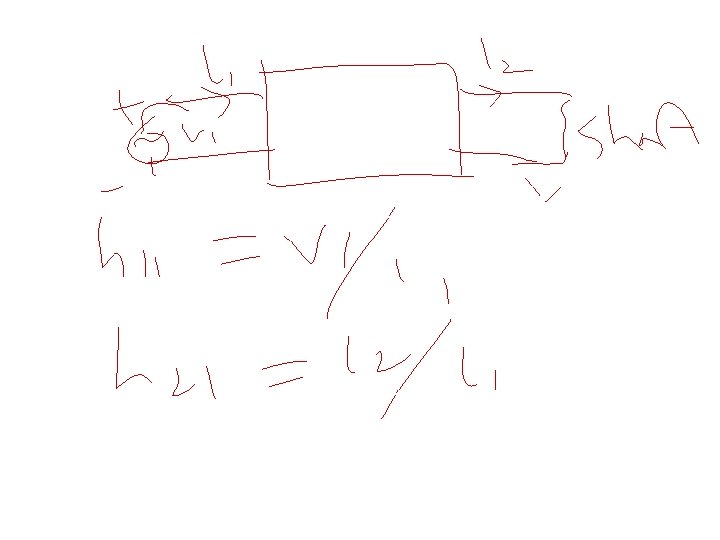
• 4 h-parameters or constants • h – hybrid
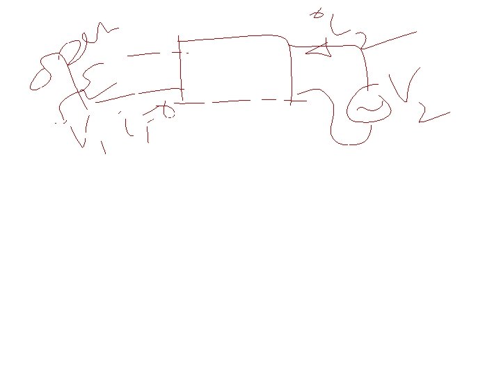
DC eqv. CB circuit • Ideal trans. alpha = 1 Ic = Ie Emitter diode F. Biased ideal diode Collector diode acts as a current source Draw: 56. 1/2: draw for NPN and PNP --- CB.
AC eqv. CB ckt. • For small i/p AC signals, • Emitter diode does not rectify, it offers resistance called ac resistance
• T-model – ~not used now • F. 56. 33
h-parameters? • 4 h parameters or constants for 2 -port network. • h 11, h 12, h 21, h 22 • hybrid? – mixture of different items; different units or just ratio.
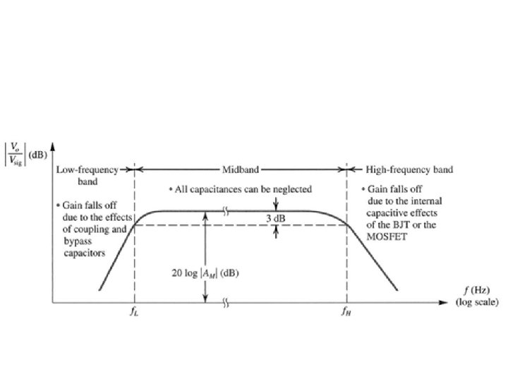
Freq. response
Frequency response of amplifiers • �Midband: • �The frequency range of interest for amplifiers • �Large capacitors can be treated as short circuit and small capacitors can be treated as open circuit • �Gain is constant and can be obtained by small-signal analysis
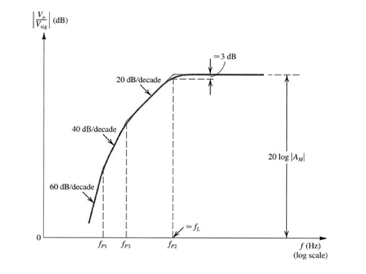
Low-frequency band: • �Gain drops at frequencies lower than f. L • �Large capacitors can no longer be treated as short circuit • �The gain roll-off is mainly due to coupling and by-pass capacitors
LOW FREQUENCY • At low frequency range, the gain falloff due to coupling capacitors and bypass capacitors. • As signal frequency , the reactance of the coupling capacitor, XC - no longer behave as short circuits. 13
High-frequency band: • �Gain drops at frequencies higher than f. H • �Small capacitors can no longer treated as open circuit • �The gain roll-off is mainly due to parasitic capacitances of the MOSFETs and BJTs
Amplifier gain vs frequency Midband range Gain falls of due to the effects of stray capacitance and transistor capacitance effects Gain falls of due to the effects of CC and CE 16
Gain & frequencies • Gain-bandwidth product : constant value of the product of the voltage gain and the bandwidth. • Unity-gain frequency : the frequency at which the amplifier’s gain is 1 18
High Frequency Roll-off of Amplifier • As frequency of operation increases, the gain of amplifier decreases. CH 11 Frequency Response 19
Example: Human Voice I Natural Voice Telephone System • Natural human voice spans a frequency range from 20 Hz to 20 KHz, however conventional telephone system passes frequencies from 400 Hz to 3. 5 KHz. Therefore phone conversation differs from face-to-face conversation. CH 11 Frequency Response 20
Example: Video Signal High Bandwidth Low Bandwidth • Video signals without sufficient bandwidth become fuzzy as they fail to abruptly change the contrast of pictures from complete white into complete black. CH 11 Frequency Response 21
Typical Frequency Response Lower Corner CH 11 Frequency Response Upper Corner 22

 Advantages of parallel circuit over series circuit
 Bjt small signal model
 Cmos leakage current
 What is equal sharing and equal grouping
 Thevenin and norton equivalent circuits
 Equal height equal light
 Taku graphics
 Side opposite equal angle
 Equal area vs equal angle stereonet
 Ac equivalent circuit of diode
 Schema equivalent transistor
 Rajeev balasubramonian
 Programmable unijunction transistor
 Semi-modals
 Networks and graphs circuits paths and graph structures
 Euler and hamilton circuits
 Pros and cons of parallel circuits
 Datagram approach and virtual circuit approach
 Types of circuits and ohm's law ch 7.1 answers
 Complete circuit and incomplete circuit
 Difference between series and parallel circuits
 How do series and parallel circuits differ?
 Dc
Dc


