Transient Excitation of FirstOrder Circuits 1 2 3

 Linear Time.")

 • Any first-order circuit can be reduced to a Thévenin (or Norton)")


 • For t > 0, the circuit reduces")
 + Io Ro L R v –")
 • Define the")


 C capacitance is defined by")
 |( i C voltage time")
 i C + i R This is")


 • For t > 0, the circuit reduces")
 i Vo + + Ro C v")
 • Define the")


 starts at Vout(0) and goes to Vin asymptotically. • The difference")


 in an")

, the current or voltage just after")


- Slides: 39
Transient Excitation of First-Order Circuits 1. 2. 3. 4. 5. What is transient excitation and why is it important? What is a first-order circuit? What are “natural response” and “step response”? Transients in RL circuits (briefly) Transients in RC circuits application to computer circuits
Types of Circuit Excitation Linear Time. Invariant Circuit Steady-State Excitation (DC Steady-State) Linear Time. Invariant Circuit Sinusoidal (Single. Frequency) Excitation AC Steady-State OR Digital Pulse Source Linear Time. Invariant Circuit Transient Excitation
First-Order Circuits • A circuit that contains only sources, resistors and an inductor is called an RL circuit. • A circuit that contains only sources, resistors and a capacitor is called an RC circuit. • RL and RC circuits are called first-order circuits because their voltages and currents are described by first-order differential equations. R i i L vs – + vs R C
Review (Conceptual) • Any first-order circuit can be reduced to a Thévenin (or Norton) equivalent connected to either a single equivalent inductor or capacitor. RTh RN L VTh – + IN C – In steady state, an inductor behaves like a short circuit – In steady state, a capacitor behaves like an open circuit
• The natural response of an RL or RC circuit is its behavior (i. e. , current and voltage) when stored energy in the inductor or capacitor is released to the resistive part of the network (containing no independent sources). • The step response of an RL or RC circuit is its behavior when a voltage or current source step is applied to the circuit, or immediately after a switch state is changed.
Natural Response of an RL Circuit • Consider the following circuit, for which the switch is closed for t < 0, and then opened at t = 0: t=0 Io Ro i L + R v – Notation: 0– is used to denote the time just prior to switching 0+ is used to denote the time immediately after switching • The current flowing in the inductor at t = 0– is Io
Solving for the Current (t 0) • For t > 0, the circuit reduces to i Io Ro L + R v – • Applying KVL to the LR circuit yields first-order D. E. : • Solution: = I 0 e-(R/L)t
Solving for the Voltage (t > 0) + Io Ro L R v – • Note that the voltage changes abruptly (step response): v (0 ) = 0 for t > 0, v(t ) = i. R = I o Re + Þ v(0 ) = I 0 R ( R / L ) t
Time Constant t • In the example, we found that (sec) • Define the time constant – At t = t, the current has reduced to 1/e (~0. 37) of its initial value. – At t = 5 t, the current has reduced to less than 1% of its initial value.
Transient response of RC circuits and application to computer circuits driven by binary voltage pulses
Capacitors and Stored Charge • So far, we have assumed that electrons keep on moving around a circuit. • Current doesn’t really “flow through” a capacitor. No electrons can go through the insulator. • But, we say that current flows through a capacitor. What we mean is that positive charge collects on one plate and leaves the other. • A capacitor stores charge. Theoretically, if we did a KCL surface around one plate, KCL could fail. But we don’t do that. • When a capacitor stores charge, it has nonzero voltage. In this case, we say the capacitor is “charged”. A capacitor with zero voltage has no charge differential, and we say it is “discharged”.
Capacitors in circuits • If you have a circuit with capacitors, you can use KVL and KCL, nodal analysis, etc. • The voltage across the capacitor is related to the current through it by a differential equation instead of Ohm’s law.
CAPACITORS +V |( i(t) C capacitance is defined by
Charging a Capacitor with a constant current + V(t) |( i C voltage time
Discharging a Capacitor through a resistor V(t) i C + i R This is an elementary differential equation, whose solution is the exponential: Since:
Voltage vs time for an RC discharge Voltage Time
Natural Response of an RC Circuit • Consider the following circuit, for which the switch is closed for t < 0, and then opened at t = 0: Vo + Ro C t=0 + v – R Notation: 0– is used to denote the time just prior to switching 0+ is used to denote the time immediately after switching • The voltage on the capacitor at t = 0– is Vo
Solving for the Voltage (t 0) • For t > 0, the circuit reduces to Vo + i + Ro C v – • Applying KCL to the RC circuit: • Solution: R
Solving for the Current (t > 0) i Vo + + Ro C v R – • Note that the current changes abruptly:
Time Constant t • In the example, we found that (sec) • Define the time constant – At t = t, the voltage has reduced to 1/e (~0. 37) of its initial value. – At t = 5 t, the voltage has reduced to less than 1% of its initial value.
RC Circuit Model for a Digital Logic Circuit The capacitor is used to model the response of a digital circuit to a new voltage input: The digital circuit is modeled by a resistor in series with a capacitor. + _ R Vout Vin The capacitor cannot change its voltage instantly, as charges can’t jump instantly to the other plate, they must go through the circuit! + C Vout _
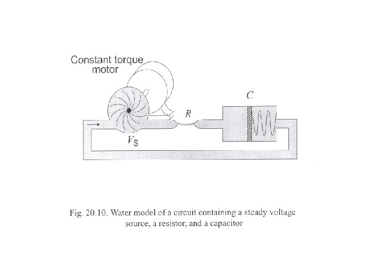
We compute with pulses voltage RC Circuits Abound in Computers We send beautiful pulses in voltage But we receive lousy-looking pulses at the output time Capacitor charging effects are responsible! Every node in a circuit has natural capacitance, and it is the charging of these capacitances that limits real circuit performance (speed)
RC Circuit Model Every digital circuit has natural resistance and capacitance. In real life, the resistance and capacitance can be estimated using characteristics of the materials used and the layout of the physical device. R Vout The value of R and C + + for a digital circuit Vout Vin C _ determine how long it will _ take the capacitor to change its voltage—the gate delay.
RC Circuit Model With the digital context in mind, Vin will usually be a time-varying voltage that Vin switches instantaneously between logic 1 voltage and logic 0 voltage. R Vout + C Vout _ + _ t=0 We often represent this switching voltage with a switch in the circuit diagram. i + V =5 V s + Vout –
Analysis of RC Circuit R • By KVL, Vin + _ Vout I + C Vout _ • Using the capacitor I-V relationship, • We have a first-order linear differential equation for the output voltage
Analysis of RC Circuit R • What does that mean? Vin • One could solve the differential equation to get + _ Vout I + C Vout _
Insight • Vout(t) starts at Vout(0) and goes to Vin asymptotically. • The difference between the two values decays exponentially. • The rate of convergence depends on RC. The bigger RC is, the slower the convergence. Vout(0) Vout Vin bigger RC Vout(0) Vin 0 0 0 time
Time Constant • The value RC is called the time constant. • After 1 time constant has passed (t = RC), the above works out to: • So after 1 time constant, Vout(t) has completed 63% of its transition, with 37% left to go. • After 2 time constants, only 0. 372 left to go. Vout Vin Vout(0) . 63 V 1. 37 Vout(0) 0 0 t time
Transient vs. Steady-State R Vin + _ Vout I + C Vout _ • When Vin does not match up with Vout , due to an abrupt change in Vin for example, Vout will begin its transient period where it exponentially decays to the value of Vin. • After a while, Vout will be close to Vin and be nearly constant. We call this steady-state. • In steady state, the current through the capacitor is (approx) zero. The capacitor behaves like an open circuit in steady-state. • Why? I = C d. Vout/dt, and Vout is constant in steady-state.
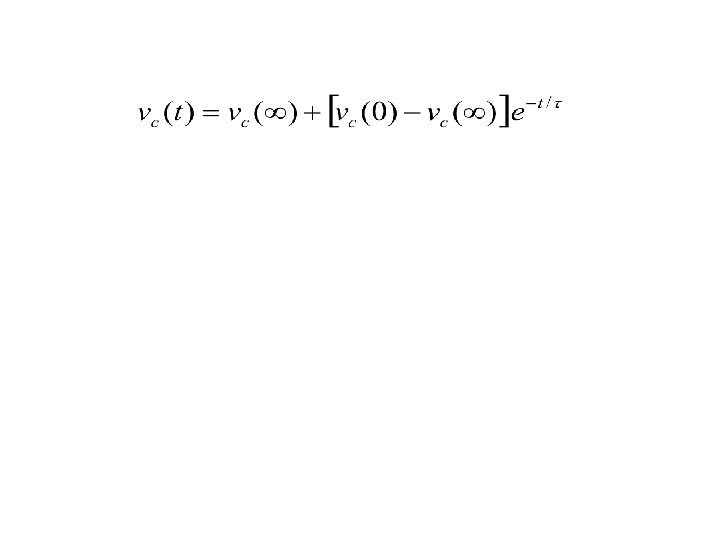
General RC Solution • Every current or voltage (except the source voltage) in an RC circuit has the following form: • x represents any current or voltage • t 0 is the time when the source voltage switches • xf is the final (asymptotic) value of the current or voltage All we need to do is find these values and plug in to solve for any current or voltage in an RC circuit.
Solving the RC Circuit We need the following three ingredients to fill in our equation for any current or voltage: • x(t 0+) This is the current or voltage of interest just after the voltage source switches. It is the starting point of our transition, the initial value. • xf This is the value that the current or voltage approaches as t goes to infinity. It is called the final value. • RC This is the time constant. It determines how fast the current or voltage transitions between initial and final value.
Finding the Initial Condition To find x(t 0+), the current or voltage just after the switch, we use the following essential fact: Capacitor voltage is continuous; it cannot jump when a switch occurs. So we can find the capacitor voltage VC(t 0+) by finding VC(t 0 -), the voltage before switching. We can assume the capacitor was in steady-state before switching. The capacitor acts like an open circuit in this case, and it’s not too hard to find the voltage over this open circuit. We can then find x(t 0+) using VC(t 0+) using KVL or the capacitor I-V relationship. These laws hold for every instant in time.
Finding the Final Value To find xf , the asymptotic final value, we assume that the circuit will be in steady-state as t goes to infinity. So we assume that the capacitor is acting like an open circuit. We then find the value of current or voltage we are looking for using this open-circuit assumption. Here, we use the circuit after switching along with the open-circuit assumption. When we found the initial value, we applied the open-circuit assumption to the circuit before switching, and found the capacitor voltage which would be preserved through the switch.
Finding the Time Constant It seems easy to find the time constant: it equals RC. But what if there is more than one resistor or capacitor? R is the Thevenin equivalent resistance with respect to the capacitor terminals. Remove the capacitor and find RTH. It might help to turn off the voltage source. Use the circuit after switching.
Natural Response Summary RL Circuit RC Circuit i L + R C v R – • Inductor current cannot change instantaneously • Capacitor voltage cannot change instantaneously • time constant • time constant
RC Circuit Transient Analysis Example The switch is closed for t < 0, and then opened at t = 0. Find the voltage vc(t) for t ≥ 0. t=0 3 k. W i 5 V + + vc 10 m. F – 1. Determine the initial voltage vc(0) 2 k. W
3 k. W i 5 V + + vc – 2. Determine the final voltage vc(∞) 3. Calculate the time constant t 10 m. F 2 k. W