
Transformer Voltage Regulation PRESENTED BY PROF VG PATEL

Transformer Voltage Regulation PRESENTED BY PROF. VG PATEL
TRANSFORMER ENCYCLOPAEDIA VOLTAGE REGULATION TRANSFORMER REGULATION (TRANSFORMER VOLTAGE REGULATION) What is voltage regulation? The voltage regulation of the transformer is the relationship of the no load condition (open circuit) to the (full load condition). Tuesday, June 8, 2021 PROF. V. G. PATEL 2
TRANSFORMER ENCYCLOPAEDIA VOLTAGE REGULATION “Full-load” means the point at which the transformer is operating at maximum permissible secondary current. This operating point will be determined primarily by the winding wire size (ampacity) and the method of transformer cooling. Transformer regulation is a measure of the voltage rise on the secondary due to off-load or light-load conditions with the primary input voltage remaining constant i. e. the measure of how well a power transformer maintains constant secondary voltage over a range of load currents is called the transformer's voltage regulation. It can be calculated from the following formula: This measure is expressed as a percentage of the secondary voltage. Tuesday, June 8, 2021 PROF. V. G. PATEL 3
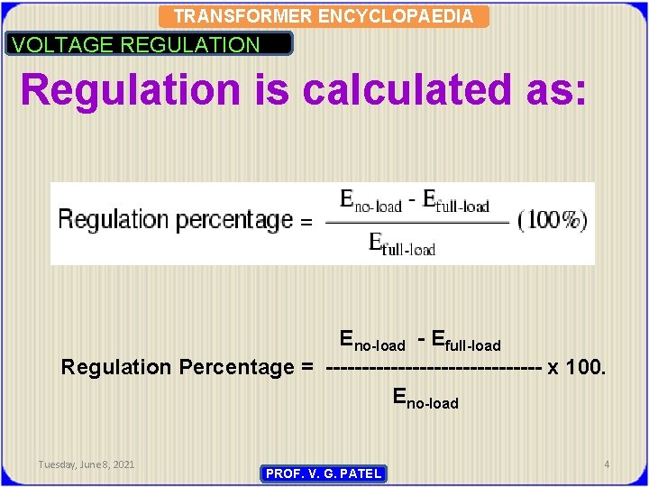
TRANSFORMER ENCYCLOPAEDIA VOLTAGE REGULATION Regulation is calculated as: Eno-load - Efull-load Regulation Percentage = --------------- x 100. Eno-load Tuesday, June 8, 2021 PROF. V. G. PATEL 4
TRANSFORMER ENCYCLOPAEDIA VOLTAGE REGULATION Since, it is expressed as a percentage of the secondary voltage, some author takes no-load voltage as reference voltage and some author takes full-load voltage as reference voltage. Secondary full-load voltage depends upon the load Power Factor and hence, not constant. Whereas secondary no-load voltage is constant and in most of the cases, it is taken as reference voltage (i. e. in the denominator of the formula). {as V 2 no-load ~V 2 rated}. Tuesday, June 8, 2021 PROF. V. G. PATEL 5
TRANSFORMER ENCYCLOPAEDIA VOLTAGE REGULATION What voltage regulation means in the real world? Many people mistake this to mean that a transformer with 10% regulation will keep the output voltage to a value within 10% of nominal. That's simply not so. Let's take a look at what transformer voltage regulation is, and why it's useful. In any transformer, the secondary current produces voltage drop across the resistive and reactive components of the transformer's secondary side. On the other side, the primary current produces voltage drops across the resistive and reactive components of the transformer's primary side. From this, it's easy to see the primary voltage will be less than the supply voltage, and the secondary (output) will be less than either of those (for step down trans. ). Tuesday, June 8, 2021 PROF. V. G. PATEL 6
TRANSFORMER ENCYCLOPAEDIA VOLTAGE REGULATION Let's assume no load is connected to transformer. In such a case, no secondary current flows. With no current, no voltage drop across those resistive and reactive components of the transformer's secondary side. But, another thing happens. Without a secondary current, the primary current drops to the no-load current - which is nearly zero. This means the voltage drop across the resistive and reactive components of the transformer's primary side becomes very small. What's the net effect? In a noload situation, the voltage on the primary is almost equal to the supply voltage, and the secondary voltage nearly equals the supply voltage times the ratio of primary windings to secondary windings. 7 Tuesday, June 8, 2021 PROF. V. G. PATEL
TRANSFORMER ENCYCLOPAEDIA VOLTAGE REGULATION One might assume the transformer's output voltage is highest at no load. It would then make sense that (under loaded conditions) the transformer's resistive and reactive components cause the output voltage to drop below its no-load level. This is a logical assumption, but not necessarily so. Depending on the power factor of the load, the output full-load voltage may actually be larger than the no-load voltage. Tuesday, June 8, 2021 PROF. V. G. PATEL 8
TRANSFORMER ENCYCLOPAEDIA VOLTAGE REGULATION The voltage regulation of the transformer is the percentage change in the output voltage from no-load to full-load. And since power factor is a determining factor in the secondary voltage, power factor influences voltage regulation. This means the voltage regulation of a transformer is a dynamic, loaddependent number. The numbers you see in the nameplate data are fixed; the number of primary windings won't change; the number of secondary windings also won't change, etc. But, the voltage regulation will vary as power factor varies. Tuesday, June 8, 2021 PROF. V. G. PATEL 9
TRANSFORMER ENCYCLOPAEDIA VOLTAGE REGULATION Ideally, there should be no change in the transformer's output voltage from no-load to full-load. In such a case, we say the voltage regulation is 0 %. To get the best performance out of transformer, one need the lowest possible voltage regulation. One should calculate the voltage regulation and save the result as a troubleshooting and predictive maintenance benchmark. Suppose the percentage change is too high, what one should do? One now know, one need to look at power factor correction for the loads on that transformer. Tuesday, June 8, 2021 PROF. V. G. PATEL 10
TRANSFORMER ENCYCLOPAEDIA VOLTAGE REGULATION There are some applications, however, where poor regulation is actually desired. One such case is in discharge lighting, where a step-up transformer is required to initially generate a high voltage (necessary to “ignite” the lamps), then the voltage is expected to drop off once the lamp begins to draw current. This is because discharge lamps' voltage requirements tend to be much lower after a current has been established through the arc path. In this case, a step-up transformer with poor voltage regulation suffices nicely for the task of conditioning power to the lamp. Tuesday, June 8, 2021 PROF. V. G. PATEL 11
TRANSFORMER ENCYCLOPAEDIA VOLTAGE REGULATION Another application is in current control for AC arc welders, which are nothing more than step-down transformers supplying low-voltage, high-current power for the welding process. A high voltage is desired to assist in “striking” the arc (getting it started), but like the discharge lamp, an arc doesn't require as much voltage to sustain itself once the air has been heated to the point of ionization. Thus, a decrease of secondary voltage under high load current would be a good thing. Some arc welder designs provide arc current adjustment by means of a movable iron core in the transformer, cranked in or out of the winding assembly by the operator. Moving the iron slug away from the windings reduces the strength of magnetic coupling between the windings, which diminishes no-load secondary voltage and makes for poorer voltage regulation. Tuesday, June 8, 2021 PROF. V. G. PATEL 12
TRANSFORMER ENCYCLOPAEDIA VOLTAGE REGULATION SIGNIFICANCE OF VOLTAGE REGULATION v. With the rated voltage applied to the primary winding, the terminal voltage varies with the load current and load power factor. v. This variation is called voltage regulation. v. Voltage regulation occurs mainly due to the voltage drop in the impedance of the transformer, load current and load P. F. v. For lagging P. F. of load, the secondary voltage is reduced on load current. v. For leading P. F. of load, the secondary voltage increases slightly with load current. Tuesday, June 8, 2021 PROF. V. G. PATEL 13
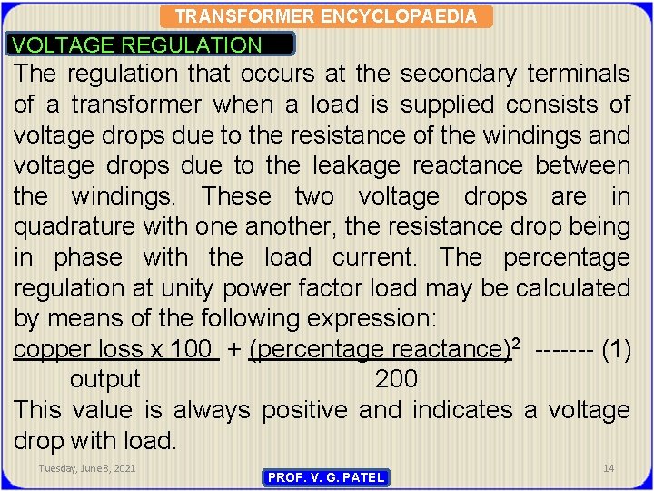
TRANSFORMER ENCYCLOPAEDIA VOLTAGE REGULATION The regulation that occurs at the secondary terminals of a transformer when a load is supplied consists of voltage drops due to the resistance of the windings and voltage drops due to the leakage reactance between the windings. These two voltage drops are in quadrature with one another, the resistance drop being in phase with the load current. The percentage regulation at unity power factor load may be calculated by means of the following expression: copper loss x 100 + (percentage reactance)2 ------- (1) output 200 This value is always positive and indicates a voltage drop with load. Tuesday, June 8, 2021 PROF. V. G. PATEL 14
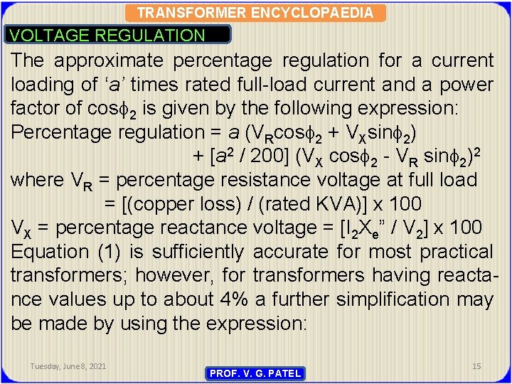
TRANSFORMER ENCYCLOPAEDIA VOLTAGE REGULATION The approximate percentage regulation for a current loading of ‘a’ times rated full-load current and a power factor of cos 2 is given by the following expression: Percentage regulation = a (VRcos 2 + VXsin 2) + [a 2 / 200] (VX cos 2 - VR sin 2)2 where VR = percentage resistance voltage at full load = [(copper loss) / (rated KVA)] x 100 VX = percentage reactance voltage = [I 2 Xe” / V 2] x 100 Equation (1) is sufficiently accurate for most practical transformers; however, for transformers having reactance values up to about 4% a further simplification may be made by using the expression: Tuesday, June 8, 2021 PROF. V. G. PATEL 15
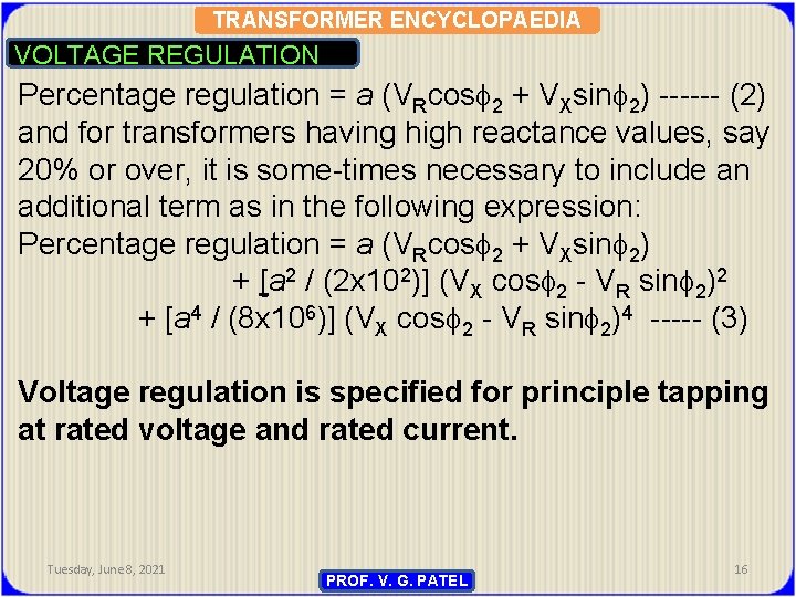
TRANSFORMER ENCYCLOPAEDIA VOLTAGE REGULATION Percentage regulation = a (VRcos 2 + VXsin 2) ------ (2) and for transformers having high reactance values, say 20% or over, it is some-times necessary to include an additional term as in the following expression: Percentage regulation = a (VRcos 2 + VXsin 2) + [a 2 / (2 x 10²)] (VX cos 2 - VR sin 2)2 + [a 4 / (8 x 10⁶)] (VX cos 2 - VR sin 2)4 ----- (3) Voltage regulation is specified for principle tapping at rated voltage and rated current. Tuesday, June 8, 2021 PROF. V. G. PATEL 16
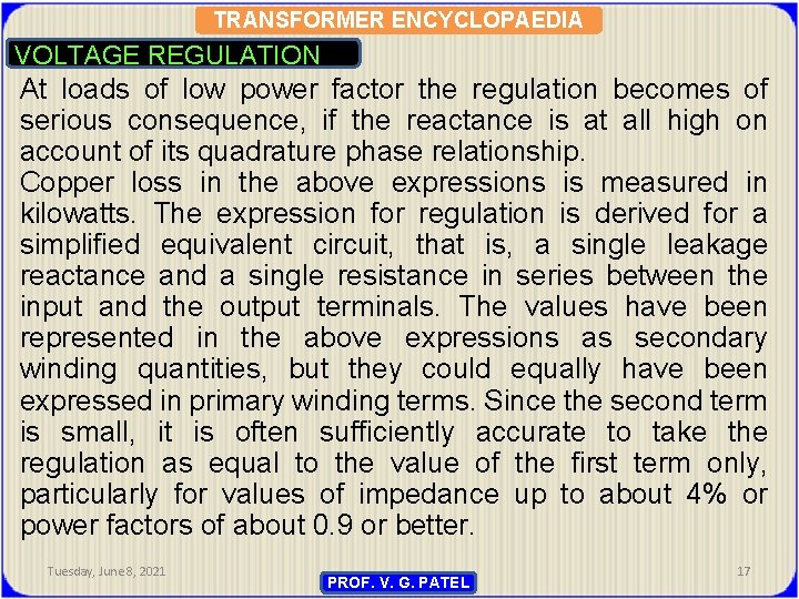
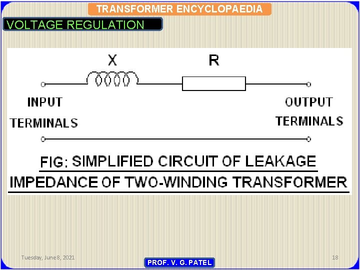
TRANSFORMER ENCYCLOPAEDIA VOLTAGE REGULATION At loads of low power factor the regulation becomes of serious consequence, if the reactance is at all high on account of its quadrature phase relationship. Copper loss in the above expressions is measured in kilowatts. The expression for regulation is derived for a simplified equivalent circuit, that is, a single leakage reactance and a single resistance in series between the input and the output terminals. The values have been represented in the above expressions as secondary winding quantities, but they could equally have been expressed in primary winding terms. Since the second term is small, it is often sufficiently accurate to take the regulation as equal to the value of the first term only, particularly for values of impedance up to about 4% or power factors of about 0. 9 or better. Tuesday, June 8, 2021 PROF. V. G. PATEL 17
TRANSFORMER ENCYCLOPAEDIA VOLTAGE REGULATION Tuesday, June 8, 2021 PROF. V. G. PATEL 18
TRANSFORMER ENCYCLOPAEDIA VOLTAGE REGULATION VX may be obtained theoretically by calculation or actually from the tested impedance and losses of the transformer. It should be noted that the per cent resistance used is that value obtained from the transformer losses, since this takes into account eddycurrent losses and stray losses within the transformer. This is sometimes termed the AC resistance, as distinct from the value which would be measured by passing direct current through the windings and measuring the voltage drop. Tuesday, June 8, 2021 PROF. V. G. PATEL 19
TRANSFORMER ENCYCLOPAEDIA VOLTAGE REGULATION It will be seen from equations that the final regulation formula is the same for lagging and leading power factors provided the angle is the true angle of lag measured clockwise from the position of the secondary terminal voltage phasor. Thus, in the case of a lagging power factor cos the angle is substituted directly into the regulation formula, but in the case of a leading power factor cos the angle to be substituted is not but -. If the percentage regulation comes out negative, it indicates that the load has produced a rise in voltage. Tuesday, June 8, 2021 PROF. V. G. PATEL 20
TRANSFORMER ENCYCLOPAEDIA VOLTAGE REGULATION When the transformer is loaded, with a constant primary voltage, then the secondary terminal voltage drops (assuming lagging power-factor); it will increase, if power factor is leading, because of its internal resistance and leakage reactance. Let V 2 = secondary terminal voltage at no-load V`2= secondary terminal voltage at load % Regulation = [(V 2 –V`2) / V 2] x 100 Then, % regulation of a loaded transformer at any power factor is given as (Xcos + Rsin ) + [(Xcos - Rsin )2] / 200 where R = percentage resistive drop X = percentage reactive drop cos = lagging power-factor. Tuesday, June 8, 2021 PROF. V. G. PATEL 21
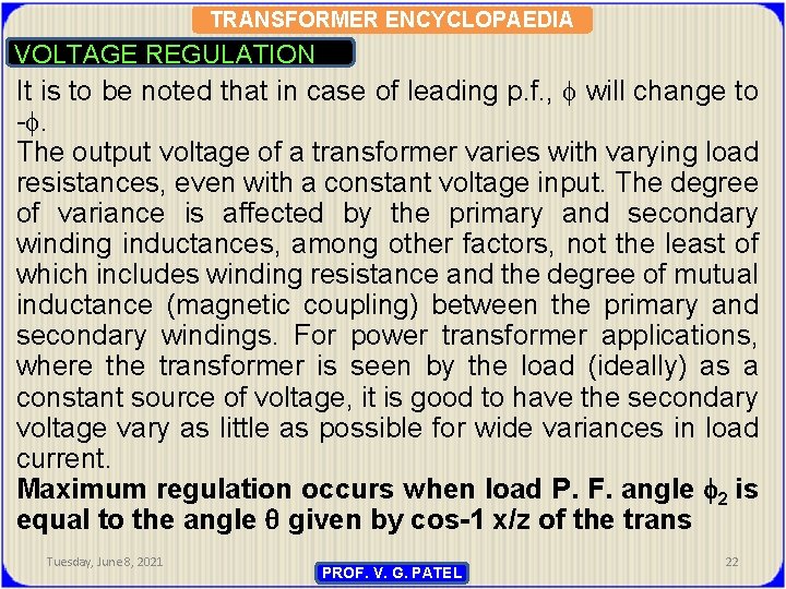
TRANSFORMER ENCYCLOPAEDIA VOLTAGE REGULATION It is to be noted that in case of leading p. f. , will change to -. The output voltage of a transformer varies with varying load resistances, even with a constant voltage input. The degree of variance is affected by the primary and secondary winding inductances, among other factors, not the least of which includes winding resistance and the degree of mutual inductance (magnetic coupling) between the primary and secondary windings. For power transformer applications, where the transformer is seen by the load (ideally) as a constant source of voltage, it is good to have the secondary voltage vary as little as possible for wide variances in load current. Maximum regulation occurs when load P. F. angle 2 is equal to the angle given by cos-1 x/z of the trans Tuesday, June 8, 2021 PROF. V. G. PATEL 22
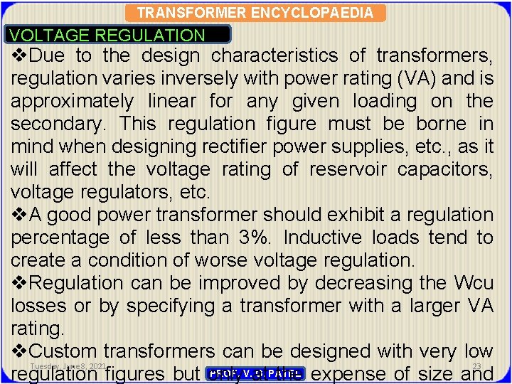
TRANSFORMER ENCYCLOPAEDIA VOLTAGE REGULATION v. Due to the design characteristics of transformers, regulation varies inversely with power rating (VA) and is approximately linear for any given loading on the secondary. This regulation figure must be borne in mind when designing rectifier power supplies, etc. , as it will affect the voltage rating of reservoir capacitors, voltage regulators, etc. v. A good power transformer should exhibit a regulation percentage of less than 3%. Inductive loads tend to create a condition of worse voltage regulation. v. Regulation can be improved by decreasing the Wcu losses or by specifying a transformer with a larger VA rating. v. Custom transformers can be designed with very low Tuesday, June 8, 2021 23 PROF. V. G. PATEL regulation figures but only at the expense of size and
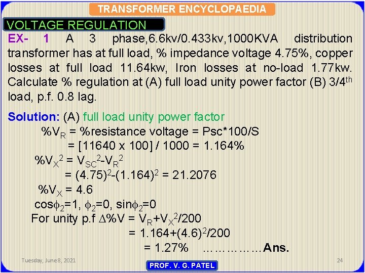
TRANSFORMER ENCYCLOPAEDIA VOLTAGE REGULATION EX- 1 A 3 phase, 6. 6 kv/0. 433 kv, 1000 KVA distribution transformer has at full load, % impedance voltage 4. 75%, copper losses at full load 11. 64 kw, Iron losses at no-load 1. 77 kw. Calculate % regulation at (A) full load unity power factor (B) 3/4 th load, p. f. 0. 8 lag. Solution: (A) full load unity power factor %VR = %resistance voltage = Psc*100/S = [11640 x 100] / 1000 = 1. 164% %VX 2 = VSC 2 -VR 2 = (4. 75)2 -(1. 164)2 = 21. 2076 %VX = 4. 6 cos 2=1, 2=0, sin 2=0 For unity p. f %V = VR+VX 2/200 = 1. 164+(4. 6) 2/200 = 1. 27% ……………Ans. Tuesday, June 8, 2021 PROF. V. G. PATEL 24

TRANSFORMER ENCYCLOPAEDIA VOLTAGE REGULATION (B) At 3/4 th load, p. f 0. 8 lag. cos 2 = 0. 8, sin 2 = 0. 6 %regulation at 3/4 th load and p. f 0. 8 lag VR = %resistance voltage at 3/4 th load =1. 164 x 0. 75 = 0. 874% VX = %reactance voltage at 3/4 th load = 4. 6 x 0. 75 = 3. 45% % V = (VR cos 2 + VXsin 2) + (VX cos 2 – VRsin 2)2/200 = (0. 874*0. 8)+(3. 45*0. 6) + [(3. 45*0. 8)-(0. 874*0. 6)]2/200 = 0. 6992 + 2. 07 + (2. 76 – 0. 5244)2 / 200 = 0. 6992 + 2. 07 + (2. 1356)2 / 200 = 0. 6992 + 2. 07 + 0. 0228 = 2. 792 = 2. 8%-------Ans. Tuesday, June 8, 2021 PROF. V. G. PATEL 25
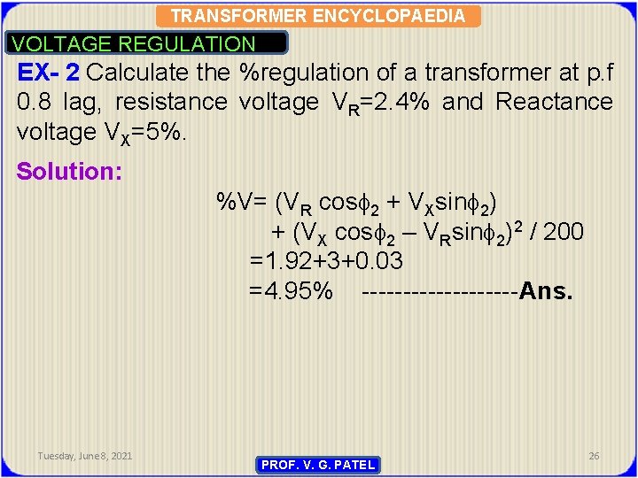
TRANSFORMER ENCYCLOPAEDIA VOLTAGE REGULATION EX- 2 Calculate the %regulation of a transformer at p. f 0. 8 lag, resistance voltage VR=2. 4% and Reactance voltage VX=5%. Solution: %V= (VR cos 2 + VXsin 2) + (VX cos 2 – VRsin 2)2 / 200 =1. 92+3+0. 03 =4. 95% ----------Ans. Tuesday, June 8, 2021 PROF. V. G. PATEL 26
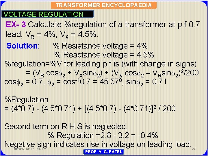
TRANSFORMER ENCYCLOPAEDIA VOLTAGE REGULATION EX- 3 Calculate %regulation of a transformer at p. f 0. 7 lead, VR = 4%, VX = 4. 5%. Solution: % Resistance voltage = 4% % Reactance voltage = 4. 5% %regulation=%V for leading p. f is (with change in signs) = (VR cos 2 + VXsin 2) + (VX cos 2 – VRsin 2)2/200 cos 2 = 0. 7, 2 = cos-10. 7 = 45. 570, sin 2 = 0. 71 %Regulation = (4*0. 7) - (4. 5*0. 71) + [(4. 5*0. 7) - (4*0. 71)]2 / 200 Second term on R. H. S is neglected, % Regulation =2. 8 - 3. 2 = -0. 4% Negative sign indicates rise in voltage on leading load. 27 Tuesday, June 8, 2021 PROF. V. G. PATEL
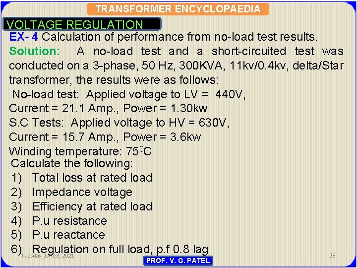
TRANSFORMER ENCYCLOPAEDIA VOLTAGE REGULATION EX- 4 Calculation of performance from no-load test results. Solution: A no-load test and a short-circuited test was conducted on a 3 -phase, 50 Hz, 300 KVA, 11 kv/0. 4 kv, delta/Star transformer, the results were as follows: No-load test: Applied voltage to LV = 440 V, Current = 21. 1 Amp. , Power = 1. 30 kw S. C Tests: Applied voltage to HV = 630 V, Current = 15. 7 Amp. , Power = 3. 6 kw Winding temperature: 750 C Calculate the following: 1) Total loss at rated load 2) Impedance voltage 3) Efficiency at rated load 4) P. u resistance 5) P. u reactance 6)Tuesday, Regulation on full load, p. f 0. 8 lag June 8, 2021 28 PROF. V. G. PATEL
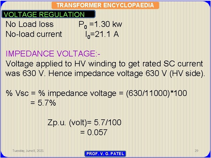
TRANSFORMER ENCYCLOPAEDIA VOLTAGE REGULATION No Load loss No-load current P 0 =1. 30 kw I 0=21. 1 A IMPEDANCE VOLTAGE: Voltage applied to HV winding to get rated SC current was 630 V. Hence impedance voltage 630 V (HV side). % Vsc = % impedance voltage = (630/11000)*100 = 5. 7% Zp. u. (volt)= 5. 7/100 = 0. 057 Tuesday, June 8, 2021 PROF. V. G. PATEL 29

TRANSFORMER ENCYCLOPAEDIA VOLTAGE REGULATION %VR = % Resistance voltage = (PSC /S) *100 = (3. 08/300) *100 = 1. 02% p. u. resistance voltage = %resistance voltage / 100 = 1. 02 / 100 = 0. 01 p. u. reactance voltage = [Vsc 2 - VR 2]1/2 = [(0. 057)2 - (0. 01)2]1/2 = 0. 057 p. u. Regulation: %V = VR cos 2 + VXsin 2 = (1. 02*0. 8)+(5. 7*0. 6) = (0. 816+3. 42) = 4. 236% ……………. . Ans. Tuesday, June 8, 2021 PROF. V. G. PATEL 30
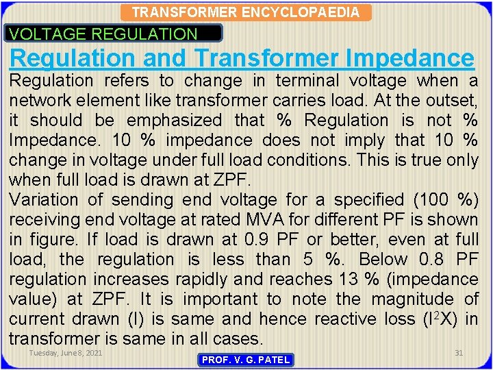
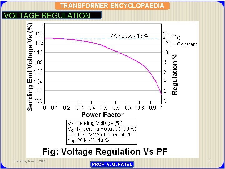
TRANSFORMER ENCYCLOPAEDIA VOLTAGE REGULATION Regulation and Transformer Impedance Regulation refers to change in terminal voltage when a network element like transformer carries load. At the outset, it should be emphasized that % Regulation is not % Impedance. 10 % impedance does not imply that 10 % change in voltage under full load conditions. This is true only when full load is drawn at ZPF. Variation of sending end voltage for a specified (100 %) receiving end voltage at rated MVA for different PF is shown in figure. If load is drawn at 0. 9 PF or better, even at full load, the regulation is less than 5 %. Below 0. 8 PF regulation increases rapidly and reaches 13 % (impedance value) at ZPF. It is important to note the magnitude of current drawn (I) is same and hence reactive loss (I 2 X) in transformer is same in all cases. Tuesday, June 8, 2021 PROF. V. G. PATEL 31
TRANSFORMER ENCYCLOPAEDIA VOLTAGE REGULATION Even though HV to MV impedances are above 22 %, the regulation is only 8 %, since the load PF is not low (0. 8). In case of large power transformer (600 MVA and above), impedances in the range of 15 % to 25 % are common. These large values are chosen to limit the fault level within available breaker capacity. But large impedance values do not cause regulation problem as long as the load is at good PF. At EHV level, the load flow PF is generally above o. 95. Tuesday, June 8, 2021 PROF. V. G. PATEL 32
TRANSFORMER ENCYCLOPAEDIA VOLTAGE REGULATION Tuesday, June 8, 2021 PROF. V. G. PATEL 33
TRANSFORMER ENCYCLOPAEDIA VOLTAGE REGULATION Summary: - A transformer has inherent impedance (Ze). The impedance has two components called resistance R and leakage reactance X. Leakage reactance predominates. Leakage reactance is caused by leakage flux which does not flow through the core and does not link with both primary and secondary. For measurement and calculation purpose the impedance is specified in terms of impedance voltage. Impedance voltage is further divided into two components. --Resistance voltage VR --Reactance voltage VX VZ 2 = VR 2+VX 2 Impedance Voltage (Vz) is determined by conducting shortcircuit voltage and is called short-circuit voltage (Vsc) Vz = Vsc Tuesday, June 8, 2021 PROF. V. G. PATEL 34
TRANSFORMER ENCYCLOPAEDIA VOLTAGE REGULATION CONCLUSION Voltage regulation is the measure of how well a power transformer can maintain constant secondary voltage at given a constant primary voltage and wide variance in load current. The lower the percentage (closer to zero), the more stable the secondary voltage and the better the regulation it will provide. Tuesday, June 8, 2021 PROF. V. G. PATEL 35

TRANSFORMER ENCYCLOPAEDIA OPEN FORUM Tuesday, June 8, 2021 36

TRANSFORMER ENCYCLOPAEDIA THANQ Tuesday, June 8, 2021 37
- Slides: 37