Transformer Transformer What is transformer Types of transformer


- Slides: 41
Transformer
Transformer • What is transformer? • Types of transformer • Need of transformer
Principle of transformer • Electromagnetic induction • Self induction and mutual induction • Teaching aid: Exp. Eyes
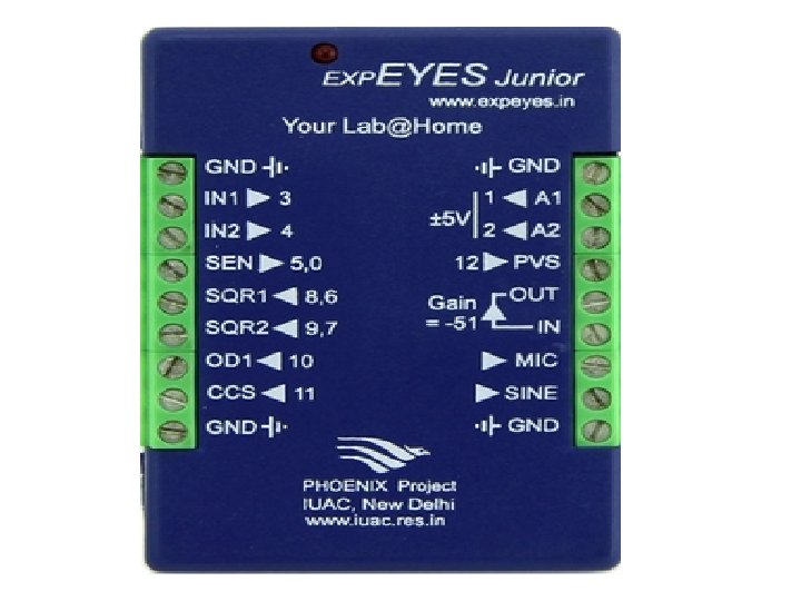
What is Exp. Eyes? • Experiments for Young Engineers and Scientists • PHOENIX (Physics with home made equipment and Innovative Experiments) Project of Inter. University Accelerator Centre (A research centre of UGC)
Electromagnetic induction experiment using Exp. Eyes A 1 Magnet GND
Experiment using Exp. Eyes 1. From EXPERIMENTS open EM Induction 2. Click on Start Scanning. A horizontal trace should appear 3. Drop the magnet through the coil, until a trace is caught. 4. Repeat the process by changing the parameters like magnet strength, speed etc.
Voltage induced on a coil by a moving magnet
Observations • Is the incoming flux equal to the outgoing flux? • Why is the outgoing peak higher than the incoming peak? • Why are the peaks opposite in direction?
Mutual Induction experiment using Exp. Eyes A 2 A 1 SINE 150 Hz , 4 V GND
Mutual induction waveforms on Exp. Eyes
EMF equation of transformer • E 1 = 4. 4. f N 1 Φm V • E 2 = 4. 4. f N 2 Φm V
Ideal transformer vs practical transformer • Copper and eddy current losses • Leakage of flux • Winding resistance • Voltage regulation • Efficiency
Equations related with transformer principle • Ideal characteristics plotted in vaccum or space B μ=B/H H
Transformer losses Copper loss in primary Copper loss in secondary Hysteresis loss Eddy current losses Input power = ep Ip and output power = es Is Output power + losses = Input power
Hysteresis loss •
Hysteresis loss
Eddy current loss • Ampere’s law i Laminations Φ Eddy current loss α B 2 f 2
Voltage second balance • +Bm -Bm
Dot relationship in transformer • Dot polarity indicates phase difference • Dot polarity used to draw a phasor diagram
Transformer parameters 1. Winding resistance 2. Leakage reactance 3. Impedance
Shifting parameters to primary side X 1 R 1 R 2’ =R 2/K 2 X 2’ =R 2/K 2 R 2’ X 2
No load Vector Diagram of Practical transformer E 1 E 2 =V 2
Transformer no load and on load I 2
Phasor diagram without considering winding resistance and magnetic leakage Case 1 : Load is resistive I 1 I 2’ Φ 1 Io I 2 Φ 2=0 E 1= E 2= V 2 Φ
Phasor diagram without considering winding resistance and magnetic leakage Case 1 : Load is inductive I 1 I 2’ Φ 1 Io I 2 Φ 2 E 1= E 2= V 2 Φ
Phasor diagram without considering winding resistance and magnetic leakage Case 1 : Load is capacitive I 1 Φ 1 I 2’ Io Φ Φ 2 I 2 E 1= E 2= V 2
Considering winding resistance and magnetic leakage Write equations related with the above diagram. These equations required to draw phasor diagram.
Considering winding parameters and load is resistive I 1 JX 1 I 1 R 1 I 2’ I 2 R 2 V 2 I 2 X 2 I 1
Considering winding parameters and load is inductive I 1 JX 1 I 1 R 1 I 2’ I 2 V 2 I 2 R 2 I 2 X 2 I 1
Considering winding parameters and load is capacitive I 1 JX 1 I 1 R 1 I 2’ V 2 I 2 R 2 I 2 X 2 I 1
Equivalent circuit of transformer Write the current notations.
Exact equivalent circuit of a transformer referred to the primary
Approximate equivalent circuit R 01 = R 1 + R 2’= equivalent resistance of transformer as referred to primary X 01 = X 1 + X 2’= equivalent reactance of transformer as referred to primary R 0 = equivalent core loss resistance X 0 = magnetizing reactance
Transformer test • Open circuit test • Short circuit test
Open circuit test Low High
Short circuit test
Voltage regulation Ro 1 X 01 C E 2 O I 2 V 2 A I 2 Ro 2 D B I 2 X 02 M N L
Rating of transformer • Meaning of rating • Why transformer rating is in KVA ?
No load Vector Diagram of Practical transformer I 2
Transformer vector diagram under load conditions I 1 R 1 I 1’ I 2 V 2 i 2 R 2 i 2 X 2