TRANSDUCER AND SIGNAL CONDITIONING TSC CHAPTER 1 BASIC
")
TRANSDUCER AND SIGNAL CONDITIONING (TSC)

CHAPTER -1 BASIC CONCEPTS

DEFINITION OF TRANSDUCERS TRANSDUCER IS A DEVICE THAT CONVERTS ONE FORM OF ENERGY INTO ANOTHER USABLE FORM OF ENERGY. EXAMPLE : LVDT, RTD etc.

CLASSIFICATION OF TRANSDUCERS ACTIVE TRANSDUCERS : Active transducers are those which do not require any power source for their operation. They work on the energy conversion principle. They produce an electrical signal proportional to the input (physical quantity). For example, a thermocouple is an active transducer.

PASSIVE TRANSDUCER : Transducers which require an external power source for their operation are called passive transducers. They produce an output signal in the form of some variation in resistance, capacitance or any other electrical parameter, which than has to be converted to an equivalent current or voltage signal. For example RTD, Strain gauges etc.

ANALOG TRANSDUCERS : Analog transducers converts input signal into output signal, which is a continuous function of time such as THERMISTOR , strain gauge, LVDT , thermocouple etc. DIGITAL TRANSDUCERS : Digital transducers converts input signal into the output signal in the form of pulses , such as Shaft Encoders.

INVERSE TRANSDUCERS : Inverse transducer is defined as a device which converts an electrical quantity into a non electrical quantity: A piezoelectric crystal acts as inverse transducer because when a voltage is applied across its surfaces, it changes its dimensions causing a mechanical displacement.

SELECTION CRITERIA OF TRANSDUCERS Operating Principle : The transducers are selected on the basis of operating principle it may be resistive, inductive, capacitive, optical etc. Operating range : The range of transducer should be appropriate for measurement to get a good resolution. Accuracy : The accuracy should be as high as possible or as per the measurement.

Range : The transducer can give good result within its specified range, so select transducer as per the operating range. Sensitivity : The transducer should be more sensitive to produce the output or sensitivity should be as per requirement. Loading effect : The transducer’s input impedance should be high and output impedance should be low to avoid loading effect. Errors : The error produced by the transducer should be low as possible.

Environmental compatibility : The transducer should maintain input and output characteristic for the selected environmental condition.

TRANSDUCERS CHARACTERISTICS Accuracy Precision Resolution Sensitivity Drift

Linearity Span Hysteresis Distortion Noise

CHAPTER -2 VARIABLE RESISTANCE TRANSDUCER

POTENTIOMETER A variable resistor with a third adjustable terminal. The potential at the third terminal can be adjusted to give any fraction of the potential across the ends of the resistor.

PRINCIPLE OF POTENIOMETER The principle of the potentiometer is that: For a wire having uniform area of cross section and uniform composition , the potential drop is directly proportional to the length of wire.

DIAGRAM OF POTENTIOMETER

SYMBOL OF POTENTIOMETER

WORKING OF POTENTIOMETER A potentiometer has three terminals. When connected to a circuit, the two fixed terminals are connected to the ends of the resistive elements while third terminal is connected to the wiper. In the circuit diagram shown above, the terminals of the potentiometer are marked 1, 2 and 3. The voltage supply is connected across terminals 1 and 3, positive lead to terminal one while negative lead to terminal three. The terminal 2 is connected to the wiper.

We can see that at the current position of wiper, there are two resistive paths just like the resistor is split into two resistors. Out of these two resistors, the one having longer resistive path will have a higher resistance. This is due to the fact that resistance of a resistor depends on its length (since R=ρ). Higher the length, higher is the resistance, provided the material of the resistor and its crosssectional area remains same.
} x V ; where V= supply voltage.")
Vout = {R 2/(R 1+R 2)} x V ; where V= supply voltage.
 is a")
STRAIN GAUGE A Strain gauge (sometimes referred to as a Strain gage) is a sensor whose resistance varies with applied force; It converts force, pressure, tension, weight, etc. , into a change in electrical resistance which can then be measured.

PRINCIPLE OF STRAIN GAUGE A strain gauge is a device used to measure strain on an object. As the object is deformed, the foil is deformed, causing its electrical resistance to change. This resistance change, usually measured using a Wheatstone bridge, is related to the strain by the quantity known as the gauge factor.

STRAIN GAUGE DIAGRAM

WORKING OF STRAIN GAUGE A strain gauge is a device used to measure strain on an object. The most common type of strain gauge consists of an insulating flexible backing which supports a metallic foil pattern. The gauge is attached to the object by a suitable adhesive. As the object is deformed, the foil is deformed, causing its electrical resistance to change. This resistance change, usually measured using a Wheatstone bridge, is related to the strain by the quantity known as the gauge factor.
 or strain factor of a strain gauge is")
GAUGE FACTOR : Gauge factor (GF) or strain factor of a strain gauge is the ratio of relative change in electrical resistance R, to the mechanical strain ε.
 also called")
LVDT : LINEAR VARIABLE DIFFERNTIAL TRANSFORMER The linear variable differential transformer (LVDT) also called linear variable displacement transformer, linear variable displacement transducer, or simply differential transformer) is a type of electrical transformer used for measuring linear displacement (position).

LVDT PRINCIPLE LVDT works under the principle of mutual induction, and the displacement which is a nonelectrical energy is converted into an electrical energy.

LVDT DIAGRAM

WORKING OF LVDT Case 1: On applying an external force which is the displacement, if the core reminds in the null position itself without providing any movement then the voltage induced in both the secondary windings are equal which results in net output is equal to zero i. e. , Esec 1 -Esec 2=0 Case 2: When an external force is applied and if the steel iron core tends to move in the left hand side direction the emf voltage induced in the secondary coil is greater when compared to the emf induced in the secondary coil 2. Therefore the net output will be Esec 1 -Esec 2

Case 3: When an external force is applied and if the steel iron core moves in the right hand side direction the emf induced in the secondary coil 2 is greater when compared to the emf voltage induced in the secondary coil 1. therefore the net output voltage will be Esec 2 -Esec 1
 is a device with")
RTD : RESISTANCE TEMPERATURE DETECTOR A Resistance Temperature Detector (RTD) is a device with a significant temperature coefficient (that is, its resistance varies with temperature). It is used as a temperature measurement device, usually by passing a low-level current through it and measuring the voltage drop.
 is a temperature sensor that operates")
PRINCIPLE OF RTD An RTD (resistance temperature detector) is a temperature sensor that operates on the measurement principle that a material’s electrical resistance changes with temperature.

RTD DIAGRAM
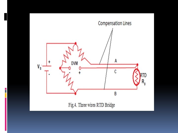

RTD WORKING A Resistance Thermometer or Resistance Temperature Detector is a device which used to determine the temperature by measuring the resistance of pure electrical wire. This wire is referred to as a temperature sensor. If we want to measure temperature with high accuracy, RTD is the only one solution in industries. It has good linear characteristics over a wide range of temperature.

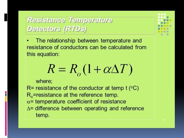
A Resistance Thermometer or Resistance Temperature Detector is a device which used to determine the temperature by measuring the resistance of pure electrical wire. This wire is referred to as a temperature sensor. If we want to measure temperature with high accuracy, RTD is the only one solution in industries. It has good linear characteristics over a wide range of temperature. The variation of resistance of the metal with the variation of the temperature is given as,

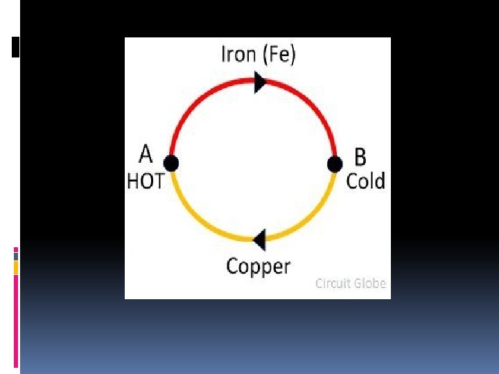
THERMOCOUPLE A thermoelectric device for measuring temperature, consisting of two wires of different metals connected at two points, a voltage being developed between the two junctions in proportion to the temperature difference.

PRINCIPLE & WORKING OF THERMOCOUPLE The working principle of thermocouple depends on the three effects. See back Effect – The See back effect occurs between two different metals. When the heat provides to any one of the metal, the electrons start flowing from hot metal to cold metal. Thus, direct current induces in the circuit.

Peltier Effect – The Peltier effect is the inverse of the Seeback effect. The Peltier effect state that the temperature difference can be created between any two different conductors by applying the potential difference between them. Thompson Effect – The Thompson effect state that when two dissimilar metals join together and if they create two junctions then the voltage induces the entire length of the conductor because of the temperature gradient. The temperature gradient is a physical term which shows the direction and rate of change of temperature at a particular location.
- Slides: 41