Training Course XL 2 800 XL 2 980


- Slides: 153

Training Course XL 2 800 & XL 2 980

Running Order § History of handheld XRF § How it works § Your XL 2 parts and Accessories § XL 2 radiation Safety § Using your XL 2 Analyser § Using your Analyser with your PC § Advanced Settings 2

History of handheld XRF

From Early XRF Testing Tool to Present 5 kg Electronic Unit 1. 5 kg Unit TN 9266 ALLOY ANALYSER 5 kg Probe 2009 8 th Generation 1979 2 nd Generation 4

NITON XRF Analyzer Generations – 2007: 7 th Generation 2000: NITON XL-II 2002: NITON XLi, XLp/t 1994: NITON XL 2007: NITON XL 3 p, XL 3 t 5

Key XL 2 Advantages § Very easy to use – even by non technical personnel § Rugged design for real world industrial applications § Truly nondestructive test § From turn on to trigger pull to results in seconds § Confident analysis with technology from the industry leader 6

XL 2 Specifications § 3 lbs 5. 8 oz (1. 53 kg) § 45 k. V miniaturized x ray tube §Detector: High performance semiconductor detector §Fixed angle, color, touch screen display §USB and Bluetooth™communications 7

How XRF Works

How does XRF work? Each of the elements present in a sample produces a unique set of characteristic x rays that is a "fingerprint" for that specific element. XRF analysers determine the chemistry of a sample by measuring the spectrum of the characteristic x ray emitted by the different elements in the sample when it is illuminated by x rays. These x rays are emitted either from a miniaturized x ray tube, or from a small, sealed capsule of radioactive material. 9

How does XRF work? o A fluorescent x-ray is created when an x-ray of sufficient energy strikes an atom in the sample, dislodging an electron from one of the atom's inner orbital shells. o The atom regains stability, filling the vacancy left in the inner orbital shell with an electron from one of the atom's higher energy orbital shells. o The electron drops to the lower energy state by releasing a fluorescent x-ray, and the energy of this x-ray is equal to the specific difference in energy between two quantum states of the electron. 10

XRF at work Atomic Level Process of Fluorescence Production 11

XRF at work When a sample is measured using XRF, each element present in the sample emits own unique fluorescent x-ray energy spectrum. By simultaneously measuring the fluorescent x-rays emitted by the different elements in the sample, the XL 2 can rapidly determine those elements present in the sample and their relative concentrations - in other words, the elemental chemistry of the sample. 12

Excitation Source Macro Level X Ray Production 13

Technical Illustration of a NITON Analyzer DSP converts analog pulses to digital; sends to CPU. Digitized value represents original energy of characteristic X-Ray. Over measuring time, each element’s energy accumulated into a series of element/energy channels. Spectrum contains qualitative and quantitative information from the sampl 14

Detector Si PIN Detector 15

Possible Elements measured with XRF 16

LOD’s (Limit of Detection) XL 2 Time 60 s per filter Matrix Ti-based Alloys Sb 0. 006 Sn 0. 005 Pd 0. 003 Ag 0. 003 Mo 0. 014 Nb 0. 009 Zr 0. 005 Bi 0. 003 Pb 0. 003 Se 0. 005 W 0. 023 Zn 0. 009 Cu 0. 014 Ni 0. 021 Co 0. 018 Fe 0. 044 Mn 0. 039 Cr 0. 036 V 0. 201 Ti N/A Fe-based Alloys 0. 011 0. 009 0. 003 0. 005 0. 023 0. 014 0. 006 0. 011 0. 010 0. 038 0. 022 0. 023 0. 045 0. 151 N/A 0. 045 0. 010 0. 011 0. 016 17 Cu-based Alloys 0. 017 0. 014 0. 006 0. 008 0. 035 0. 023 0. 010 0. 011 0. 014 0. 010 0. 036 0. 132 N/A 0. 028 0. 012 0. 020 0. 013 0. 027 0. 014

LOD’s (Limit of Detection) XL 2 GOLDD Time 60 s per filter (A/S= Application specific) (N/A=Not Applicable) Matrix Al-based Alloys Ti-based Alloys Fe-based Alloys Sb 30 100 150 Sn 30 60 90 Pd 20 25 30 Ru 20 50 70 Mo N/A A/S Nb N/A 200 240 Zr N/A 50 70 Bi 20 35 50 Pb 20 20 75 Se N/A 20 20 W 50 150 200 Zn 30 40 60 Cu 30 75 110 Ni 50 150 220 Co 50 120 750 Fe 75 300 N/A Mn 100 250 220 Cr 200 500 110 V 500 1300 150 Ti 1000 N/A 250 S N/A 100 P N/A 200 Si 700 750 425 Al N/A 4000 3000 Mg 7500 N/A 18 Cu-based Alloys 175 120 35 100 A/S 320 100 65 50 25 220 300 N/A 110 50 75 75 100 150 275 N/A 200 425 3000 N/A

Your XL 2 parts and accessories

XL 2 Battery and charger Charger base Battery Charger mains Battery case 20

XL 2 Windows, front plate Prolene Windows Holster Front Plate Pelican case 21

XL 2 test stand options Portable Test Stand Mobile Test Stand 22

XL 2 radiation Safety

Radiation Safety Radiation safety Scatter Measurements Radiation safety In Beam Measurements 24

Radiation Safety The Niton Model XL 2 analyser contains an x ray tube which emits radiation only when the user turns the x ray tube on. When the x ray tube is on and the shutter is open, as during a measurement, the analyser emits a directed radiation beam. Reasonable effort should be made to maintain exposures to radiation as far below dose limits as is practical. This is known as the ALARA (As Low as Reasonably Achievable) principle. For any given source of radiation, three factors will help minimize your radiation exposure: Time, Distance, and Shielding. 25

Time The longer you are exposed to a source of radiation the longer the radiation is able to interact in your body and the greater the dose you receive. Dose increases in direct proportion to length of exposure. 26

Distance The closer you are to a source of radiation, the more radiation strikes you. Based on geometry alone, dose increases and decreases with an inverse squared relation to your distance from the source of radiation (additional dose rate reduction comes from air attenuation). For example, the radiation dose one foot from a source is nine times greater than the dose three feet from the source. Remember to keep your hands and all body parts away from the front end of the analyser when the shutter is open to minimize your exposure. 27

Shielding is any material that is placed between you and the radiation source. The more material between you and the source, or the denser the material, the less you will be exposed to that radiation. Supplied or optional test stands are an additional source of shielding for analysis. A backscatter shield accessory is also available and may be appropriate in some applications. 28

Exposures to radiation Human dose to radiation is typically measured in rem, or in one thousandths of a rem, called millirem (mrem), 1 rem = 1000 mrem. Another unit of dose is the Sievert (Sv), 1 Sv = 100 rem. The allowable limit for occupational exposure in the U. S (and many other countries) is 5, 000 mrem/year (50 m. Sv/year) for deep (penetrating) dose and 50, 000 mrem/year (500 m. Sv/year) for shallow (i. e. , skin) dose or dose to extremities. Deep, shallow, and extremity exposure from a properly used Niton XL 2 analyser should be less than 200 mrem per year, (2. 0 m. Sv per year) even if the analyser is used as much as 2, 000 hours per year, with the shutter open continuously. The only anticipated exceptions to the 200 mrem maximum annual dose are: 1) routine and frequent analysis of plastic samples without use of a test stand, backscatter shield, or similar additional protective measures, or 2) improper use where a part of the body is in the primary beam path. 29

Exposures to radiation cont Also, consider the use of protective accessories such as a shielded test stand or backscatter shield (or equivalent) when performing routine and/or frequent analysis of any of the following: • light materials (such as plastic, wood, or similarly low density/low atomic mass samples) • thin samples (such as foils, circuit boards, and wires) • samples that are smaller than the analysis window. 30

Exposures to radiation cont Niton XL 2 GOLDD Radiation Profile In Beam Measurements m. Sv/hr k. V u. A Range Contact Deep Contact Shallow 5 cm Deep 30 cm Deep 8 100 Light 0. 1 9800 0. 02 <0. 01 45 44. 4 Main 390 1300 81 5. 1 In beam dose rates were measured using optically stimulated luminescent (OSL) dosimeters. Reported results are based on measurement results that have been reduced to 2 significant digits by rounding up. For example, a measurement result of 1441 would be reported as 1500. 31

Radiation safety cont When the lights are flashing, the primary beam is on, and radiation is being emitted from the front of the analyser. The primary beam Secondary (Scattered) Beam 32

Using your XL 2 Analyser

Opening your case 34

Inspecting your analyser 35

Inspecting your analyser The control panel is located on the analyser's top housing, directly below the Touch Screen. The control panel consists of a 4 Way Touch Pad, an Interlock Button, and two Control Buttons, one on each side. Using either the control panel or the touch screen you may navigate through all of the analyser's screens and menus. You can control the movement of the screen cursor by pressing the 4 Way Touch Pad in one of four directions to highlight each of the menu options. The Clear/Enter button to the right of the 4 Way Touch Pad is used to select highlighted menu options. The On/Off/Escape Button both controls the power to the analyser and serves as an "escape" button. When the On/Off/Escape Button is pushed and immediately released, it functions as an "escape", and brings you back to the Main Menu from the current screen in the menu system. 36

Replacing the Measurement Window CAUTION: Take every precaution to prevent damage to the solid beryllium surface of the tube and detector behind the analysis window. Both the x ray tube and detector are located directly behind the analysis window and each has a small surface of solid beryllium or beryllium oxide. Beryllium containing materials, in solid form and as finished parts, present no particular health hazard. However, exposure to the dust or fumes from beryllium metal or metal oxides has the potential to cause serious health effects. WARNING Before you begin, remove the battery from your analyser! WARNING: In the event that there is known or suspected damage to the solid beryllium surface of the tube or detector, the following precautions are recommended. Use latex or other disposable gloves for any handling or clean up of visible beryllium fragments or contamination. Collect fragments into a thick plastic bag, seal the bag tightly with adhesive tape, and affix a label clearly indicating “Danger Beryllium”. If there has been any inadvertent contact with skin, wash effected skin area with soap and water completely before eating, drinking, or smoking. Contact your health and safety and/or Niton UK customer support for further instruction if needed. 37

Replacing the Measurement Window (cont) Remove the two screws holding the Measurement Window Bracket to the nose of your analyser. Remove the Measurement Window Bracket from the analyser, and turn it over, exposing the back with seal and Measurement Window. Remove the old Measurement Window from the bracket. Clean the Window area thoroughly, using a clean, guaranteed lint free cloth and isopropyl alcohol. 38

Replacing the Measurement Window (cont) Measurement Windows for Niton XL 2 analysers can be purchased from Niton UK. The part number for these are (P/N 187 1454). Remove the backing from the Measurement Window. Place the window on the Bracket gently. Make sure the opaque portions of the window do not intrude over the large measurement hole in the Bracket. CAUTION! Do not use fingers to press window into place! Use a smooth, hard surface such as back of tweezers. Replace Window Bracket on the front of your analyser, then insert screws. 39

Start up procedure To turn on the analyzer, depress the On/off/escape button on the control panel until the Touch Screen comes on. On startup, the screen will show by a Start Screen which will automatically count down from 4 to 0 in increments of one second. When the start up is complete, the Start Screen will be replaced by the Logon Screen. Tap anywhere on this screen to continue. The Logon Screen will be replaced by a Warning Screen, advising you that this analyser produces radiation when the lights are flashing. You must acknowledge this warning by selecting the Yes button before logging on. Selecting the No button will return you to the Logon Screen. Select your 4 digit security code, followed by the Enter button. The default password is 1 2 3 4 40

Start up procedure After you have completed the log on procedure, the word "USER" will appear on the bottom of the screen, then the Main Menu will appear. Note that security codes are editable. This will be covered in ‘advanced settings’. There we can change passwords and set User Privileges. Please Note Your analyser will need to set the temperature of the detector to 25ºC before it can be used. If you attempt to use the analyser before this procedure the instrument will display the warning ‘Please wait, cooling detector’. This procedure will take no longer than 60 seconds once logged in and will remain stable until the analyser is powered down. 41

System check Every XL 2 analyser will have the ‘system check’ function. This function is an internal check to maintain the instruments fundamental parameters calibration, check tube output and detector resolution. This is an important operation to perform as over time the instruments detector can suffer from electronic drift slightly shifting the calibration curve. Running the ‘system check’ can keep the instruments calibration curve in line which will continue to provide the best possible results from the analyser. 42

System check Select the System Check Icon on the Main Menu to perform a system check. We recommend that you perform a system check once every working day, as part of your normal start up procedure. Once the system check starts you will hear the shutter close on the instrument. This has sealed the X rays from leaving the front of the instrument. You will notice that the warning lights have illuminated indicating the X Ray tube is generating X Rays. Once the test is finished you will see this screen. Click close. Click yes to continue the system check. Please make sure at this time there is nothing on the front of the instrument that could affect the reading. If however there is an error message we advice you to call Niton UK Service on 01256 397860 or email service@nitonuk. co. uk 43

Analyze mode From the main menu select analyze to go in to the testing mode for the instrument. From this mode you will be able to perform various tasks including taking an analysis and viewing the result. 44

Tools menu The Tools Menu enables you to perform common data related tasks such as printing and averaging readings. Select a task from the menu to initiate that task. The options available can vary depending on the selected mode. Once you select tools at the bottom of the screen you will be displayed this screen on the right. The various options are explained next. 45

Avg Forward Avg back enables you to average different readings together from this analysis forward. Select the Avg Forward button to initiate future sample averaging. Avg Forward will set up an automatic personal averaging protocol to be followed until your analyser is shut down, or this feature is disabled. To begin, select the number of readings you want to average from the virtual numeric keypad. Your analyser will calculate an average reading after that number of tests, and continue this pattern until stopped. For example, if you select 3 on the virtual keypad, the analyser will automatically calculate, average, and store a reading for every three tests you take, storing the individual readings along the way. The range number is selected using a virtual numeric keypad on your analyser similar to the keypad used for login. Select the digits in the range number from the keypad, then select the E button to enter the number. The C button will clear all, and the “<“ button will clear the last digit entered. The average will automatically be displayed. 46

Avg Back (Alt) Avg back can only be selected by the alternate Tools Menu which is available when viewing readings, and the menu is only accessible through the touch screen interface or NDTr. Avg back enables you to average different readings together from this analysis backward. Select the Avg Back option to initiate backwards sample averaging. Avg Back will take the number of readings you select and average their analytical results. The range is counted from the last reading backward by the number of readings selected. If your last reading was #15, selecting 3 would average readings #13, 14, and 15. The average is calculated, displayed, and stored into memory as the next sequential reading number, in this case, #16. 47

Live Spectrum The Tools Menu contains a toggle option to display live spectra as sample analysis occurs. To activate and Deactivate the Live Spectrum from the Tools Menu, select the Spectra: On button to turn the Spectrum feed on. Once the spectrum is displayed, selecting Spectra: Off from the Tools Menu will stop the live spectrum display. 48

Element Range The XL 2’s have two filters which can be found in the element range. Here you can decide whether to enable/disable the Light/Low range. You can also set the time for each filter/range to test for. Light Range will need to be at least 30 seconds to measure the light elements accurately. Auto Switch on time only will decide whether or not to change the fitler. If unticked, the library will decide. If ticked, the analyser will change filters after each time frame has expired. Each filter range looks for different elements to excite 49

Set Pass/Fail You can set up your analyser to sort on a pass/fail basis. Pass/Fail uses the chemistry of a user generated list of alloys in the library as a basis for comparison. If the sample analysis is entirely within the specifications for one of these alloys, a PASS result is given, otherwise a FAIL result is returned. To initiate Metals Pass/Fail, select the Metals Pass/Fail icon from the Metals Screen. Your analyser will go into the Ready to Test Screen. To set up Metals Pass/Fail, select the Tools Menu and select Set Pass/Fail from the menu. The Pass/Fail Setup Screen will come up. 50

Set Pass/Fail (cont) Select alloys from the Available list and then the Add Button to move the alloy to the Selected List. Select alloys from the Selected list and then the Remove Button to remove the alloys from the Selected List. Select the Save Button to save these criteria. Once a test is performed the analyser will give you two options. Either pass or fail. To view the analysis of the test simply press the magnifying glass icon. 51

Enable/Disable Al Normally, the collective amount of unquantifiable light elements in alloy analysis the "balance" is assumed to be aluminium and labelled as such in the analysis. Selecting the Disable Al button from the Tools Menu will delete this "aluminium" from the analysis results, showing only the quantified elements. Selecting the Enable Al button, the default state, will label this "balance" as "aluminium". 52

Switch library Selecting the Switch Library button from the Tools Menu will swap the currently loaded library with the other library on the analyzer. Selecting Switch Library again will switch them back. 53

Performing a test PREPARATORY TASKS 1. Attach a charged battery to the analyzer and turn it on. Follow the screen instructions and “Log On” as the operator using either the default password or a custom one as designated by the user in an NDU file. See Password Files and User Privileges for details. 2. Wait five (5) minutes before using the analyzer, allowing the instrument electronics to stabilize. 3. Verify that the date is set properly for data tracking purposes. From the Main Menu, select the System icon, then the Specs icon. The date will be displayed for verification. If the date is incorrect, correct it prior to proceeding. This can be done by “Closing” out of the Specs screen and selecting the Date & Time icon. 54

Performing a test (cont) PREPARATORY TASKS (cont) 4. (Optional) Connect the analyzer to a computer via the included serial cable, USB cable, or Bluetooth™ wireless module. (Consult Connecting the XRF for details, if necessary. ) 5. During analysis and detector calibrations, it is important to ensure that the analyzer is not exposed to strong electromagnetic fields, including those produced by computer monitors, hard drives, mobile telephones, walkie talkies, etc. Keep a minimum two (2) feet (0. 7 meters) distance between the analyzer and electronic devices. 6. From the Main Menu, select System Check icon the Yes button. (see system check for more details. ) 6. 1. System Check calibrates the detector and verifies it is operating to specifications. After starting the process, no further user interaction is required during this operation. When the instrument is finished performing the check, the unit will show either “System OK” or one of the failure errors. 55

Performing a test (cont) PREPARATORY TASKS (cont) 6. 2. If the unit shows a failure error, then perform a second System Check by clicking Recheck. If the unit still does not show a “System OK, ” please contact Niton UK on 01256 397860 or email service@nitonuk. co. uk for assistance. 7. Verify and/or change Range time. Thermo Scientific Niton XL 2 analysers are equipped with 2 excitation filters that optimize the analysers’ sensitivity for various elements. The “Main Range” filter provides optimum sensitivity for the elements manganese (Mn) through bismuth (Bi). The “Low Range” filter is used to optimize the sensitivity for the elements from titanium (Ti) through chromium (Cr). Note that the main range filter can be used to analyze Ti, V and Cr, but the sensitivity is not as good as when using the low filter. The amount of time that the analyser spends in each filter position is user definable. Please note that the analyser will continue alternating excitation filters until the user selectable maximum analysis time is reached or the operator terminates the measurement. To verify or change the length of time each filter will be active, do the following: 56

Performing a test (cont) PREPARATORY TASKS (cont) 7. 1 From the Main Menu select the Advanced icon, then the Element Range icon (Figure 2). In the drop down menu, select the mode that is intended for use (i. e. , General Metals, Electronics Metals). 7. 2 Select the box next to Main Range and Low Range so that a check mark appears in each box. 7. 3 Enter the desired length of time for each filter. For example, set values of 5 seconds for the Main Range and 5 seconds for the Low Range as shown in Figure 3. 57

Performing a test (cont) PREPARATORY TASKS (cont) 7. 4 The ‘Autoswitch on time only’ is a function set by the library. As standard, if the alloy has ‘use low filter’ set in the library then the filter will change automatically when the selected alloy is matched. If the ‘Autoswitch on time only’ is selected the filter will change all the time after the set times have passed. 7. 5 Select Save and return to the Main Menu by clicking Return. 58

Performing a test (cont) PREPARATORY TASKS (cont) 8 Test the factory supplied 1¼Cr ½Mo alloy standard (or other approved check sample) based on a 30 s measurement using main range filter only. If the sample is correctly identified and all major elements read within calculated acceptance limits proceed to General Testing Procedure section 8. 1 If the analyser reports values outside the acceptance tolerance ranges specified in the tables, repeat the detector calibration described in step 7, then repeat the reference sample analysis in step 8. 8. 2 If the analyser again fails to meet the acceptance tolerance ranges specified in the tables, please contact Niton UK. 59

Understanding the results At the top of the screen you are indicated What reading has been taken (582) and which Calibration has been used (general Metals) Nav – this menu is a quick way of accessing many different options. Changes depend on where you access from. Tools – Shows you the tools you can access for the given result. Time – Time taken on the current test. SS 347 – This is the grade match of the alloy measured 0. 4 – This is the uncertainty figure. See the next page for more information about this figure. Ele – This is the element measured % this is the percentage measured of that element ± 2σ – This is the plus and minus figure. See next page for more. 60

Understanding the results The Uncertainty figure. This is a standard deviation figure calculated against the measured chemistry and the Specification of the alloy grade in the library. 0. 0 – 2. 0 = This informs the operator that the chemistry measured is a positive match of the alloy grade selected and displayed. 2. 0 – 4. 0 = This informs the operator that the chemistry measured is only a possible match of the alloy grade selected and displayed. You will also see a * figure highlighted next to the uncertainty figure and another one next to an element. This * is to warn the operator that there is a particular problem with that element. This may be due to contamination of either material or the analyser, The wrong material, or incorrect alloy grade in the library. The ± 2σ Figure. This plus and minus sigma reading is the error level of each element. Each element Excites differently so these figures come down in time depending on the LOD’s of each Element. For the LOD’s please look at the limits of detection page. 61

General Testing Procedure 1. Good surface preparation is essential for obtaining accurate test results. All non representative material (e. g. , paint, coating, scale) must be removed prior to testing. An approximately 2 inch square section of surface should be cleaned down to fresh or “white”/“red”/”yellow” metal using an abrasive wheel. To prevent cross contamination, wheels that have been used on one type of alloy should not be used on a different alloy type. For example, a wheel used on stainless steel should not be used on carbon steel. The area to be sampled should be wiped clean or blown with air to remove any grinding dust before testing. For the Thermo Scientific Niton XL 2 Series, test times of 5 seconds on each filter (library will determine if low filter is needed) will generally give good identification of grade for most alloys. Total test time will be 5 s for most samples but 10 s if 2 nd filter is needed. Test times of 10 seconds on each filter will generally provide accurate chemistry analysis for unknown samples. Since there are two Ranges (Main and Low), the total test time will be 20 seconds if the sample is not identified as one of the grade library samples. For the XL 2 980 follow the same as above but run the light filter for at least 30 seconds. 62

General Testing Procedure The analyser will often display a correct alloy identification and accurate chemistry result before the above specified time interval. If the accuracy meets the user’s requirements, it is not necessary to measure for the full time. Longer measurements might be necessary if low concentrations of alloy elements must be determined. 2. INSTRUMENT QC Measure the supplied 1¼ Cr – ½ Mo calibration check periodically to prove analysers accuracy. 63

Undersized or non contact samples 3. 1. For samples that do not fully cover the measurement aperture, increase the testing time by increasing the time in inverse proportion to the decrease in percentage of aperture covered. For example: a rod only covers ½ of the aperture, so increase the measurement time by two (e. g. , from 10 to 20 seconds per filter for chemistry). 3. 2. The best procedure to measure undersized samples is to use the Thermo Scientific Niton portable test stand (optional), which is shielded to prevent radiation exposure to the operator. 3. 3 An undersized sample may alternately be measured while lying on another material. Results may be affected by the signal coming from the underlying material itself. Use only pure aluminium, pure plastic, or clean wood and employ the Disable Al feature. Use the Tools Menu, then select Disable Al, and check the underlying surface itself to be sure no metals are present. Be sure to use the Tools Menu and select Enable Al before testing aluminium alloys. 64

Undersized or non contact samples (cont) 3. 4. Non contact sample measurements include those measured with a gap of up to a maximum of ¼ inch (~6 mm) from the Niton XL 2 measurement aperture opening. Such measurements require double the exposure time. (e. g. , from 5 seconds to 10 seconds for ID and from 10 to 20 seconds for chemistry). 3. 5. Inside pipe measurements on pipes that are less than a few feet in diameter will result in non contact measurements. Follow recommendations in 3. 2 above. 65

Data Management Viewing Data Use the Data Screen to view previously taken test result readings. When the View Data icon is selected, the Results screen of your most recent test is shown on the Touch Screen. Using the buttons on the control panel, you may view different readings or additional data for individual readings. Your analyser will display the standard screen analysis. Pressing the Down Button on the 4 way touch pad will display a complete scrolling elemental chemistry listing. Each press of the Down Button scrolls the screen down to the next element. You can also use the scroll bar along the right side to scroll or page through the elements. Pressing the Left Button on the 4 way touch pad of your analyser will display the previous reading. Your analyser can store up to 10, 000 readings. 66

Sorting Elements You can sort element rows by various criteria in order to view your data in the manner you prefer. The Sort Buttons, which double as column headings, can be used to re sort the data in different ways. The Data Screen always begins as a Standard Sort, as you have defined it. Selecting the appropriate Sort Button once toggles the sort order to High to Low. Selecting the Sort Button again toggles the sort order to Low to High. To return to the Standard Sort, select the Sort Button a third time. ‘Element sorts’ are performed alphabetically based on the element symbol. ‘Composition sorts’ are performed numerically based on the percentage of composition, i. e. from lowest to highest concentration, or by toggling again, from highest to lowest. ‘Error sorts’ are performed based on the size of the error in the reading, i. e. from largest to smallest error, or by toggling again, from smallest to largest. 67

Spectrum Graph For any reading result, simply use the NAV Menu to gain access to the reading’s spectrum graph. Selecting Spectra will show a graphed spectrum of this reading, called Spectra. View can be a useful tool for rapid, qualitative analysis of a sample. Spectra. View enables you to visually inspect the fluorescent x ray peaks obtained from any sample and qualitatively identify them using the on board software. In Spectra. View Mode, the spectrum is displayed using a linear energy scale along the x axis, with the count rate autoscaled logarithmically on the y axis so that the highest peak on the screen reaches the top of the scale. 68

Spectrum Graph (cont) You can access the Spectra. View screen after taking a measurement in any mode, or while viewing a previous measurement, by selecting Spectra from the NAV Menu. Once you are in Spectra. View, you can use the up and down positions of the 4 way touch pad to scroll through the spectrum, or you can tap on the spectrum display with the stylus to place the cursor at the point you tapped. The vertical cursor line indicates the current position along the spectrum. 69

Erasing Data and Readings Select the’ Data’ and then ‘Erase’ on the analyser. You now have three options; 1 Erase All Data; this will erase all readings and all fingerprints. 2 Erase All Readings; this will erase only the readings taken on the instrument. 3 Erase Fingerprints; this will erase all fingerprints stored on the analyser. Caution: Never turn off the analyser while data is being erased! 70

Managing Libraries Select the ‘Manage Libraries’ icon to access the Library Management Menu. The Library Management Menu allows you to view and modify data in the Primary Library as well as the currently loaded alternate libraries. Just select the library you wish to view or edit from the list on screen. 71

Using the Library Editor The Library Editor enables you to edit any library to conform to your specifications. Selecting the Alloy Name Button sorts the alloy list alphanumerically. Selecting the actual name of the alloy i. e. “Fe/CS” will bring up the Element Specification Screen. Selecting the Add Button will add a new alloy to the Library. First the Alloy Name Editor will appear, enabling you to enter the name of the new alloy. The Alloy Name Editor is a standard Virtual Keyboard. Use it as you would any Virtual Keyboard. Hitting the return key enters the name into the alloy list. Select the name of the new alloy to bring up the Element Specification Screen and enter the specification of the alloy. 72

Using the Library Editor (cont) Selecting the Del Button will delete the currently selected alloy. First a confirmation screen appears. Selecting the Yes Button will delete the alloy from the list. Selecting the No Button will return you to the Alloy List. The Element Specification Screen allows you to edit the elemental content of any alloy. ‘Library Name’ This is the name of the library you are editing. ‘Alloy Name’ This is the name of the alloy you are editing. ‘Element to be Edited’ This is the element you need to edit for this alloy. 73

Using the Library Editor (cont) Minimum Percentage This is the lowest amount of the element in question you want to be in the alloy. If the element in the analysed sample is any lower, the sample will not be recognized as this alloy. Selecting the element minimum will open the Minimum Editor. This is the highest amount of the element in question you want to be in the alloy. If the element in the analysed sample is any higher, the sample will not be recognized as this alloy. Selecting the element maximum will open the Maximum Editor. 74

Using Your Analyser With Your PC

PC Requirements We recommend the following system configuration for Niton Data Transfer (NDT) The installation program installs NDT and NDTr. You may install the files in any directory on your PC. Minimum Configuration Recommended Configuration Processor 133 MHz Operating System Windows 98, Millennium Edition, 2000, XP, Vista, Windows 7 Windows XP Memory 64 MB 128 MB Free Disk Space 10 MB 76

Installing NDT 1. Close all the programs that you have open on your PC. 2. Insert the CD into the CD ROM drive. If the installation program starts automatically, follow the instructions on the screen. If the installation program does not start, go to the next step. 3. Double click My Computer. 4. Double click the Compact Disc icon: 5. Double click the Setup Application icon. 6. Follow the instructions on the screen. 77

Starting NDT Software 1. Click the Start button. 2. Select Programs. 3. Select Thermo Niton. 4. Click NDT. 78

Connecting the XRF Analyser to Your PC There are three ways to connect the XRF Analyser to your computer: The serial cable; 1. Insert the DB 9 connector on the serial cable into the COM port on your computer. 2. Tighten the screws of the DB 9 connector with your fingers. You do not need to use a screwdriver. 3. Open the Port Cover on the XRF Analyser 4. Insert the micro stereo connector on the serial cable into the Serial port in the handle of the XRF Analyser. 79

Connecting the XRF Analyser to Your PC (cont) The USB cable 1. Insert the NDT CD and close out any dialogue box that pops up. The driver is located on this disk. 2. Click on “Control Panel” and locate the “Device Manager”. If it is not available direct under “Control Panel”, look under “System and Security” then “System”. 3. Open “Device Manager” 4. Plug in instrument using the USB cable provided 5. Message will appear “Device Driver Software Not Successfully Installed” 80

Connecting the XRF Analyser to Your PC (cont) 6. In “Device Manager”, “Unknown Device” will appear under “Other Devices” 7. Right click on “Unknown Devices”; select “Update Driver Software” 8. Click on “Browse My Computer for Driver Software” 81

Connecting the XRF Analyser to Your PC (cont) 9. Click “Browse” button; select CD drive or the location of the driver if you are not installing from the NDT CD (recommended). 10. Click “OK” 11. Click “Next” 12. A Security Dialog Box will appear. Select “Install This Driver Software Anyway? ” 13. Driver will install; close out. 14. Insert the Standard USB connector on the USB cable into a USB port on your computer. 82

Connecting the XRF Analyser to Your PC (cont) 15. Open the Port Cover on the XRF Analyser. 16. Turn on the analyser and insert the mini USB connector on the USB cable into the USB port in the handle of the XRF Analyser. 83

Connecting the XRF Analyser to Your PC (cont) Wireless Bluetooth; The USB adapter provided by Niton UK (not standard) uses Bluetooth wireless technology. See Bluetooth Setup on your PC to set up Bluetooth. Select the Bluetooth icon from the System Screen to set up your analyser for Bluetooth wireless connection. 84

Connecting the XRF Analyser to Your PC (cont) Selecting the Icon in the top right of the Bluetooth Setup Screen will open the Bluetooth Information Screen. The Bluetooth Information Screen will supply the current name as well as the MAC address of your analyser Selecting the Search Button will initiate a search for currently available Bluetooth devices in the area. After the search, your analyser will report which Bluetooth devices it has found in the main window of the screen. 85

Connecting the XRF Analyser to Your PC (cont) After searching, select the PC you would like to connect to from the main window of the screen. Select the Connect Button. Your analyser's screen will show connection progress. Open the program you are attempting to connect to. Here we are connected to NDTr, running the analyser remotely over COM 20 86

Downloading Data To download data you have collected offline: 1. Make sure that the XRF Analyser is connected to your computer. 2. Turn on the XRF Analyser. Note Wait at least 30 seconds after turning on the XRF Analyser to begin downloading files. The System Start screens do not allow downloading. 3. Start the Niton Data Transfer program (NDT) from your PC. 4. Click the Download button. The Download dialog box will open. 87

Downloading Data (cont) 5. In the Download dialog box, Select the Test button to test the serial connection to the Analyser. 6. You should get a pop up window informing you that the connection tested successfully. If the test fails, there is a problem with your serial port setup. Press ‘settings’ to set the correct com port and try again 88

Downloading Data (cont) 7. In the Download dialog box, click the Connect button. 8. Click the Query Readings button. This will return a list of all current readings on your analyser. The list appears in the large white box in the Download dialog box. 89

Downloading Data (cont) 9. Select the readings that you want to download. There are two ways to do this. 90

Downloading Data (cont) a. Click the boxes next to each of the reading numbers to select or de select individual readings. You can select a range of readings by pressing the shift key, then selecting the first and last reading in the range. All readings from the first reading selected to the last will then be selected. b. When the readings are downloaded, the available modes are also downloaded. Click the boxes on the left to select or de select all the readings of a specific available type. You can also use the Shift Click method of selecting a range of readings as described above. 91

Downloading Data (cont) 10. The download generates a data file containing the selected readings. To save the file for later use: a. Enter the path for the file in the Destination Folder field. You can use the. . . button to browse. b. Enter a name for the file in the File Name field. Caution: Some characters are not allowed in the file name. Characters such as the "#" sign will cause an error. Niton recommends using only alphanumeric characters " ", "_" and the space character when naming a file. 92

Downloading Data (cont) c. Click the Download button. When the progress bar shows that all the readings are downloaded, click the Done button. You should now see the readings you selected for download displayed, one reading per horizontal line. The data has been saved to the folder and filename you indicated prior to downloading. 93

Downloading Data (cont) Error Messages while Downloading Error Message Action Couldn't open \. COM 7 Error Code: 2 Select another COM port. WARNING: 38400 baud rate not supported. The port \. COM 2 is in use Select another COM port. This indicates a potential problem. Test the serial port. If there is a problem connecting, switch baud rate on both the analyser and the NDT software to 115200. Please Open the Port Click the Connect button. Hardware Not Responding or Hardware Not Ready Turn on the XRF Analyser. If you are using a serial cable, check that the cable is inserted snugly. If you are using a serial cable, select the other COM port. If you are using the wireless USB adapter, connect the serial port. See the "Installing and Using Bluetooth" manual for complete instructions on setting up the Bluetooth adapter to work with your analyser. Check that the spare battery is fully charged. Incorrect Data in reading # XXX. Reading will be skipped. Error code: BOUNDARY_ERROR 1. This indicates a version mismatch between your instrument code and the NDT code running on your computer. Use a version of NDT that matches the version number of the software on your analyser. Incorrect Data in reading # XXX. Reading will be skipped. Error code: BOUNDARY_ERROR 2. This indicates a version mismatch between your instrument code and the NDT code running on your computer. Use a version of NDT that matches the version number of the software on your analyser. Incorrect Data in reading # XXX. Reading will be skipped. Error code: BOUNDARY_ERROR 3. This indicates a version mismatch between your instrument code and the NDT code running on your computer. Use a version of NDT that matches the version number of the software on your analyser. WARNING: 115200 baud rate not supported. This indicates a potential problem. Test the serial port. If there is a problem connecting, switch baud rate on both the analyser and the NDT software to 38400. The Serial Port connection Check that the battery is fully charged. failed: RFCOMM connection failed SH 4 Successfully Communicating Result: SUCCESS; Indicates normal working connection 94

Creating and Using Reports Niton Data Transfer creates a new report whenever you download data. To open an existing report 1. Click the Open button to open the ‘Open Existing Report’ dialog box. 2. Click the name of the report to highlight it. 3. Click the Open button. 95

Creating and Using Reports (cont) 4. The report is presented with one line per measurement. The report doesn't all fit onto one screen, but you can scroll right if the fields you are interested in are not visible. If they are still not visible read the following section on changing visible columns. You can copy readings from one report file and paste them into another file, or into a new file. Select the readings you want to copy, using the shift or control keys as appropriate. 96

Creating and Using Reports (cont) Right click on the selected files, and select Copy Readings (Binary) from the Pop up Menu. Open a destination report file to transfer the readings into. 97

Creating and Using Reports (cont) Right click on any of the readings, and select Paste Readings (Binary) from the Pop up Menu. 98

Creating and Using Reports (cont) The new readings will be highlighted in colour to distinguish them from the readings already in place. 99

Creating and Using Reports (cont) If you paste readings from yet another report file, they will be displayed in another colour. Each group of readings copied in will have a different colour. 100

Creating and Using Reports (cont) The colour distinctions will disappear when you save the file. 101

Creating and Using Reports (cont) The original information is still there, though, and can be retrieved by right clicking on a reading and selecting Report Properties. 102

Creating and Using Reports (cont) Each analyser whose readings have been pasted into the Compound Report will have a separate tab in properties. The tab for the analyser which was used to take the reading you highlighted will be displayed on top. You cannot upload a compound file into an analyser. Compound files are for data correlation only. 103

Configuring Reports for Printing 1. Select ‘Customize’ from the ‘Tools’ Menu. 2. Select the ‘Report Print’ tab. This brings up the Report Customization window. Select the ‘certificate print’ tab to change the certificate layout. 104

Customizing the Report Like the Certificate Print option, the Report Print option adds company information, company logo, headers, and footers to a standard report printout. The data input into the various report fields is arbitrary you can put anything you want to into any of the fields. For example, you can type test location into the company address field. The names given to the fields do not limit the data placed into the fields. The Company Fields Font Size Selector controls the size of the font used in the Company Name, Address, and Location fields. The Headers & Footers Font Size Selector controls the size of the font used in the Header and Footer. The report will print every optional field selected in the Print Options Checklist. 105

Customizing the Report To use the Customize Report dialog box to add and remove columns: 1. Click the View Menu. 2. Click Customize Report. . . 3. Click the boxes next to each of the column headings to add or remove each column from the report. 106

Customizing the Report When a checked box is selected, the check is removed and the box becomes empty. If you want, you can click the boxes in the Selection area to select or de select a group of headings. 107

Customizing the Report If you want the changes to apply to all the reports, click the box next to Apply Global. If this box does not have a check mark, the changes only apply to the report that is currently open. Click the OK Button. The columns appear in the order in which they are listed in the Customize Report Dialog Box. If you change the position of the columns, and then use the Customize Report Dialog Box, the columns return to their original positions. To change the position of a column, click and drag the column heading. A shadow of the heading will appear, indicating where the heading will be placed. 108

Report Properties Viewing the Report Properties The report properties are: • Analyzer Serial Number • Report File Name • File Version • Report Download Date • Total Readings in the Report To view the report properties, click the Report Properties button, or select Properties from the View Menu. 109

Advanced Settings

Creating Passwords 1. Select the File menu 2. Select “New” then “New Password File”. Your screen should look like this: 111

Creating Passwords (cont) 3. Create a unique security key, then select the OK Button This step is optional. You can tick the ‘Disable User File Security’ box to skip this part. 112

Creating Passwords (cont) 4. Your screen should look like this: 113

Creating Passwords (cont) 5. Right click, then select “New User” 114

Creating Passwords (cont) 6. Enter a user name and password, then select the privileges assigned to this user. Selecting the Check All check box will result in enabling all features. 115

Creating Passwords (cont) Warning: it is recommended that only users at the highest level have access to the “Safety” feature. This should be unchecked for all other operators. 116

Creating Passwords (cont) 7. Select the Update Button You are now ready to upload your password file to the analyser. If you wish to add more user passwords simply follow steps 5 to 7. 117

Creating Passwords (cont) 8. Be sure the analyser is switched on; connect the analyser using USB or serial connection. 9. Select the Upload icon. 118

Creating Passwords (cont) 10. Your screen should look like this: 11. Select the Settings Button and choose the comm port that your analyser is connect to. 12. Select the Connect Button, then the Upload Button. 13. Upon completion, you will receive a “File Upload Successfully Completed” message. 14. Click the OK Button; save your password file at this time by selecting the File icon then “Save As. 15. Restart your analyser; your password file should be successfully installed. 119

Creating User Defined Fields (NDF) The XL 2 analyser has the ability to save data for each individual test. It comes with pre set fields however this is full customizable. From the test screen simply press the data entry icon. Here you can see the pre set fields on the analyser. 120

Creating User Defined Fields (NDF) (cont) You can create your own data entry fields for your Niton analyser customized to your own needs and usage. These fields are saved in a special format called an NDF (Niton Data File) file. To create a new NDF file, select the File menu, then select New NDF File. This will create a new window in which you can create your own fields, and specify their structure and parameters. The new window will appear with a single box, called “Untitled. ” 121

Creating User Defined Fields (NDF) (cont) By right clicking on this box, you can access a pop up menu allowing you to set the mode of the new data fields. Select New Mode to access the menu. The Mode you select will be the Mode within which the new data entry fields will appear. If you have multiple Modes enabled on your analyser, the new fields will only be available from the Mode you select. Only the default fields will be available from the other Mode or Modes. 122

Creating User Defined Fields (NDF) (cont) When you select the Mode for the new data fields, the Construction Window will change to look like this: The “M” indicates the mode you have chosen in this case Alloy Mode. Right click on the Mode name to access a pop up menu. 123

Creating User Defined Fields (NDF) (cont) Select New Field from the menu, and a blank new field will appear in the construction window. Right clicking on the New Field box will bring up another pop up menu. This menu gives you various options for using the field in your operations. Selecting Required makes it mandatory that the new field be filled in prior to taking a measurement. This is very useful for necessary descriptors which vary from measurement to measurement, such as lot numbers, condi tion descriptors, locations, etc. 124

Creating User Defined Fields (NDF) (cont) Selecting the Incremental option sets up a field which increments the field descriptor by one for each measurement taken. This option is handy for measuring several items with identical descriptors, such as samples within a single lot, or several instances of the same part number, because it appends the incremental number to the descriptor. For example: P/N 455 A 2 1, P/N 455 A 2 2, P/N 455 A 2 3. Another Example: Impeller 1, Impeller 2, Impeller 3. 125

Creating User Defined Fields (NDF) (cont) Selecting Clear Every Reading will toggle between two states. By default, the field will fill with the data which was input during the last reading. By selecting Clear Every Reading, you tell the instrument to clear the data from the field for each new reading, insuring that the person taking the reading must input new data each time. This is very useful for times when the data descriptor is expected to vary widely between readings. 126

Creating User Defined Fields (NDF) (cont) The state of each of these options can be seen in the Field Status Window at the bottom of the Construction Window. All options in effect for the field selected are checked. This shows a field with no options in effect, the default configuration. This is a field that will present the previous reading’s data for this field which may be changed by the user without incrementing it, but does not require the user to input any data if there is none already there from a previous reading. 127

Creating User Defined Fields (NDF) (cont) This shows a field with both Required and Clear Every Reading options in effect. This presents a field that is cleared for each reading, and must be filled in by the user before a reading is taken. Selecting Edit from the pop up menu allows you to edit the name of the field in the Editing Window to the right of the Construction Window. 128

Creating User Defined Fields (NDF) (cont) Selecting the box to the left of the field toggles the Required option on or off. Selecting Copy from the pop up window allows you to copy the currently selected field. Once you copy a field, the Paste option can be selected to paste the copied field into the Construction Window. 129

Creating User Defined Fields (NDF) (cont) Selecting the New Entry option from the pop up menu allows you to define a choice for the user for this field. This is a New Entry in the Construction Window. The “E” is for “Entry. ” You can edit the entry once it is created, the same way as you edit the field name. Right click on the entry name, and choose Edit from the pop up menu. 130

Creating User Defined Fields (NDF) (cont) You can sort your entries by name, alphanumerically, by right clicking on the field and selecting “Sort” from the pop up menu. 131

Creating User Defined Fields (NDF) (cont) To delete a field or entry, just right click on the item you wish to delete, and select Delete From the pop up menu. When you are finished creating your new NDF file, Upload it to your instrument using the Upload icon. Make sure the instrument is connected to your computer by testing the con nection first. Use the Test button on the Upload Window. 132

Safety Settings Access to the Safety Settings Screen is blocked unless the user logging in has explicitly been granted Safety access. The default login of 1234 does not have Safety access. See ‘Creating Passwords’. 133

Safety Settings (cont) The Safety Settings Screen enables you to change the Method of Operation for your analyser. Each checkbox on the screen enables or disables the safety device named for purposes of the preconditions for operation. For example, checking the Proximity Button Required checkbox sets the engagement of the Proximity Sensor as a precondition for operation. Checking the Proximity Button Required checkbox and the Interlock Button Required checkbox sets the engagement of both the Proximity Button and the Interlock Button as preconditions for operation. Safety settings always override start stop settings. If your safety setting requires the use of the Proximity Button, you cannot set start stop settings which ignore the Proximity Button. For example, the Easy Trigger start stop setting must have the Backscatter safety setting enabled. While using Easy Trigger, you cannot disable Backscatter. 134

Safety Settings (cont) Warning! The backscatter sensor is enabled by default and acts as a recommended safety feature for most applications. Some sample types, however, cannot be analysed when this feature is enabled. Samples that present very little mass to the analysis window, such as certain thin films, thin layers of plastic, and very thin wires, may not be of sufficient mass to allow the analysis to continue while backscatter is enabled. One should disable the backscatter feature only when necessary to analyze such low mass samples, and re enable the feature when finished with these sample types. These samples also provide very little absorption of the primary x ray beam so it is typically most appropriate to analyze these samples in a test stand when possible. 135

Start/Stop Setup The Start/Stop Setting Screen enables you to change the preconditions for operation at a lower level than the Safety level. See Safety Settings for more information. Start/Stop settings cannot contradict Safety settings. If your safety setting requires the use of the Proximity Button, you cannot set start stop settings which ignore the Proximity Button. For example, the Easy Trigger start stop setting must have the Backscatter safety setting enabled. While using Easy Trigger, you cannot disable Backscatter. 136

Start/Stop Setup (cont) The Start/Stop parameter options are Proximity Start, Remote Trigger, and Easy Trigger. There is also a field to set the maximum time for sample analysis before the analysis stops. Proximity Start Select the Proximity Start checkbox to use the Proximity Start parameters. Using Proximity Start, once the reading has been started, release of the Proximity Button will immediately stop the analysis. You cannot use Proximity Start with Easy Trigger. Remote Trigger Select the Remote Trigger checkbox to use the Remote Trigger parameters. Remote Trigger is used with the Extend a Pole accessory to control the analysis. With the Extend a Pole's input cable connected to the analyser's Remote Trigger port, you can initiate and stop analysis remotely from the Extend a Pole's handle trigger. You can use Remote Trigger with either Proximity Start or with Easy Trigger. 137

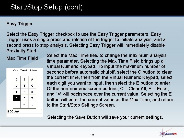
Start/Stop Setup (cont) Easy Trigger Select the Easy Trigger checkbox to use the Easy Trigger parameters. Easy Trigger uses a single press and release of the trigger to initiate analysis, and a second press to stop analysis. Selecting Easy Trigger will immediately disable Proximity Start. Select the Max Time field to change the maximum analysis Max Time Field time parameter. Selecting the Max Time Field brings up a Virtual Numeric Keypad. To input the maximum number of seconds before automatic shutoff, select the C button to clear the current time, then from the Virtual Numeric Keypad, select each digit you want to input, then select the E button to enter. Of the non numeric screen buttons, C = Clear All, E = Enter, and “<" will backspace over the current value. Selecting the E button will enter the current value as the Max Time, and return to the Start/Stop Settings Screen. Selecting the Save Button will save your current settings. 138

Changing Precision (Sigma Value) Sigma is the symbol used for Standard Deviation, a measure of how much a set of numbers deviates from the mean. For example, each of the three data sets {0, 0, 14, and 14}, {0, 6, 8, and 14} and {6, 6, 8, 8} has a mean of 7. Their standard deviations are 7, 5, and 1, respectively. The third set has a much smaller standard deviation than the other two because its values are all close to 7. In a loose sense, the standard deviation tells us how far from the mean the data points tend to be. The number of standard deviations between the process mean and the nearest specification limit is given in sigmas. As process standard deviation goes up, or the mean of the process moves away from the center of the tolerance, the sigma number goes down, because fewer standard deviations will then fit between the mean and the nearest specification limit. 139

Changing Precision (Sigma Value) (cont) Confidence Intervals Confidence intervals assume that the data are from an approximately normally distributed population generally, sums of many independent, identically distributed random variables tend towards the normal distribution as a limit. Using this assumption, about 68 % of the values must be within 1 standard deviation of the mean, about 95 % of the values must be within two standard deviations, about 99. 7 % must lie within 3 standard deviations, and about 99. 99% of the values must lie within 4 standard deviations. The greater the sigma value of the test, the more confident you can be that the sample is as it appears, but the more difficult and time consuming the testing must be to verify this. That's why it's important to use the most appropriate sigma value for the test. By adjusting the sigma value for each type of test, you can optimize the process for your needs. 140

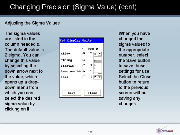
Changing Precision (Sigma Value) (cont) Adjusting the Sigma Values The sigma values are listed in the column headed s. The default value is 2 sigma. You can change this value by selecting the down arrow next to the value, which opens up a drop down menu from which you can select the desired sigma value by clicking on it. When you have changed the sigma values to the appropriate number, select the Save button to save these settings for use. Select the Close button to return to the previous screen without saving any changes. 141

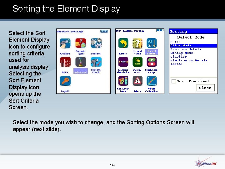
Sorting the Element Display Select the Sort Element Display icon to configure sorting criteria used for analysis display. Selecting the Sort Element Display icon opens up the Sort Criteria Screen. . Select the mode you wish to change, and the Sorting Options Screen will appear (next slide). 142

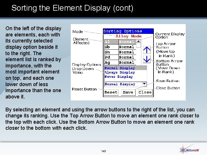
Sorting the Element Display (cont) On the left of the display are elements, each with its currently selected display option beside it to the right. The element list is ranked by importance, with the most important element on top, and each one lower down of less importance than the one above it. . By selecting an element and using the arrow buttons to the right of the list, you can change its ranking. Use the Top Arrow Button to move an element one rank closer to the top with each click. Use the Bottom Arrow Button to move an element one rank closer to the bottom with each click. 143

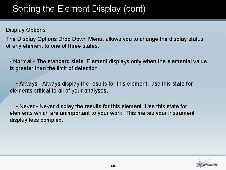
Sorting the Element Display (cont) Display Options The Display Options Drop Down Menu, allows you to change the display status . of any element to one of three states: • Normal The standard state. Element displays only when the elemental value is greater than the limit of detection. • Always display the results for this element. Use this state for elements critical to all of your analyses. • Never display the results for this element. Use this state for elements which are unimportant to your work. This makes your instrument display less complex. 144

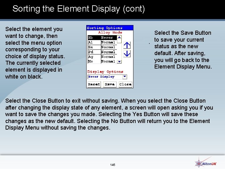
Sorting the Element Display (cont) Select the element you want to change, then select the menu option corresponding to your choice of display status. The currently selected element is displayed in white on black. Select the Save Button . to save your current status as the new default. After saving, you will go back to the Element Display Menu. Select the Close Button to exit without saving. When you select the Close Button after changing the display state of any element, a screen will open asking you if you want to save the changes you made. Selecting the Yes Button will save these changes as the new default. Selecting the No Button will return you to the Element Display Menu without saving the changes. 145

Alloy Libraries • Upload libraries from your computer to your analyser • Download libraries from your analyser to your computer • Open multiple libraries and cut and paste between them • Edit alloy definitions within a library • Print libraries and individual alloys in a library • Save, Rename, and Delete libraries. You can have only one primary Alloy Library and one additional Library active on your analyser at any one time. you have two identical copies of the 800 library loaded. You may edit the libraries as you wish, though it is a good practice to rename edited libraries. You can store as may as you need to on your computer, and upload/download as needed. 146

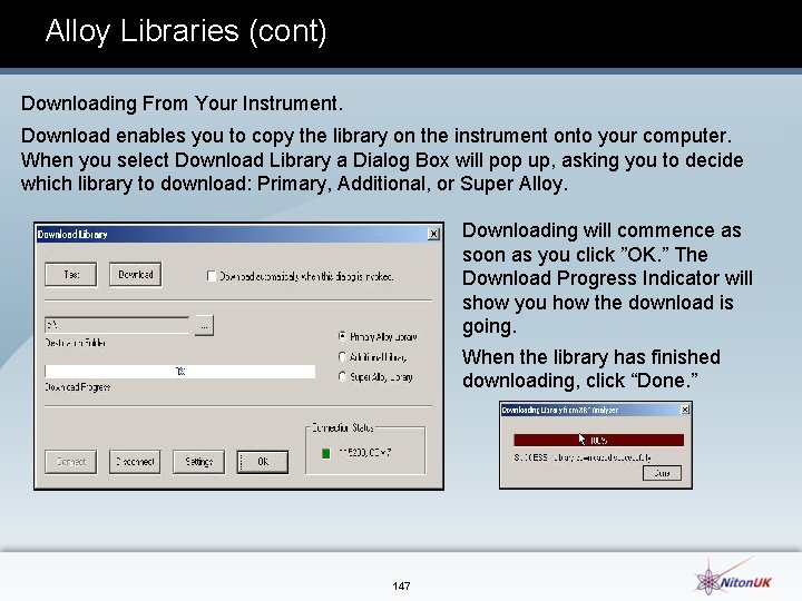
Alloy Libraries (cont) Downloading From Your Instrument. Download enables you to copy the library on the instrument onto your computer. When you select Download Library a Dialog Box will pop up, asking you to decide which library to download: Primary, Additional, or Super Alloy. Downloading will commence as soon as you click ”OK. ” The Download Progress Indicator will show you how the download is going. When the library has finished downloading, click “Done. ” 147

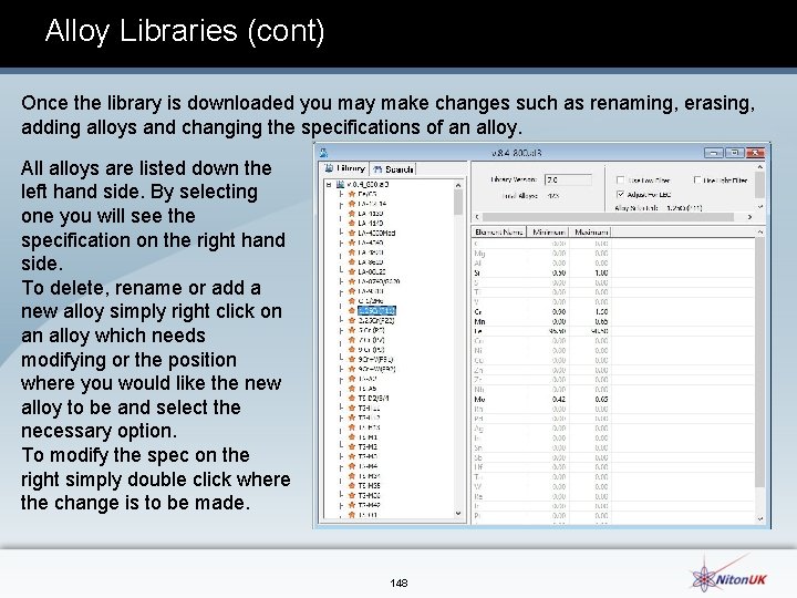
Alloy Libraries (cont) Once the library is downloaded you may make changes such as renaming, erasing, adding alloys and changing the specifications of an alloy. All alloys are listed down the left hand side. By selecting one you will see the specification on the right hand side. To delete, rename or add a new alloy simply right click on an alloy which needs modifying or the position where you would like the new alloy to be and select the necessary option. To modify the spec on the right simply double click where the change is to be made. 148

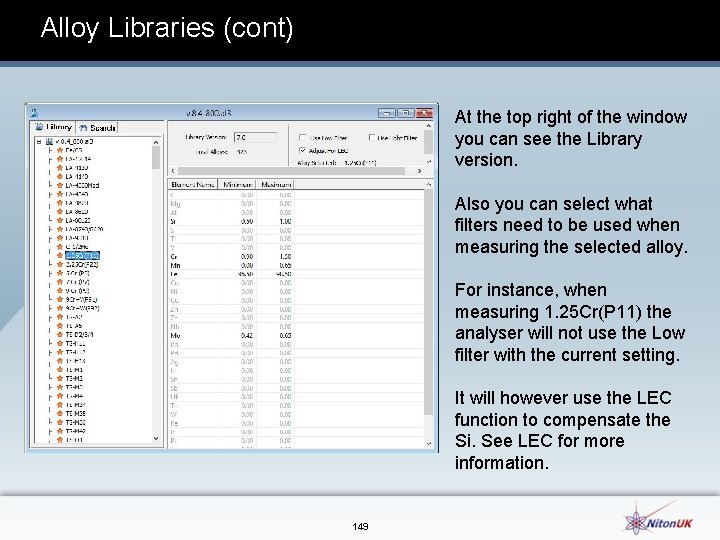
Alloy Libraries (cont) At the top right of the window you can see the Library version. Also you can select what filters need to be used when measuring the selected alloy. For instance, when measuring 1. 25 Cr(P 11) the analyser will not use the Low filter with the current setting. It will however use the LEC function to compensate the Si. See LEC for more information. 149

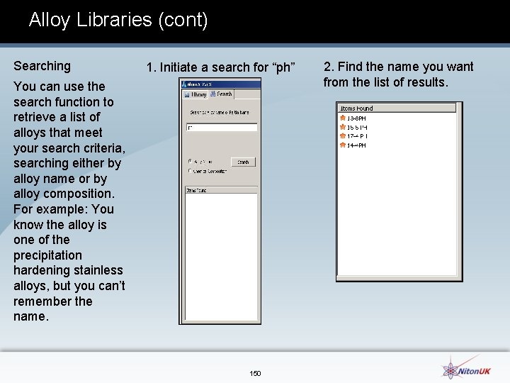
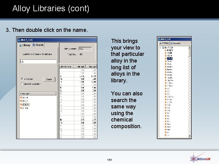
Alloy Libraries (cont) Searching 1. Initiate a search for “ph” You can use the search function to retrieve a list of alloys that meet your search criteria, searching either by alloy name or by alloy composition. For example: You know the alloy is one of the precipitation hardening stainless alloys, but you can’t remember the name. 150 2. Find the name you want from the list of results.

Alloy Libraries (cont) 3. Then double click on the name. This brings your view to that particular alloy in the long list of alloys in the library. You can also search the same way using the chemical composition. 151

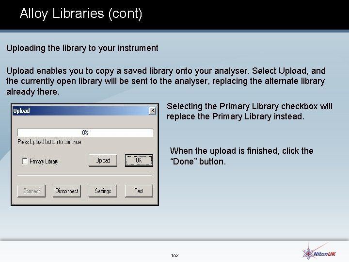
Alloy Libraries (cont) Uploading the library to your instrument Upload enables you to copy a saved library onto your analyser. Select Upload, and the currently open library will be sent to the analyser, replacing the alternate library already there. Selecting the Primary Library checkbox will replace the Primary Library instead. When the upload is finished, click the “Done” button. 152

LEC (Light Element Correction) The Light Element Correction (LEC) is a feature which is available on your analyser. This corrects for bias caused by light undetected elements that cause detected elements to read high when the results are normalized to 100%. Using LEC, the values entered for LE content are proportionately deducted from the normalized values to provide unbiased element values, as well as a display of the nominal value for the LE content. This provides more accurate results when LE content is present above 1%. Using this feature requires that the user enter the light element values (Si, S, Al, P and Mg) to the alloy specification into the NDT Alloy Grade Library. Then the ‘Adjust for LEC’ box is checked for that alloy. Now when that alloy is measured with the analyser it will move that combined light element value away from the main analysis result correcting all the other elements. 153
 200+400+600
 Torno cnc gsk 980 tdc
 Express 4,980,000, 000 in scientific notation.
 Oki error 980
 Frases de avicena
 How many significant figures in 980
 Aa 980
 Tatoucps
 Covidien puritan bennett 980 series ventilator
 T junction english bond
 Course title and course number
 Course interne course externe
 Cognitive stimulation therapy training course
 Module 7 weights and measures
 Total army sponsorship training course
 Adventurer basic staff training course pdf
 Cabin crew training course in malaysia
 Winter driving safety presentation
 Cognitive stimulation therapy training course
 Fda clinical investigator training course
 Autotransfusion training course
 Ufr dose prismaflex
 Jet reports training course
 Pd
Pd Pto course
 Pfmea training course
 Asbmt clinical research training course
 Account reconciliation course
 Analytical thinking training course outline
 Responsible beverage server
 Accounts payable training course
 High bias low variance
 V
V Training is expensive without training it is more expensive
 Perbedaan on the job training dan off the job training
 Aggression replacement training facilitator training
 400 ün yüzde 15 i
 A 190 000 w engine can accelerate
 Dts garage
 Is usp 800 mandatory
 Niton xl 800
 Nist sp 800-14
 Swingline heavy duty tacker 800
 Nist 800-73
 Sgt 800
 67x10^6 in scientific notation
 Cpec usp 800
 Roc800
 Ben earns $12 800 a year
 Ary pierwszej klasy
 Wac 296-800-160
 800*76
 800 * 26
 1-800-881-0722
 800/18000
 Performance measurement guide for information security
 Nist 800-57
 What is x.800
 Nist sp 800 16
 Danelaw area
 800-660-6212
 Pxrxt
Pxrxt Abitur 400 punkte
 Abitur punkte nrw
 Formada por morros pontiagudos cristas
 Everest 800
 Dewey decimal 500
 Dealership compliance training
 Gml 800
 Zappos value proposition
 Utilizari alchine
 Z punktów a i b odległych od siebie o 800
 6 types of simple machines examples
 Out of 800 families with 4
 Heptarchy
 Gaya yang besarnya 50 dyne menimbulkan tekanan
 Luas permukaan sebuah tabung adalah 880 cm
 Ano ang round off ng 56
 Nist sp 800-55
 Aastra 800
 Nia 800
 Arsitektur keamanan osi
 Is 800: 2007
 Atlas 800 (model 3010)
 Promat monolux
 Wellsoffice wellsfargo com ceo signon
 8005427793
 Britain 800 ad
 10 a yuvarlanan en küçük sayı
 Nist 800-20
 Motorola tsch
 แบบจำลอง
 Convert 800 km to miles
 400-800 nm
 Usp 800 summary
 Nist 800-14
 Nist 800-64
 Design of gantry girder as per is 800 2007
 Gambar titik sudut
 Ge mac 800
 800 pixels wide and 200 pixels tall pictures
 640 en yakın yüzlüğe yuvarlama
 100 200 300 400 500
 Nist 800-14
 800 456 3355
 1 to 800 numbers chart
 800-644-6292
 Dts garage motor
 Reading inventory score chart
 Momen gaya dimensi
 How do engineers use scientific notation
 A+202:2=800
 Acrastrip 800
 Manulife strp
 Nia 800-899 areas especializadas
 800-955-7615
 63 entre 3
 Metaxalone 1600 mg
 Desunin 800
 Zakladatel franskej rise
 Gilian 800
 Karol velky 800
 Pure vs partial e commerce
 A+202:2=800
 Peer entity authentication and data origin authentication
 02 2235
 Alsa solar systems llc
 Eec67300
 Radio emission codes
 Jika mesin mengambil panas 1000 j
 Roman numerals n
 Pm 800
 Gabapentin 400 mg capsule picture
 800/18000
 800/18000
 Trabant 800 rs
 Poeti provenzali dell'800
 Evoluzione del romanzo dall'800 al 900
 8006631463
 U tube manometer formula
 35 as a fraction
 Crypto
 800-1150
 Who enforces usp 800
 800+600+400
 1-800-677-1116
 Ccs 800
 It fw
It fw 800-7721213
 800/18000
 800/18000
 800/18000
 Gmx 800 magnetic fluid conditioner
 Meter liter gram

