
Training Birdie Stefan Rudat 1 ATeco M Gmb

Training Birdie Stefan Rudat 1 ATeco. M Gmb. H 06/10/2008
Agenda l <Overview> – < Front Panel > l <Short flashback Network Protocols > – – – l < Ethernet Basics > < IP Header > < VLAN > < IGMP > < RTP > <MPEG - TS over IP> – < Forward Error Correction 1 D / 2 D > – < FEC Overhead > l <Birdie license Model > 2 ATeco. M Gmb. H 06/10/2008
Agenda l <hands on> – < Setup Ethernet IP > – < Setup ASI Output session > – < Setup ASI Input session > l < Web GUI> ★ no slides live introduction l < OPSH > l < Troubleshooting> ★ no slides live introduction 3 ATeco. M Gmb. H 06/10/2008
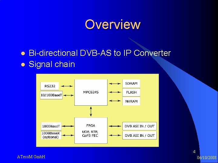
Overview l l Bi-directional DVB-AS to IP Converter Signal chain 4 ATeco. M Gmb. H 06/10/2008
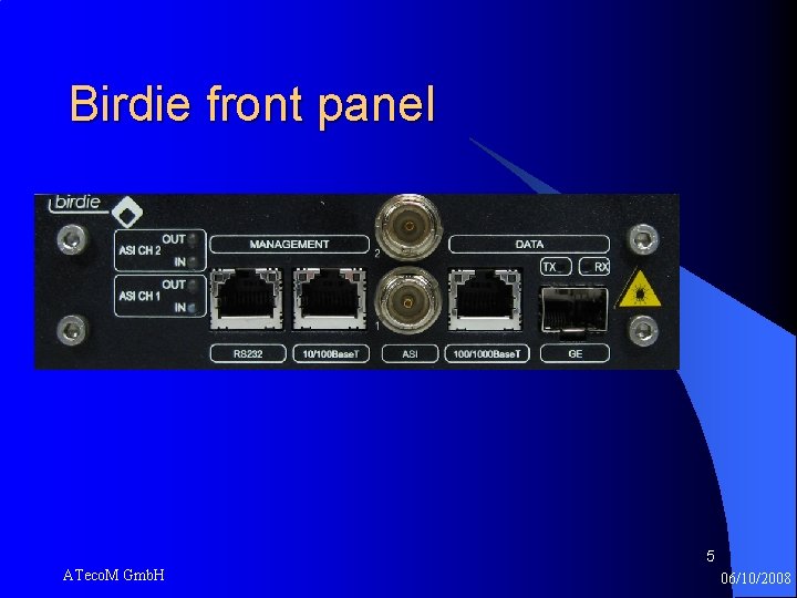
Birdie front panel 5 ATeco. M Gmb. H 06/10/2008
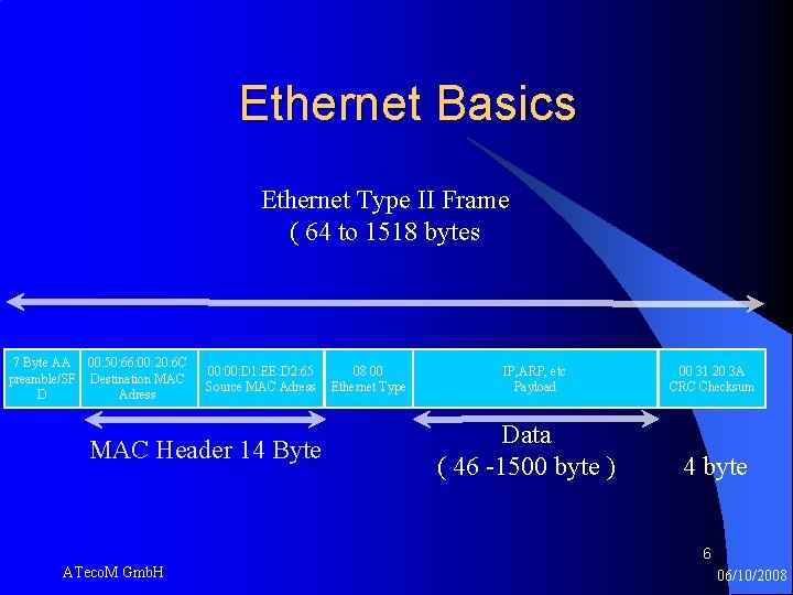
Ethernet Basics Ethernet Type II Frame ( 64 to 1518 bytes 7 Byte AA 00: 50: 66: 00: 20: 6 C preamble/SF Destination MAC D Adress 00: D 1: EE: D 2: 65 Source MAC Adress MAC Header 14 Byte 08 00 Ethernet Type IP, ARP, etc Payload Data ( 46 -1500 byte ) 00 31 20 3 A CRC Checksum 4 byte 6 ATeco. M Gmb. H 06/10/2008
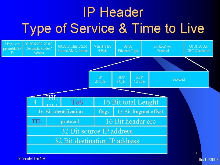
IP Header Type of Service & Time to Live 7 Byte AA 00: 50: 66: 00: 20: 6 C preamble/SF Destination MAC D Adress 00: D 1: EE: D 2: 65 Source MAC Adress Vl. AN-TAG 4 Byte IP 20 byte 4 IHL HLl To. S 16 Bit Identification TTL 08 00 Ethernet Type UDP 8 byte IP, ARP, etc Payload RTP 12 byte 00 31 20 3 A CRC Checksum Payload 16 Bit total Lenght flags 13 Bit fragmet offset 16 Bit header crc 32 Bit source IP address 32 Bit destination IP address protocol 7 7 ATeco. M Gmb. H 06/10/2008
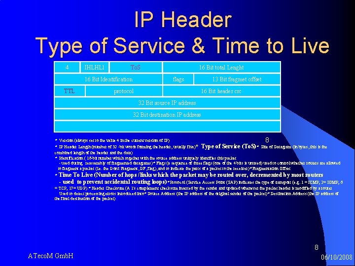
IP Header Type of Service & Time to Live 4 IHLHLl To. S 16 Bit Identification TTL 16 Bit total Lenght flags protocol 13 Bit fragmet offset 16 Bit header crc 32 Bit source IP address 32 Bit destination IP address * Version (always set to the value 4 in the current version of IP) 8 * IP Header Length (number of 32 -bit words forming the header, usually five)* Type of Service (To. S)* Size of Datagram (in bytes, this is the combined length of the header and the data) * Identification ( 16 -bit number which together with the source address uniquely identifies this packet - used during reassembly of fragmented datagrams)* Flags (a sequence of three flags (one of the 4 bits is unused) used to control whether routers are allowed to fragment a packet (i. e. the Don't Fragment, DF, flag), and to indicate the parts of a packet to the receiver)* Fragmentation Offset * Time To Live (Number of hops /links which the packet may be routed over, decremented by most routers - used to prevent accidental routing loops)* Protocol (Service Access Point (SAP) indicates the type of transport (e. g. 1 = ICMP; 2= IGMP; 6 = TCP; 17= UDP). * Header Checksum (A 1's complement checksum inserted by the sender and updated whenever the packet header is modified by a router Used to detect processing errors introduced into* Source Address (the IP address of the original sender of the packet)* Destination Address (the IP address of the final destination of the packet) 8 ATeco. M Gmb. H 06/10/2008
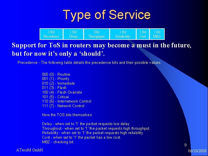
Type of Service 3 Bit Precedence 1 Bit Delay 1 Bit Throughput 1 Bit Reliability 1 Bit Cost 1 Bit MBZ Support for To. S in routers may become a must in the future, but for now it’s only a ‘should’. Precedence - The following table details the precedence bits and their possible values: 000 (0) - Routine 001 (1) - Priority 010 (2) - Immediate 011 (3) - Flash 100 (4) - Flash Override 101 (5) - Critical 110 (6) - Internetwork Control 111 (7) - Network Control Now the TOS bits themselves: Delay - when set to '1' the packet requests low delay. Throughout - when set to '1' the packet requests high throughput. Reliability - when set to '1' the packet requests high reliability. Cost - when set to '1' the packet has a low cost. MBZ - checking bit. ATeco. M Gmb. H 9 06/10/2008
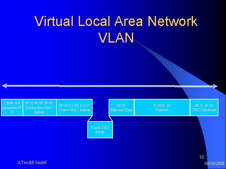
Virtual Local Area Network VLAN 7 Byte AA 00: 50: 66: 00: 20: 6 C preamble/SF Destination MAC D Adress 00: D 1: EE: D 2: 65 Source MAC Adress 08 00 Ethernet Type IP, ARP, etc Payload 00 31 20 3 A CRC Checksum Vl. AN-TAG 4 Byte 10 ATeco. M Gmb. H 06/10/2008
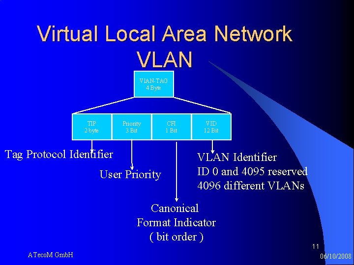
Virtual Local Area Network VLAN Vl. AN-TAG 4 Byte TIP 2 byte Priority 3 Bit Tag Protocol Identifier User Priority CFI 1 Bit VID 12 Bit VLAN Identifier ID 0 and 4095 reserved 4096 different VLANs Canonical Format Indicator ( bit order ) ATeco. M Gmb. H 11 06/10/2008
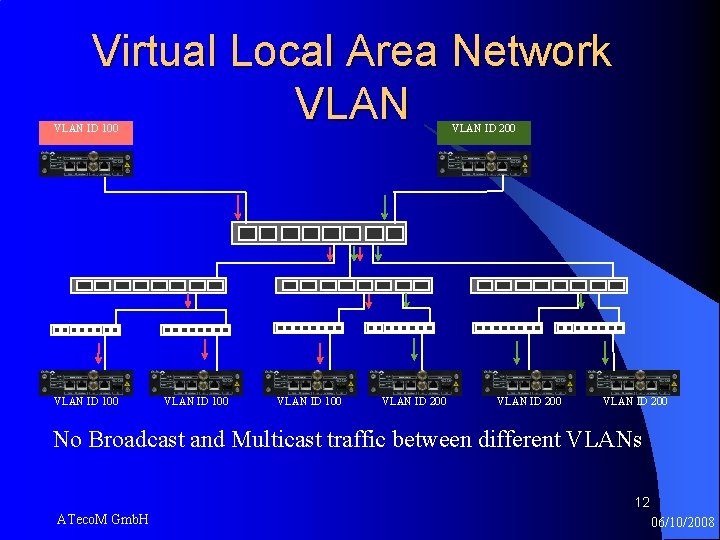
Virtual Local Area Network VLAN ID 100 VLAN ID 200 VLAN ID 200 No Broadcast and Multicast traffic between different VLANs 12 ATeco. M Gmb. H 06/10/2008
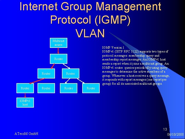
Internet Group Management Protocol (IGMP) VLAN Multicast source IGMP Version 1 IGMPv 1 (IETF RFC 1122) supports two types of protocol messages: membership query and membership report messages. An IGMPv 1 host sends a report when it joins a multicast group. An IGMPv 1 router queries periodically using query messages to determine the active members of a group. Whenever a host receives a query message, it responds with report messages (one report per group) for all its associated multicast groups. Router Router IGMPv 1 host 13 ATeco. M Gmb. H 06/10/2008
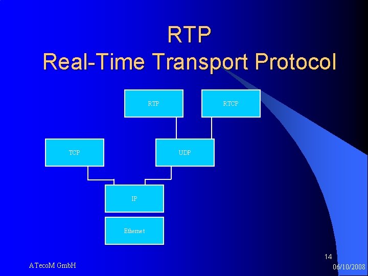
RTP Real-Time Transport Protocol RTP TCP RTCP UDP IP Ethernet 14 ATeco. M Gmb. H 06/10/2008
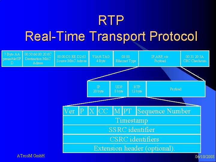
RTP Real-Time Transport Protocol 7 Byte AA 00: 50: 66: 00: 20: 6 C preamble/SF Destination MAC D Adress 00: D 1: EE: D 2: 65 Source MAC Adress Vl. AN-TAG 4 Byte IP 20 byte 08 00 Ethernet Type UDP 8 byte RTP 12 byte IP, ARP, etc Payload 00 31 20 3 A CRC Checksum Payload Ver P X CC M PT Sequence Number Timestamp SSRC identifier CSRC identifiers Extension header (optional). 15 ATeco. M Gmb. H 06/10/2008
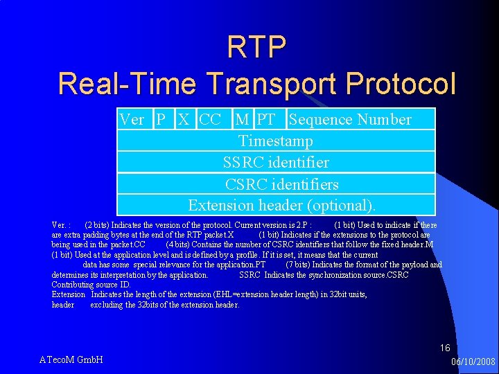
RTP Real-Time Transport Protocol Ver P X CC M PT Sequence Number Timestamp SSRC identifier CSRC identifiers Extension header (optional). 16 Ver. : (2 bits) Indicates the version of the protocol. Current version is 2. P : (1 bit) Used to indicate if there are extra padding bytes at the end of the RTP packet. X (1 bit) Indicates if the extensions to the protocol are being used in the packet. CC (4 bits) Contains the number of CSRC identifiers that follow the fixed header. M (1 bit) Used at the application level and is defined by a profile. If it is set, it means that the current data has some special relevance for the application. PT (7 bits) Indicates the format of the payload and determines its interpretation by the application. SSRC Indicates the synchronization source. CSRC Contributing source ID. Extension Indicates the length of the extension (EHL=extension header length) in 32 bit units, header excluding the 32 bits of the extension header. 16 ATeco. M Gmb. H 06/10/2008
RTP ➡used for the transport of real-time data, including audio and video includes: • timing reconsruction • loss detection • security and content identification ➡RTP does not address resource reservation ➡does not guarantee quality-of-service for real time services 17 ATeco. M Gmb. H 06/10/2008
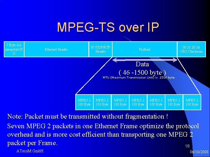
MPEG-TS over IP 7 Byte AA preamble/SF D IP /UDP/RTP Header Ethernet Header 00 31 20 3 A CRC Checksum Payload Data ( 46 -1500 byte ) MTU (Maximum Transmission Unit) is 1500 byte MPEG 2 188 Byte MPEG 2 188 Byte Note: Packet must be transmitted without fragmentation ! Seven MPEG 2 packets in one Ethernet Frame optimize the protocol overhead and is more cost efficient than transporting one MPEG 2 packet per Frame. 18 ATeco. M Gmb. H 06/10/2008
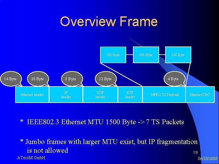
Overview Frame 188 Byte 14 Byte 20 Byte Ethernet header 8 Byte IP header 188 Byte 12 Byte UDP header 188 Byte 4 Byte RTP header MPEG TS Payload Ethernet CRC * IEEE 802. 3 Ethernet MTU 1500 Byte -> 7 TS Packets * Jumbo frames with larger MTU exist, but IP fragmentation is not allowed 19 ATeco. M Gmb. H 06/10/2008
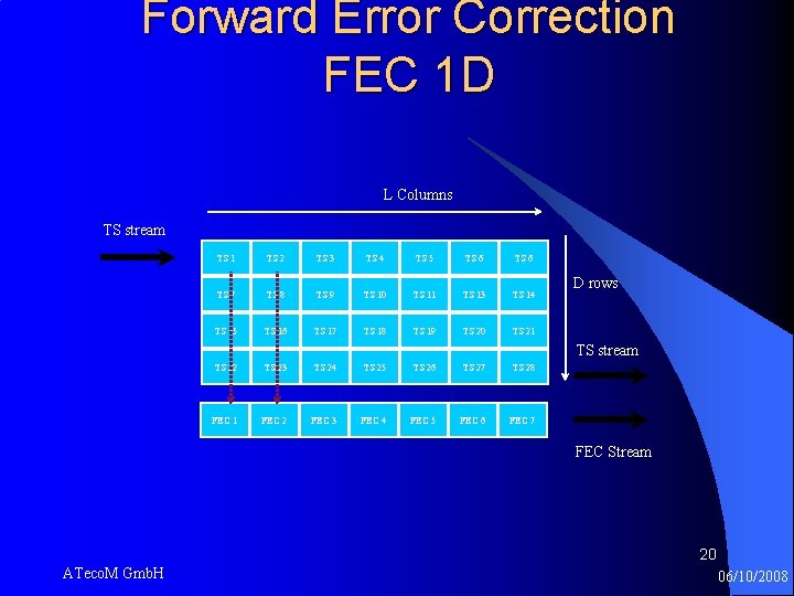
Forward Error Correction FEC 1 D L Columns TS stream TS 1 TS 2 TS 3 TS 4 TS 5 TS 6 TS 7 TS 8 TS 9 TS 10 TS 11 TS 13 TS 14 TS 15 TS 16 TS 17 TS 18 TS 19 TS 20 TS 21 TS 22 TS 23 TS 24 TS 25 TS 26 TS 27 TS 28 FEC 1 FEC 2 FEC 3 FEC 4 FEC 5 FEC 6 FEC 7 D rows TS stream FEC Stream 20 ATeco. M Gmb. H 06/10/2008
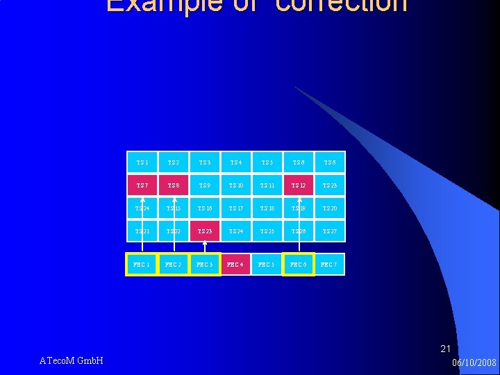
Example of correction TS 1 TS 2 TS 3 TS 4 TS 5 TS 6 TS 7 TS 8 TS 9 TS 10 TS 11 TS 12 TS 23 TS 24 TS 15 TS 16 TS 17 TS 18 TS 19 TS 20 TS 21 TS 22 TS 23 TS 24 TS 25 TS 26 TS 27 FEC 1 FEC 2 FEC 3 FEC 4 FEC 5 FEC 6 FEC 7 21 ATeco. M Gmb. H 06/10/2008
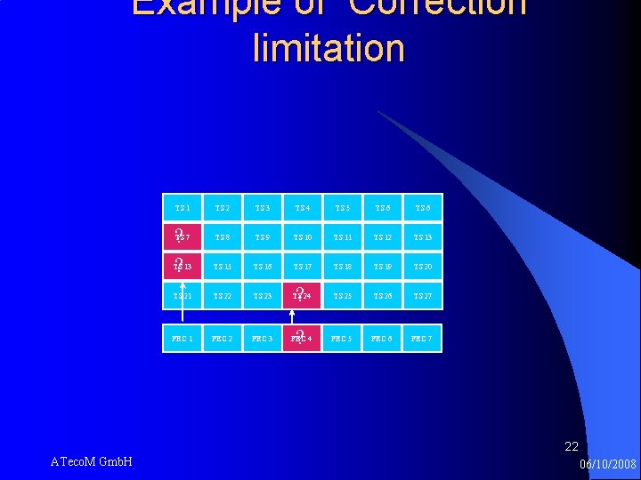
Example of Correction limitation TS 1 TS 2 TS 3 TS 4 TS 5 TS 6 TS 7 TS 8 TS 9 TS 10 TS 11 TS 12 TS 13 TS 15 TS 16 TS 17 TS 18 TS 19 TS 20 TS 21 TS 22 TS 23 TS 24 ? TS 25 TS 26 TS 27 FEC 1 FEC 2 FEC 3 FEC 4 ? FEC 5 FEC 6 FEC 7 ? ? 22 ATeco. M Gmb. H 06/10/2008
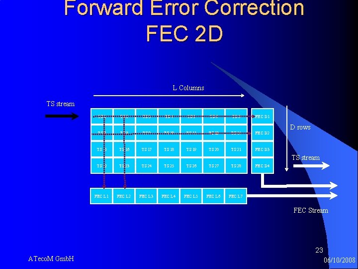
Forward Error Correction FEC 2 D L Columns TS stream TS 1 TS 2 TS 3 TS 4 TS 5 TS 6 FEC D 1 TS 7 TS 8 TS 9 TS 10 TS 11 TS 13 TS 14 FEC D 2 TS 15 TS 16 TS 17 TS 18 TS 19 TS 20 TS 21 FEC D 3 TS 22 TS 23 TS 24 TS 25 TS 26 TS 27 TS 28 FEC D 4 FEC L 1 FEC L 2 FEC L 3 FEC L 4 FEC L 5 FEC L 6 FEC L 7 D rows TS stream FEC Stream 23 ATeco. M Gmb. H 06/10/2008
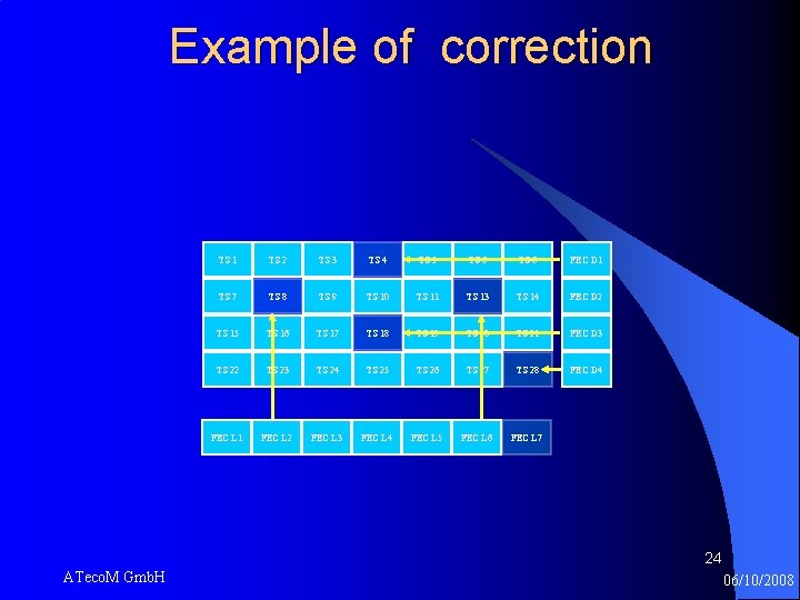
Example of correction TS 1 TS 2 TS 3 TS 4 TS 5 TS 6 FEC D 1 TS 7 TS 8 TS 9 TS 10 TS 11 TS 13 TS 14 FEC D 2 TS 15 TS 16 TS 17 TS 18 TS 19 TS 20 TS 21 FEC D 3 TS 22 TS 23 TS 24 TS 25 TS 26 TS 27 TS 28 FEC D 4 FEC L 1 FEC L 2 FEC L 3 FEC L 4 FEC L 5 FEC L 6 FEC L 7 24 ATeco. M Gmb. H 06/10/2008
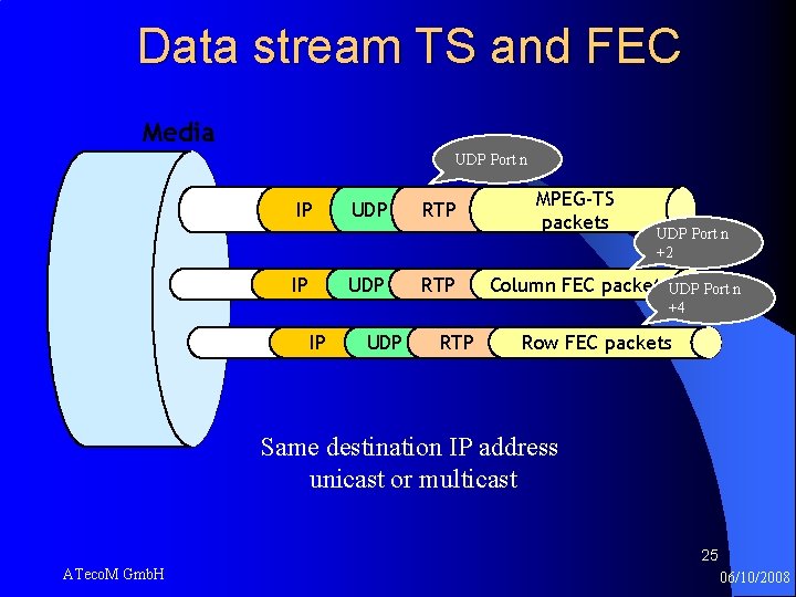
Data stream TS and FEC Media UDP Port n IP IP UDP RTP MPEG-TS packets UDP Port n +2 Column FEC packets. UDP Port n +4 IP UDP RTP Row FEC packets Same destination IP address unicast or multicast 25 ATeco. M Gmb. H 06/10/2008
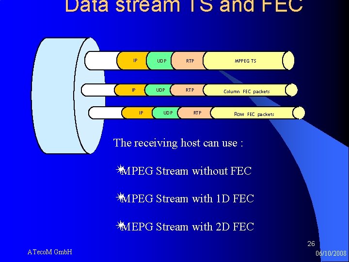
Data stream TS and FEC IP IP IP UDP RTP MPPEG TS Column FEC packets Row FEC packets The receiving host can use : ✴MPEG Stream without FEC ✴MPEG Stream with 1 D FEC ✴MEPG Stream with 2 D FEC 26 ATeco. M Gmb. H 06/10/2008
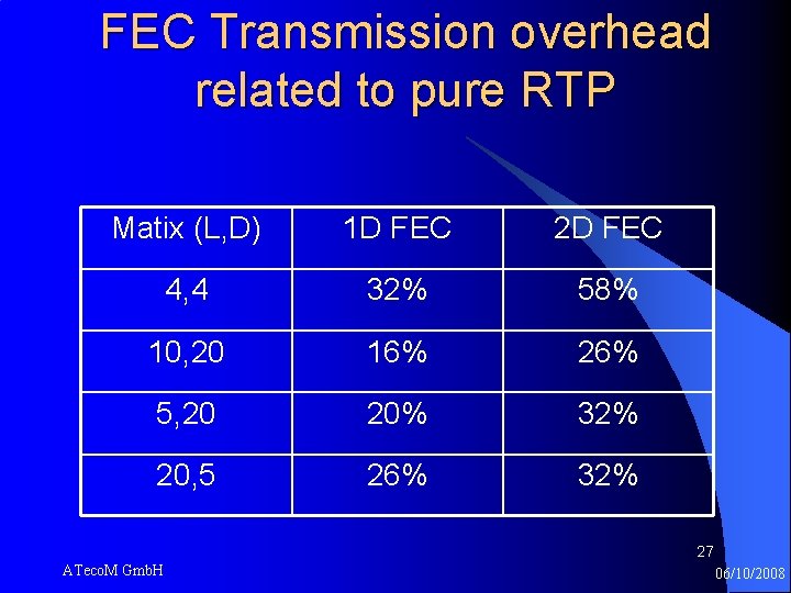
FEC Transmission overhead related to pure RTP Matix (L, D) 1 D FEC 2 D FEC 4, 4 32% 58% 10, 20 16% 26% 5, 20 20% 32% 20, 5 26% 32% 27 ATeco. M Gmb. H 06/10/2008
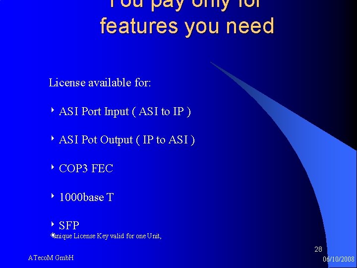
You pay only for features you need License available for: ‣ ASI Port Input ( ASI to IP ) ‣ ASI Pot Output ( IP to ASI ) ‣ COP 3 FEC ‣ 1000 base T ‣ SFP ✴ unique License Key valid for one Unit, 28 ATeco. M Gmb. H 06/10/2008
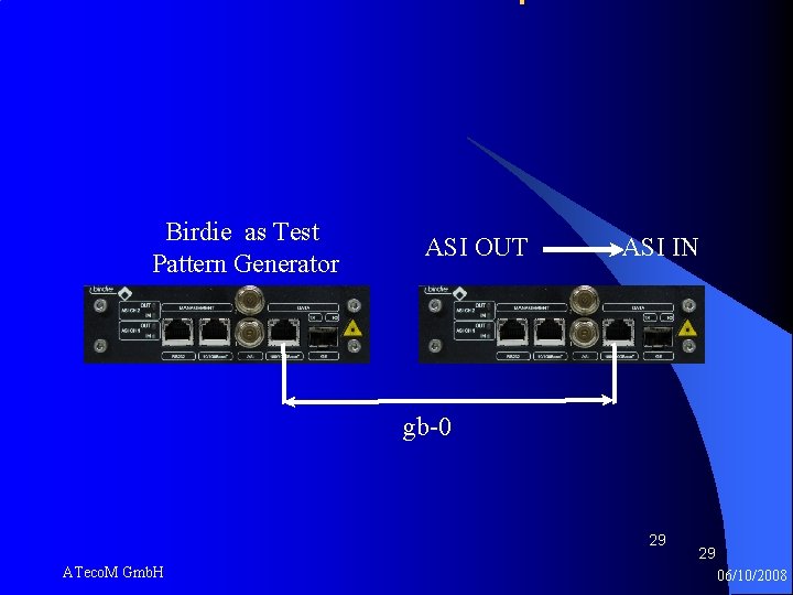
Birdie as Test Pattern Generator ASI OUT ASI IN gb-0 29 ATeco. M Gmb. H 29 06/10/2008
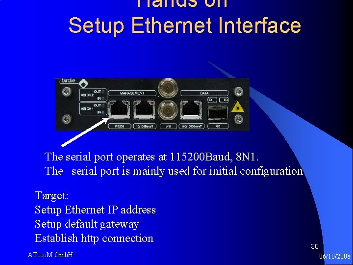
Hands on Setup Ethernet Interface The serial port operates at 115200 Baud, 8 N 1. The serial port is mainly used for initial configuration Target: Setup Ethernet IP address Setup default gateway Establish http connection ATeco. M Gmb. H 30 06/10/2008
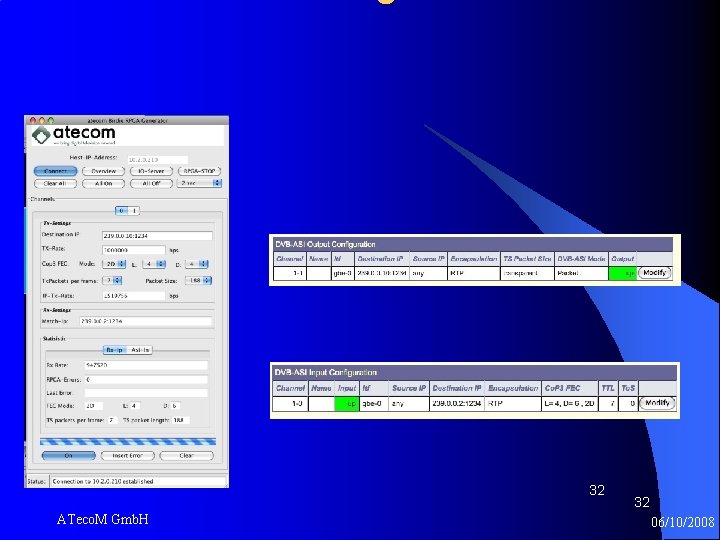
Setup IP to ASI and IP to ASI Target: Setup Gbe-0 IP adress Setup ASI Session for ASI Output Setup ASI Session for ASI Input 31 ATeco. M Gmb. H 06/10/2008
32 ATeco. M Gmb. H 32 06/10/2008
33 ATeco. M Gmb. H 33 06/10/2008
34 ATeco. M Gmb. H 34 06/10/2008
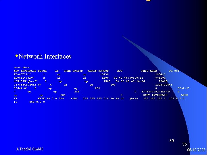
• Network Interfaces >net show NET INTERFACE: DESCR IF OPER-STATUS ADMIN-STATUS MTU PHYS-ADDR TX-OCT RX-OCT"lo" 1 up up 16436 190412"eth 0" 2 up up 1500 00: 50: 66: 00: 20: 6 c 871270 1051075"gbe-0" 3 up up 1500 00: 50: 66: 00: 20: 6 d 98806 2878344372"mt-0" 4 up up 204 1295829668 0"dai-0" 5 up up 204 0 0"mt-1" 7 up up 204 0 1376880792"dao-1" 9 up up 204 0 0 NET INTERFACE: ADDR IF MASK 10. 209 eth 0 255. 010. 10. 10 gbe-0 255. 0 127. 0. 0. 1 lo 255. 0. 0. 0 35 ATeco. M Gmb. H 35 06/10/2008
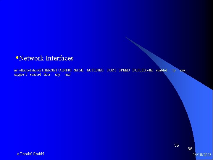
• Network Interfaces net ethernet show. ETHERNET CONFIG: NAME AUTONEG anygbe-0 enabled fibre any PORT SPEED DUPLEX eth 0 enabled tp 36 ATeco. M Gmb. H any 36 06/10/2008
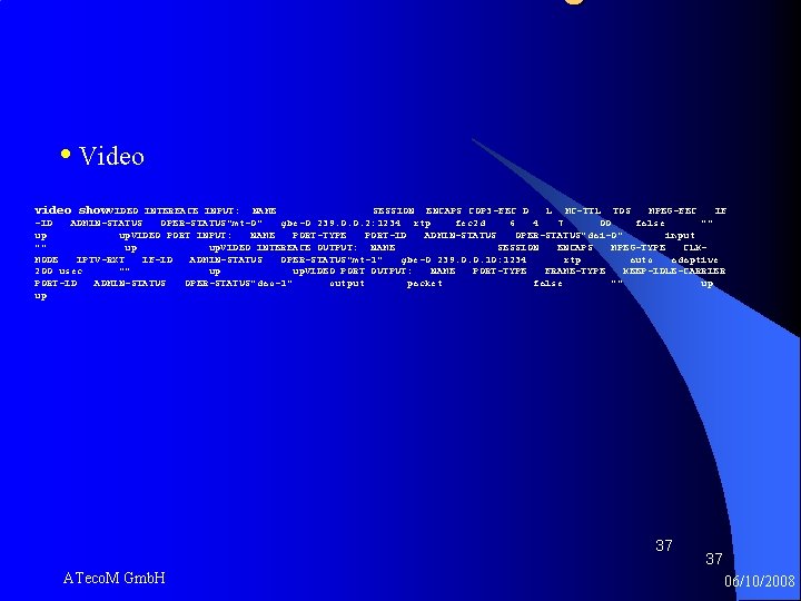
• Video video show. VIDEO INTERFACE INPUT: NAME SESSION ENCAPS COP 3 -FEC D L MC-TTL TOS MPEG-FEC IF -ID ADMIN-STATUS OPER-STATUS"mt-0" gbe-0 239. 0. 0. 2: 1234 rtp fec 2 d 6 4 7 00 false "" up up. VIDEO PORT INPUT: NAME PORT-TYPE PORT-ID ADMIN-STATUS OPER-STATUS"dai-0" input "" up up. VIDEO INTERFACE OUTPUT: NAME SESSION ENCAPS MPEG-TYPE CLKMODE IPTV-RXT IF-ID ADMIN-STATUS OPER-STATUS"mt-1" gbe-0 239. 0. 0. 10: 1234 rtp auto adaptive 200 usec "" up up. VIDEO PORT OUTPUT: NAME PORT-TYPE FRAME-TYPE KEEP-IDLE-CARRIER PORT-ID ADMIN-STATUS OPER-STATUS"dao-1" output packet false "" up up 37 ATeco. M Gmb. H 37 06/10/2008
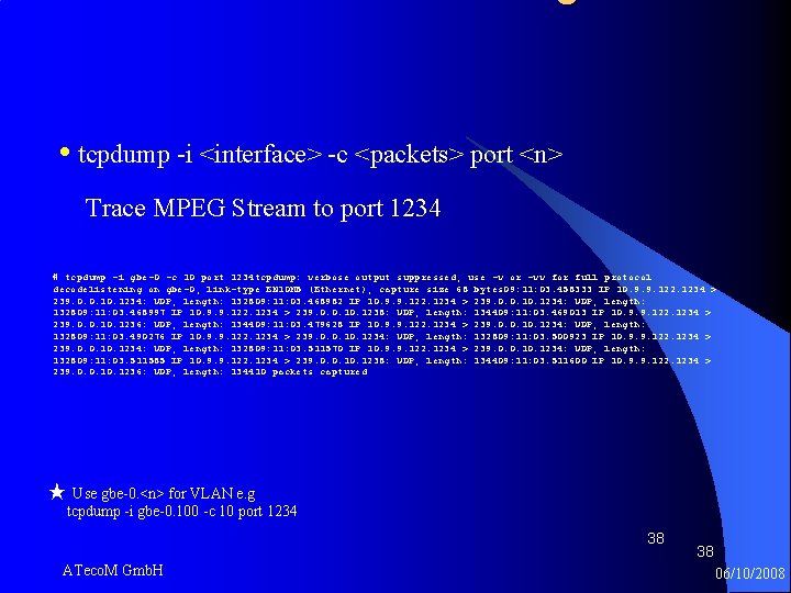
• tcpdump -i <interface> -c <packets> port <n> Trace MPEG Stream to port 1234 # tcpdump -i gbe-0 -c 10 port 1234 tcpdump: verbose output suppressed, use -v or -vv for full protocol decodelistening on gbe-0, link-type EN 10 MB (Ethernet), capture size 68 bytes 09: 11: 03. 458333 IP 10. 9. 9. 122. 1234 > 239. 0. 0. 1234: UDP, length: 132809: 11: 03. 468982 IP 10. 9. 9. 122. 1234 > 239. 0. 0. 1234: UDP, length: 132809: 11: 03. 468997 IP 10. 9. 9. 122. 1234 > 239. 0. 0. 1238: UDP, length: 134409: 11: 03. 469013 IP 10. 9. 9. 122. 1234 > 239. 0. 0. 1236: UDP, length: 134409: 11: 03. 479628 IP 10. 9. 9. 122. 1234 > 239. 0. 0. 1234: UDP, length: 132809: 11: 03. 490276 IP 10. 9. 9. 122. 1234 > 239. 0. 0. 1234: UDP, length: 132809: 11: 03. 500923 IP 10. 9. 9. 122. 1234 > 239. 0. 0. 1234: UDP, length: 132809: 11: 03. 511570 IP 10. 9. 9. 122. 1234 > 239. 0. 0. 1234: UDP, length: 132809: 11: 03. 511585 IP 10. 9. 9. 122. 1234 > 239. 0. 0. 1238: UDP, length: 134409: 11: 03. 511600 IP 10. 9. 9. 122. 1234 > 239. 0. 0. 1236: UDP, length: 134410 packets captured ★ Use gbe-0. <n> for VLAN e. g tcpdump -i gbe-0. 100 -c 10 port 1234 38 ATeco. M Gmb. H 38 06/10/2008
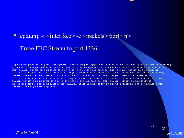
• tcpdump -i <interface> -c <packets> port <n> Trace FEC Stream to port 1236 tcpdump -i gbe-0 -c 10 port 1236 tcpdump: verbose output suppressed, use -v or -vv for full protocol decodelistening on gbe-0, link-type EN 10 MB (Ethernet), capture size 68 bytes 09: 15: 14. 836835 IP 10. 9. 9. 122. 1234 > 239. 0. 0. 1236: UDP, length: 134409: 15: 14. 879428 IP 10. 9. 9. 122. 1234 > 239. 0. 0. 1236: UDP, length: 134409: 15: 14. 922016 IP 10. 9. 9. 122. 1234 > 239. 0. 0. 1236: UDP, length: 134409: 15: 14. 964606 IP 10. 9. 9. 122. 1234 > 239. 0. 0. 1236: UDP, length: 134409: 15. 007199 IP 10. 9. 9. 122. 1234 > 239. 0. 0. 1236: UDP, length: 134409: 15. 049786 IP 10. 9. 9. 122. 1234 > 239. 0. 0. 1236: UDP, length: 134409: 15. 092377 IP 10. 9. 9. 122. 1234 > 239. 0. 0. 1236: UDP, length: 134409: 15. 134970 IP 10. 9. 9. 122. 1234 > 239. 0. 0. 1236: UDP, length: 134409: 15. 177557 IP 10. 9. 9. 122. 1234 > 239. 0. 0. 1236: UDP, length: 134409: 15. 220147 IP 10. 9. 9. 122. 1234 > 239. 0. 0. 1236: UDP, length: 134410 packets captured 39 ATeco. M Gmb. H 39 06/10/2008
- Slides: 39