
TRACK TOLERENCES Master Copy for IRTMTC by IRICEN
TRACK TOLERENCES Master Copy for IRTMTC by IRICEN

TRACK The core function of track is to carry rolling stock. To carry train loads and provide guide path to train. ------------------------- • Safe • Permits safe negotiation by rolling stock • Comfortable Ride • Should not to cause undesirable acceleration

DESIRABLE TRACK QUALITY • Track Performance is judged by Riding comfort, which depends on • Track Geometry parameters • Vehicle Design parameters • Speed of Operation • What are we concerned with? • Track defects which are causing the undesirable accelerations

WHAT IS TRACK MONITORING • Measuring track parameters or Performance • Giving required input or corrective action • Evaluating the output

TRACK GEOMETRY • Each rail has 2 degrees of freedom – Vertical and Lateral • Both the rails, together have 4 degrees of freedom and they define the Track Geometry i. e. • Unevenness • Alignment • Gauge • X-level, Derived Twist

KEY TRACK GEOMETRY PARAMETERS • Unevenness Track irregularity in vertical plane • Alignment Track irregularity in horizontal plane • Gauge Variation in distance between two rails from standard distance of 1676 mm • Twist Change in difference of level of two rails at specified distance
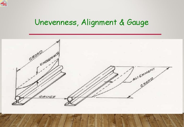
Unevenness, Alignment & Gauge

Gauge & Cross Level

Twist
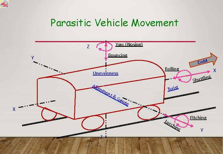
Parasitic Vehicle Movement Yaw (Nosing) Z Bouncing Y Rolling Unevenness Alig nm ent X ling t t u h S Twist &G aug e Pitching Lur chi ng Z Do. M Y X

Nomenclature of Movements Sl. no Movement Nomenclature A) Translational along X axis Shuttling B) Translational along Y axis Lurch C) Translatonal along Z axis Bouncing D) Rotational about X axis Rolling Cross level/ unevenness E) Rotational about Y axis Pitching Unevenness F) Rotational about Z axis Nosing Alignment defect Caused by Loose shunting Alignment defect including gauge variations. Unevenness of rail top
OBJECTIVE OF MEASUREMENT • To identify the deviations or the defects • To compare the existing track standard/desired track parameters with • To monitor the rate of deterioration for special attention • To give timely input and prolong the life of the asset • To assess the quality of track maintenance inputs / the

ASSESSMENT OF TRACK GEOMETRY • Manual Inspection • Push Trolley Inspections • Foot Plate and Brake Van Inspections • Manual Measurements • Measurement of Track parameters manually • Unevenness, Alignment by measuring Versines, Twist by measuring Cross Level, Gauge

LIMITATIONS OF MANUAL MEASUREMENT • Subjective - depends upon human response • Floating Condition • Time Consuming- Slow and tiring • No Continuous record of Track Geometry • Inappropriate for Modern Track Structure and mechanized Maintenance • Not amenable to detailed analysis /
MECHANIZED MEASUREMENT For objective assessment of track quality the following mechanized means are being used on Indian Railways. Ø Track Recording Cars (TRC) – TMM directorate of RDSO – Engineering Department Ø Oscillograph Cars – Mechanical Directorate of RDSO Ø Oscillation Monitoring System (OMS) – Divisions or Zonal Headquartrs
ADVANTAGE OF MECHANISED MEASUREMENT • Objective assessment • Measurement in Loaded Condition • Systematic recording and analysis of data • Fast and convenient • Continuous record of track parameters
PRESENTATION OF MEASUREMENTS • Peak Based ØIt helps in identifying isolated localized defects ØIt helps in isolated attentions • Standard Deviation (SD) Based ØIt helps in identifying bad stretch ØIt is useful in deciding machine maintenance
SD AND PEAK BASED ASSEESSMENT • Less value of SD for any parameter indicates less variation and more uniform track profile. • Uniform track profile results in better riding quality ------------------------------ • SD based index takes into account magnitude of each and every data of vehicle ride while peak based index indicates no. of peaks exceeding a limit without giving an idea of magnitude of various peaks • Peak based index facilitates isolated attention but deployment of machine over long stretches can not be decided.
WHY TRACK TOLERANCE…. . . • It is not practically possible to lay and maintain the track in ideal conditions. • Therefore, some tolerances have been specified to laying and maintaining the track for • Good riding comfort • Safety AND • Longer life of assets • Whenever track parameters are reached to limiting values, maintenance inputs are planned.
TRACK PARAMETER ASSESSMENT • Track parameters can be measured in • Under Loaded Condition - Measured by TRC • Under Floating Condition - Measured manually • These parameters can be measured in two forms- OR • Absolute Value at a location • SD value in some specified stretch.
TRACK TOLERANCES (Measured by TRC under loaded condition) • New Track Tolerance (NTL) • Maintenance Tolerance • Planned Maintenance Limit (PML) • Need Based Maintenance Limit (NBML) • Urgent Maintenance Limit (UML)
PML- PLANNED MAINTENANCE LIMIT • Provides a guidance to plan “Through Tamping” of track in a “Complete Block Section”. These limits if exceeded, track geometry conditions to be analyzed in detail for planning the maintenance. • PML is governed mainly by Riding Quality and defined on the basis of UN and AL defects in terms of Standard Deviation. • Limits are so taken that not more than 10% of track should be worse than this.
NBML- NEED BASED MAINTENANCE LIMIT • These limits are for applying timely correction before the defect size grows to the level of Urgent Maintenance Limit. UML requires a traffic slow down. • These limits are defined for • UN and AL - • Twist and Gauge- in terms of both SD and Peak value in terms of Peak value only. • These attentions are to be applied at Block Level/Spot Level. • Limits are so taken that not more than 50% of track should be worse than this.
UML- URGENT MAINTENANCE LIMIT • These limits are so defined that upon their exceedance, the Discomfort is beyond acceptable limits hence the permitted speed should be slowed down and restored only after attention of Track. • These limits are defined for • Maximum Lateral and Vertical Acceleration • Twist and Gauge in terms of Peak value. • These attentions are to be applied at Spot Level. • Limits are so taken that not more than 90% of track should be worse than this.

SPEED BANDS • Different Track Tolerance Limits have been prescribed for Four different Speed Bands 1. Speed < = 100 Kmph 2. Speed > 100 <= 110 Kmph 3. Speed > 110 <= 130 Kmph 4. Speed > 130 <= 160 Kmph

CHORD LENGTH SN Parameter Short Chord / Base Long Chord/ Base 1 Unevenness 9. 0 (UN-1) 18. 0 (UN-2) 2 Alignment 9. 0 (AL-1) 15. 0 (AL-2) 3 Twist 3. 0 (TW-1) 15. 0 (TW-2)
NEW TRACK TOLERANCE • Highest level of track geometry that can be practically achieved on a new or relayed track with new material. • Nicely laid track results in lesser maintenance inputs & longer life of track assets besides resulting in savings in fuel consumption. • New Track Tolerances have been prescribed under floating as well as under loaded condition and shall be measured three months after the speed is raised to normal
NTL-NEW TRACK TOLERANCE • Under Floating Condition measured manually • To be recorded three months after the speed is raised to normal • Gauge • For Straight including curves of radius upto 350 m and more -5 mm to +3 mm • For curves of radius less than 350 m Upto +10 mm
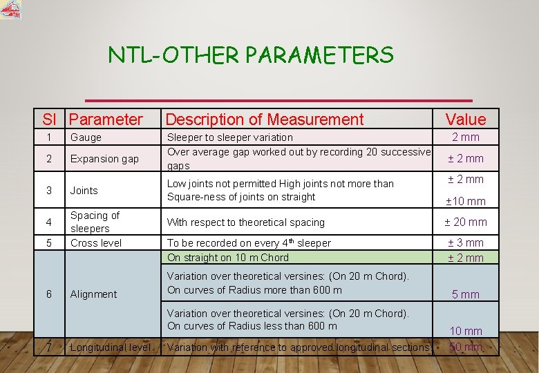
NTL-OTHER PARAMETERS Sl Parameter 1 Gauge 2 Expansion gap 3 4 5 6 Joints Spacing of sleepers Cross level Alignment Description of Measurement Sleeper to sleeper variation Over average gap worked out by recording 20 successive gaps Longitudinal level 2 mm ± 2 mm Low joints not permitted High joints not more than Square-ness of joints on straight ± 10 mm With respect to theoretical spacing ± 20 mm To be recorded on every 4 th sleeper On straight on 10 m Chord ± 3 mm ± 2 mm Variation over theoretical versines: (On 20 m Chord). On curves of Radius more than 600 m Variation over theoretical versines: (On 20 m Chord). On curves of Radius less than 600 m 7 Value Variation with reference to approved longitudinal sections. 5 mm 10 mm 50 mm
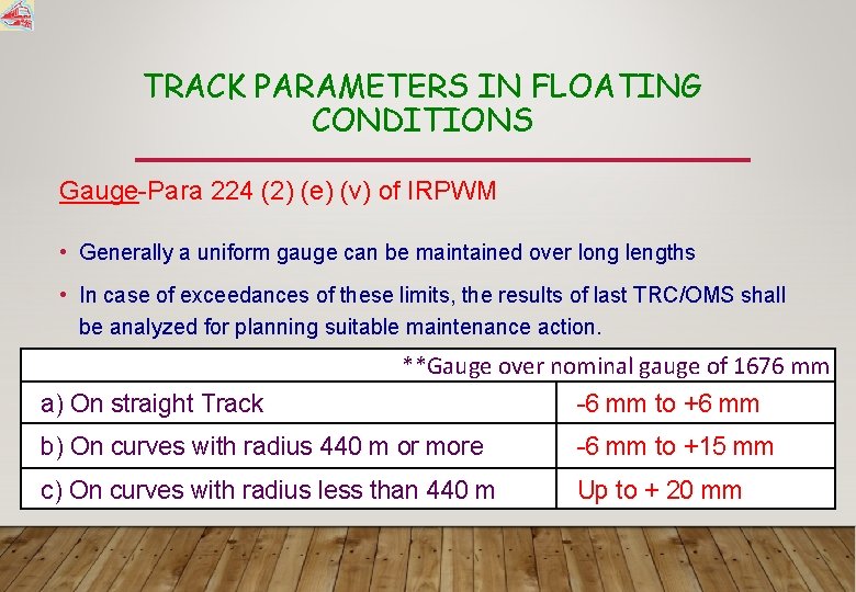
TRACK PARAMETERS IN FLOATING CONDITIONS Gauge-Para 224 (2) (e) (v) of IRPWM • Generally a uniform gauge can be maintained over long lengths • In case of exceedances of these limits, the results of last TRC/OMS shall be analyzed for planning suitable maintenance action. **Gauge over nominal gauge of 1676 mm a) On straight Track -6 mm to +6 mm b) On curves with radius 440 m or more -6 mm to +15 mm c) On curves with radius less than 440 m Up to + 20 mm
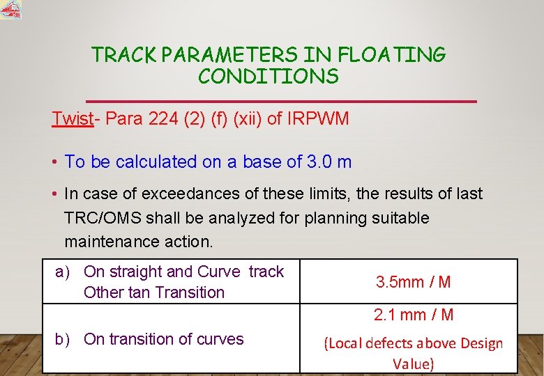
TRACK PARAMETERS IN FLOATING CONDITIONS Twist- Para 224 (2) (f) (xii) of IRPWM • To be calculated on a base of 3. 0 m • In case of exceedances of these limits, the results of last TRC/OMS shall be analyzed for planning suitable maintenance action. a) On straight and Curve track Other tan Transition 3. 5 mm / M 2. 1 mm / M b) On transition of curves (Local defects above Design Value)
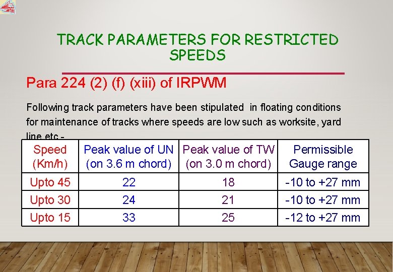
TRACK PARAMETERS FOR RESTRICTED SPEEDS Para 224 (2) (f) (xiii) of IRPWM Following track parameters have been stipulated in floating conditions for maintenance of tracks where speeds are low such as worksite, yard line etc. - Speed (Km/h) Peak value of UN Peak value of TW (on 3. 6 m chord) (on 3. 0 m chord) Permissible Gauge range Upto 45 22 18 -10 to +27 mm Upto 30 24 21 -10 to +27 mm Upto 15 33 25 -12 to +27 mm

SAFETY TOLERANCE • The Safety or stability of train against derailment is governed by Rail wheel interaction and depends upon several factors such as track geometry, vehicle characteristics, speed of the particular vehicle at relevant point of time etc. • Therefore, safety tolerance for track alone cannot be prescribed in Isolation without accounting for other factors. • Safety tolerances for track have not been prescribed on IR. • The tolerances prescribed in IRPWM are for maintaining the track geometry for good riding comfort (Para 607(3) of IRPWM).

SCHEDULE OF DIMENSIONS
WHAT IS SOD ? Schedule of dimension is nothing but a schedule, which lays down : - • Limiting values, recommended values, and infringement to limiting values, which can be continued over entire Indian railways system for various track parameters unless prior sanction has been obtained from the railway board through the CRS to execute works which infringe SOD. • Goods wagon and coaching stock parameters. • Horizontal and vertical clearances to be followed on Indian railways.
NECESSITY OF S O D • It is absolutely essential to ensure safety of traveling public as well as goods over entire Indian railways system. • To adopt uniform system of track tolerances, location of structures and construction standard all over the Indian railways. • To permit different types of coaching and goods stock owned by different railways to ply on entire railway system with same level of degree of safety.
MAIN FEATURES OF SOD-2004 §Dimensions are given only for 1676 mm gauge. §Consists of only metric units. §Only two schedules – schedule I & schedule II §Extra clearances required for curves are modified to suit speed of 160 kmph and SE of 165 mm §Additional appendix for extra clearances required for 200 kmph is also given with 185 mm SE
SCHEDULE - I Schedule I of SOD-2004 consists of those items which are mandatory and have to be observed on all 1676 mm gauge Railways in India. Contains the items of Schedule- I and certain selected items of Schedule- II of 1973 Version

SCHEDULED-1 CONTD. . DIMENSIONS given in Schedule-I are classified under two heads : - §Existing works – The works which were existing before issue of SOD ( 2004 ) and shall be allowed to continue. §New works – Include new constructions, additions of new lines/structure, gauge conversion and doubling and electrification works
SCHEDULE - II Schedule – II contains the existing infringements of Schedule – I which may be permitted to continue on existing railways subjected to such restrictions of speed as considered necessary.
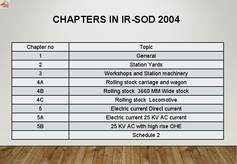
CHAPTERS IN IR-SOD 2004 Chapter no Topic 1 General 2 Station Yards 3 Workshops and Station machinery 4 A Rolling stock carriage and wagon 4 B Rolling stock 3660 MM Wide stock 4 C Rolling stock Locomotive 5 Electric current Direct current 5 A Electric current 25 KV AC current 5 B 25 KV AC with high rise OHE Schedule 2

SOME IMPORTANT DIMENSIONS GIVEN IN SOD For Works Horizontal distance from centre to centre of track For existing works 4265 mm For new works/additions to existing works 5300 mm

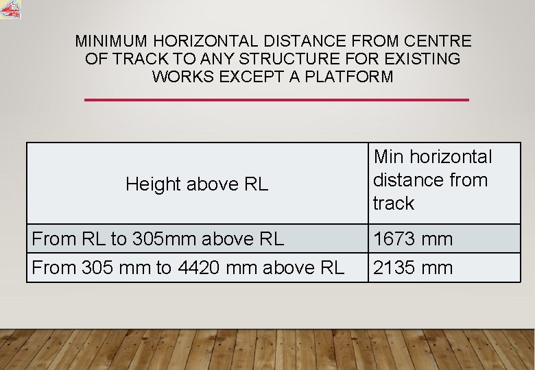
MINIMUM HORIZONTAL DISTANCE FROM CENTRE OF TRACK TO ANY STRUCTURE FOR EXISTING WORKS EXCEPT A PLATFORM Height above RL Min horizontal distance from track From RL to 305 mm above RL 1673 mm From 305 mm to 4420 mm above RL 2135 mm

MINIMUM HORIZONTAL DISTANCE FROM CENTRE OF TRACK TO ANY STRUCTURE FOR NEW WORKS/ALTERATIONS TO EXISTING WORKS Height above RL Horizontal distance from centre of track From RL to 305 mm above RL 1905 mm From 305 mm to 1065 mm above RL 1905 increasing to 2360 mm From 1065 mm to 3355 mm above RL 2360 mm From 3355 mm to 4420 mm above RL 2360 decreasing to 2135 mm From 4420 mm to 5870 mm above RL 2135 decreasing to 915 mm
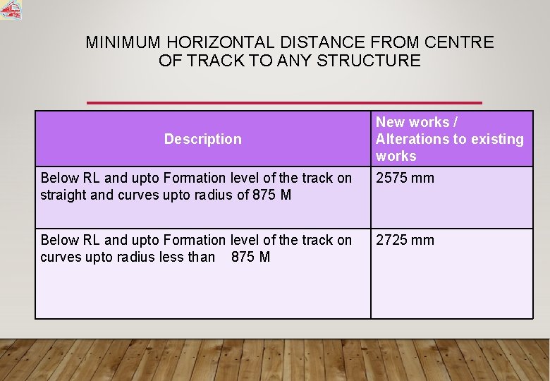
MINIMUM HORIZONTAL DISTANCE FROM CENTRE OF TRACK TO ANY STRUCTURE Description New works / Alterations to existing works Below RL and upto Formation level of the track on straight and curves upto radius of 875 M 2575 mm Below RL and upto Formation level of the track on curves upto radius less than 875 M 2725 mm
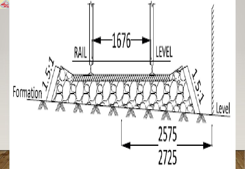
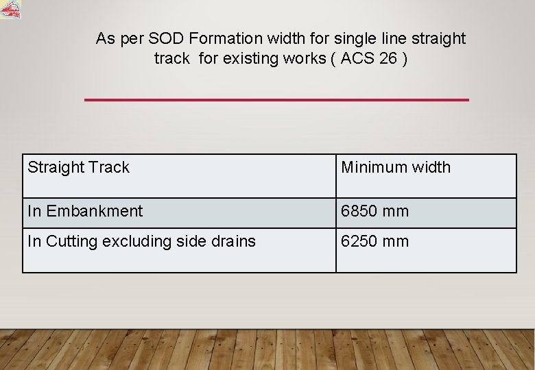
As per SOD Formation width for single line straight track for existing works ( ACS 26 ) Straight Track Minimum width In Embankment 6850 mm In Cutting excluding side drains 6250 mm

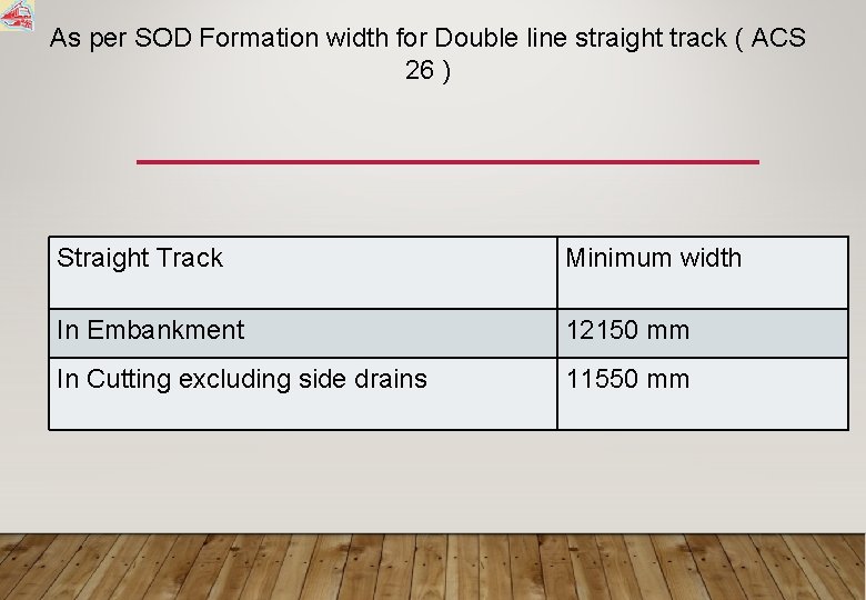
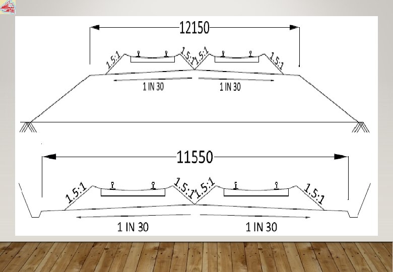
As per SOD Formation width for Double line straight track ( ACS 26 ) Straight Track Minimum width In Embankment 12150 mm In Cutting excluding side drains 11550 mm
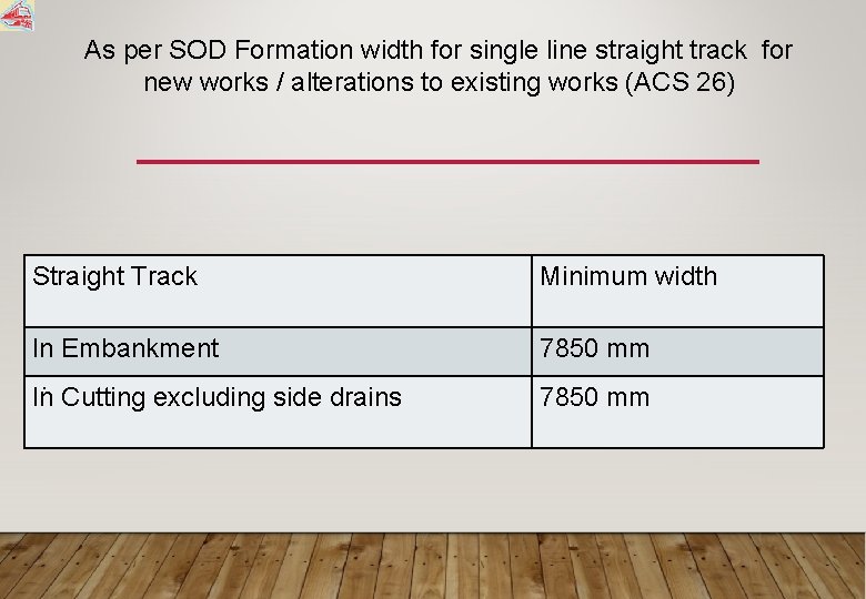
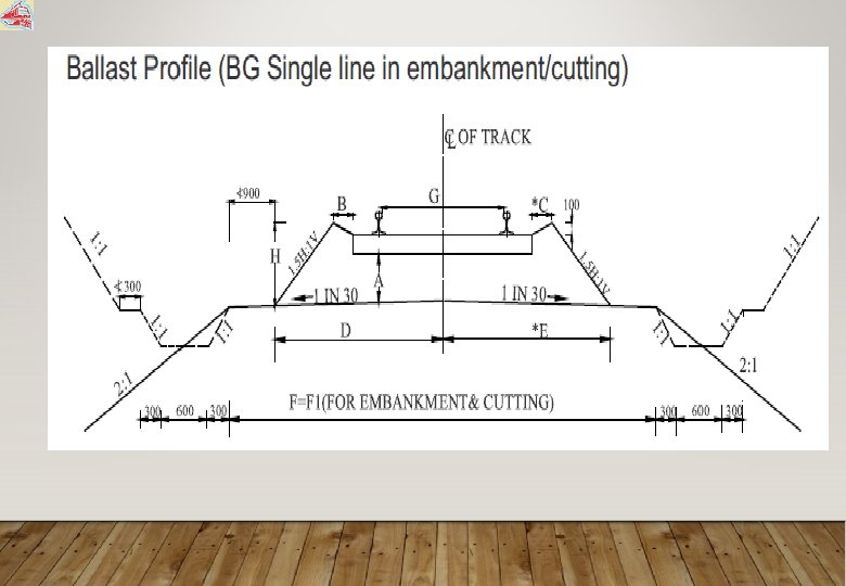
As per SOD Formation width for single line straight track for new works / alterations to existing works (ACS 26) Straight Track Minimum width In Embankment. In Cutting excluding side drains 7850 mm
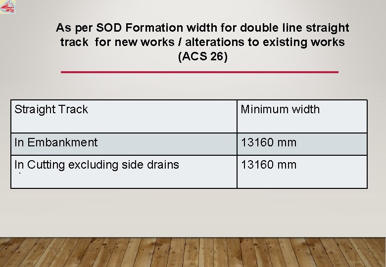
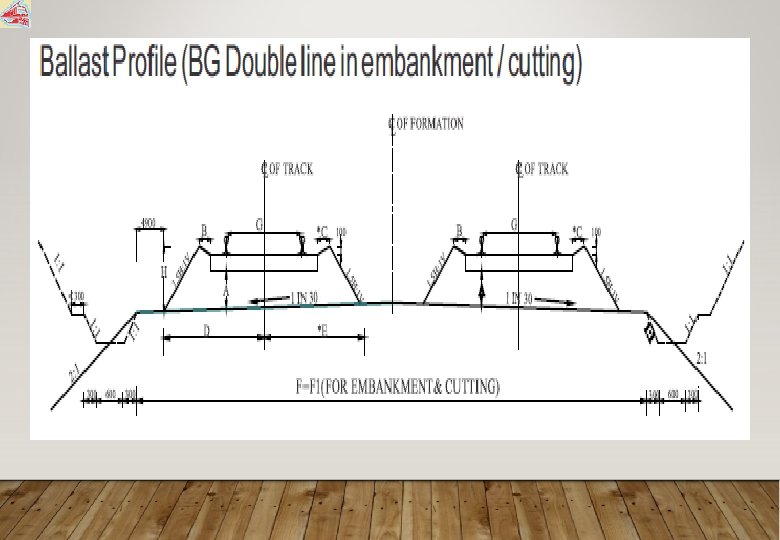
As per SOD Formation width for double line straight track for new works / alterations to existing works (ACS 26) Straight Track Minimum width In Embankment 13160 mm In Cutting excluding side drains. 13160 mm

LOADING GAUGE • A loading gauge defines the maximum height and width for railway vehicles and their loads to ensure that they can pass safely through tunnels and under bridges, and keep clear of trackside buildings and structures.
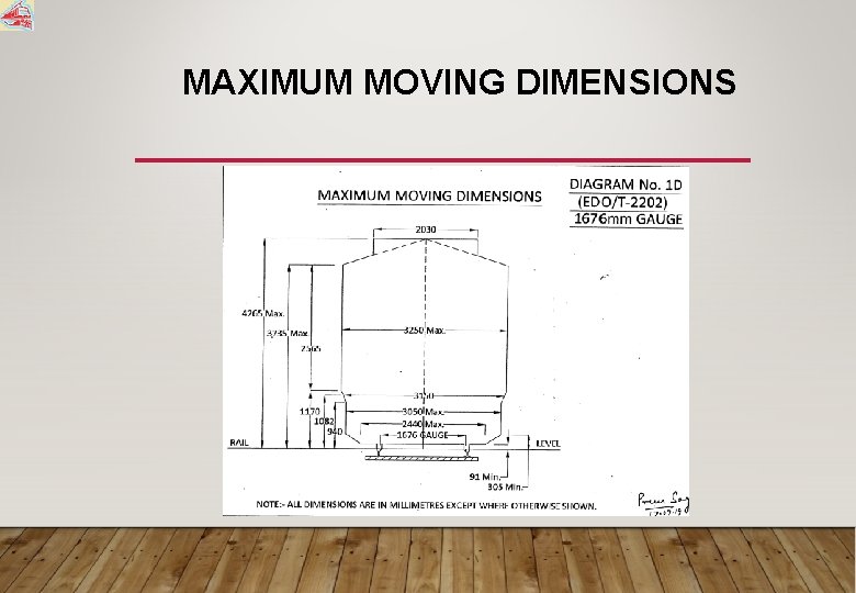
MAXIMUM MOVING DIMENSIONS

OVER DIMENSIONAL CONSIGNMENTS (ODC) An ODC is found which, when loaded is on the ordinary open wagon, would infringe the maximum moving dimension of the gauge over which is to be moved. The infringement includes infringement to OHE, ROB etc and for such consignment special permission and precautions are to be taken, including imposition of SR or permitting in routes where it is not going to endanger hitting any existing structure.

TRACK MACHINES • Function of Machines • Maintenance Of track • Laying and Renewal of Track • Types of Machines • On Track Machines (Heavy Track Machines) • Off Track Machines (Small Track Machines)
WHAT IS TO BE MAINTAINED § MAINTENCE OF TRACK COMPONENTS • RAIL • SLEEPERS • FITTINGS • BALLAST • FORMATION § MAINTENACE OF TRACK PARAMETERS • CROSS LEVEL • ALIGNMENT • UNEVENNESS • GAUGE

WHY MAINTENANCE • Track Components and Track parameters detoriate with time (Dynamic impact). • Track parameters requires restoration and track components may require replacement for safety of Train and for improving riding comfort. • Track Parameters if not restored increases rate of detoriation of track components.
WHY MAINTENANCE CONTD. . Maintenance is done to either • Replace the worn out components. • Take corrective action to increase the life of components where ever possible. • Maintain track parameters within limits specified for safety & riding comfort.
WHY MECHANISED MAINTENANCE • Ever increasing traffic and axle load • Modern and heavy track structure • Availability of time for maintenance is reducing • Quality of output is much better & superior • Economical

MAINTENANCE SCHEDULE (SCHEDULED MAINTENANCE ACTIVITY) • Maintaining Track Parameters (Tamping machines): CTE of railway to decide on frequency but normally earlier than a year. • Restoring Ballast quality (Deep Screening by) : Every 10 year or 500 GMT • Improving Rail Life (Rail Grinding ): After 25 GMT and then after every 50 GMT
MAINTENANCE SCHEDULE (RENEWAL ACTIVITY) Replacement of track components: • Rail: Life 800 GMT (TRR) • Sleeper: life 35 Years (TSR) • Rail and sleeper: CTR • Renewal of Fittings (GMT & years)(Manual) • Weld Renewal (TWR) • Through Bridge sleeper renewal (TBR)
MAINTENANCE SCHEDULE CONTD. . Other regular Maintenance activities (No schedule): • Shoulder Ballast overhauling. • Ballast regulating to get LWR Profile. • Casual Renewal of Rail and Sleepers etc
TAMPING MACHINES-PLAIN TRACK For track geometry correction (? ) Now CTE to decide Earlier-Once in two year or 100 GMT whichever is earlier.
TAMPING MACHINES • Plain Track tampers (For Work site) • Duomatic • Plain Track Tampers (For Maintenance) • CSM • T-Exp • Points and Crossing tampers • Unimat 2 s, 3 s, 4 s
BALLAST HANDLING MACHINES • BALLAST CLEANING MACHINE- BCM • SHOULDER BALLAST CLEANING MACHINE-SBCM • BALLAST REGULATING MACHINES-BRM
Rail maintenance machines Rail Grinding Machine (RGM)

TRACK LAYING MACHINES • TRACK LAYING EQUIPMENT (TLE) • TRACK LAYING TRAIN (TRT) • POINTS AND CROSSING LAYING MACHINE -T 28
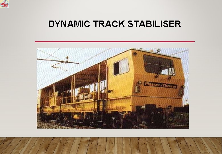
DYNAMIC TRACK STABILISER

MATERIAL HANDLING MACHINE • Rail Borne Maintenance Vehicle (RBMV) • Utility Vehicle (UTV)

FUTURE MACHINES • MUCK DISPOSAL UNIT. • HIGH OUTPUT BCM (Capacity 900 cum) • FORMATION REHABILITATION MACHINE. • MOBILE FLASH BUTT WELDING PLANT. • SWITCH GRINDING MACHINE • MILLING MACHINE

- Slides: 75