
TOWARDS 3 D GAMMA RAY IMAGING Enzo PARADISO



- Slides: 30
TOWARDS 3 D GAMMA -RAY IMAGING Enzo PARADISO EDUSAFE Final Review 20 June 2016
• • Gamma camera prototype recap Panoramic gamma Imaging Gamma sensor calibration 3 -D Gamma imaging Overview - 20 June 2016 – p. 2 Overview
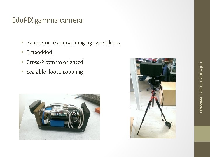
Edu. PIX gamma camera • Panoramic Gamma Imaging capabilities • Cross-Platform oriented • Scalable, loose coupling Overview - 20 June 2016 – p. 3 • Embedded
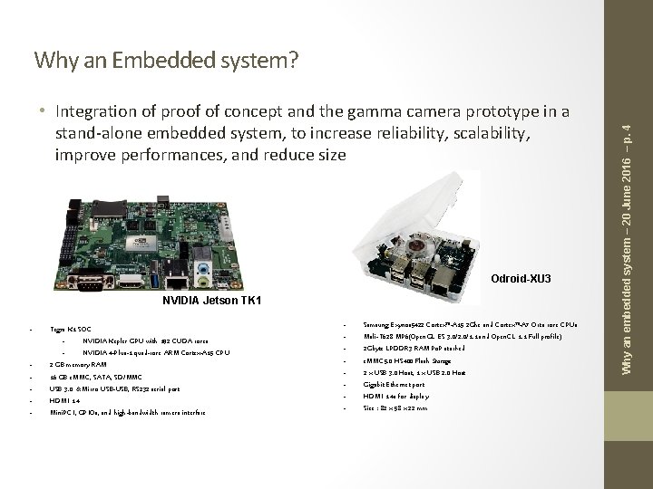
• Integration of proof of concept and the gamma camera prototype in a stand-alone embedded system, to increase reliability, scalability, improve performances, and reduce size Odroid-XU 3 NVIDIA Jetson TK 1 - Tegra K 1 SOC NVIDIA Kepler GPU with 192 CUDA cores NVIDIA 4 -Plus-1 quad-core ARM Cortex-A 15 CPU 2 GB memory RAM 16 GB e. MMC, SATA, SD/MMC USB 3. 0 & Micro USB-USB, RS 232 serial port HDMI 1. 4 Mini. PCI, GPIOs, and high-bandwidth camera interface - Samsung Exynos 5422 Cortex™-A 15 2 Ghz and Cortex™-A 7 Octa core CPUs Mali-T 628 MP 6(Open. GL ES 3. 0/2. 0/1. 1 and Open. CL 1. 1 Full profile) 2 Gbyte LPDDR 3 RAM Po. P stacked e. MMC 5. 0 HS 400 Flash Storage 2 x USB 3. 0 Host, 1 x USB 2. 0 Host Gigabit Ethernet port HDMI 1. 4 a for display Size : 82 x 58 x 22 mm Why an embedded system – 20 June 2016 – p. 4 Why an Embedded system?
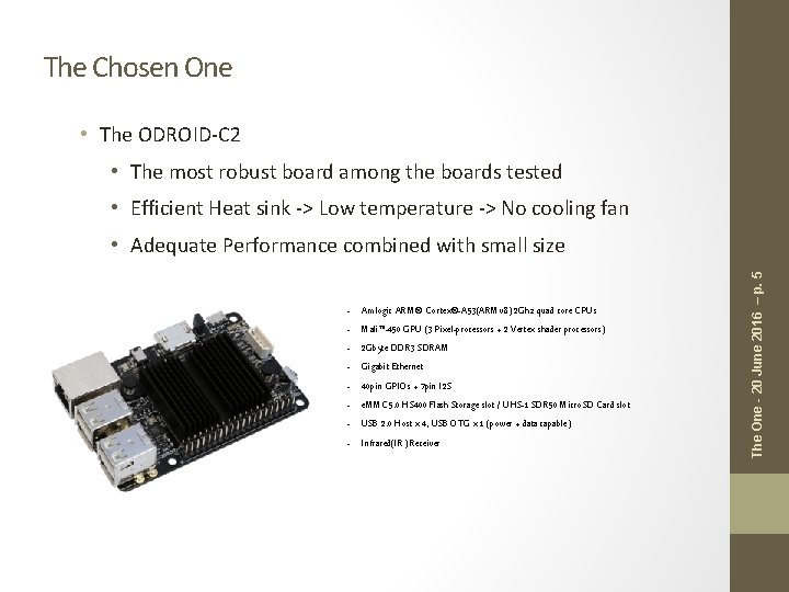
The Chosen One • The ODROID-C 2 • The most robust board among the boards tested • Efficient Heat sink -> Low temperature -> No cooling fan - Amlogic ARM® Cortex®-A 53(ARMv 8) 2 Ghz quad core CPUs Mali™-450 GPU (3 Pixel-processors + 2 Vertex shader processors) 2 Gbyte DDR 3 SDRAM Gigabit Ethernet 40 pin GPIOs + 7 pin I 2 S e. MMC 5. 0 HS 400 Flash Storage slot / UHS-1 SDR 50 Micro. SD Card slot USB 2. 0 Host x 4, USB OTG x 1 (power + data capable) Infrared(IR) Receiver The One - 20 June 2016 – p. 5 • Adequate Performance combined with small size
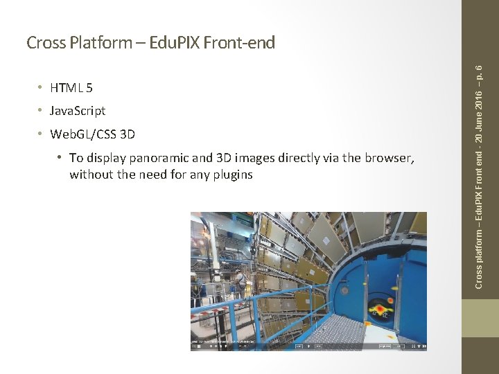
• HTML 5 • Java. Script • Web. GL/CSS 3 D • To display panoramic and 3 D images directly via the browser, without the need for any plugins Cross platform – Edu. PIX Front end - 20 June 2016 – p. 6 Cross Platform – Edu. PIX Front-end
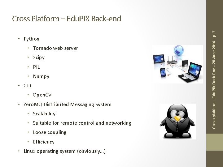
• Python • Tornado web server • Scipy • PIL • Numpy • C++ • Open. CV • Zero. MQ Distributed Messaging System • Scalability • Suitable for remote control and networking • Loose coupling • Efficiency • Linux operating system (obviously…) Cross platform – Edu. PIX Back End - 20 June 2016 – p. 7 Cross Platform – Edu. PIX Back-end
• • Gamma camera prototype recap Panoramic gamma Imaging Gamma sensor registration 3 -D Gamma imaging Outline - 20 June 2016 – p. 8 Outline
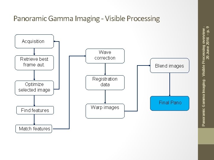
Acquisition Retrieve best frame aut. Optimize selected image Find features Match features Wave correction Blend images Registration data Warp images Final Panoramic Gamma Imaging - Visible Processing overview 20 June 2016 – p. 9 Panoramic Gamma Imaging - Visible Processing
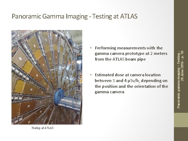
• Performing measurements with the gamma camera prototype at 2 meters from the ATLAS beam pipe • Estimated dose at camera location between 3 and 4 µSv/h, depending on the position and the orientation of the gamma camera Testing at ATLAS Panoramic gamma imaging – Testing 20 June 2016 – p. 10 Panoramic Gamma Imaging - Testing at ATLAS
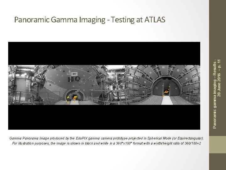
Panoramic gamma imaging – Results 20 June 2016 – p. 11 Panoramic Gamma Imaging - Testing at ATLAS Gamma Panorama Image produced by the Edu. PIX gamma camera prototype projected in Spherical Mode (or Equirectangular). For illustration purposes, the image is shown in black and white in a 360°x 180° format with a width/height ratio of 360/180=2
• • Gamma camera prototype recap Panoramic gamma Imaging Gamma sensor calibration 3 -D Gamma imaging Outline - 20 June 2016 – p. 12 Outline
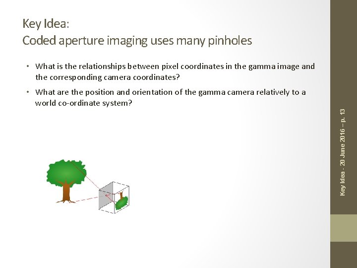
Key Idea: Coded aperture imaging uses many pinholes • What is the relationships between pixel coordinates in the gamma image and the corresponding camera coordinates? Key Idea - 20 June 2016 – p. 13 • What are the position and orientation of the gamma camera relatively to a world co-ordinate system?
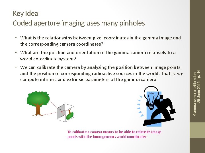
Key Idea: Coded aperture imaging uses many pinholes • What is the relationships between pixel coordinates in the gamma image and the corresponding camera coordinates? • We can calibrate the camera by analyzing the position between image points and the position of corresponding radioactive sources in the world. That is, we compute intrinsic and extrinsic parameters of the gamma camera To calibrate a camera means to be able to relate its image points with the homogeneous world coordinates Gamma camera calibration 20 June 2016 – p. 14 • What are the position and orientation of the gamma camera relatively to a world co-ordinate system?
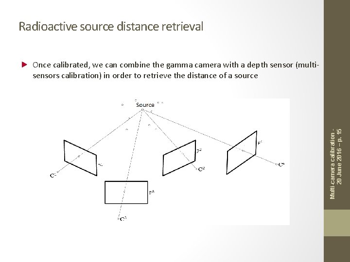
Radioactive source distance retrieval Multi-camera calibration 20 June 2016 – p. 15 Once calibrated, we can combine the gamma camera with a depth sensor (multisensors calibration) in order to retrieve the distance of a source
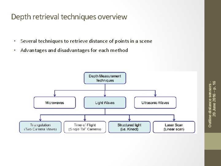
Depth retrieval techniques overview • Several techniques to retrieve distance of points in a scene Outline distance sensors 20 June 2016 – p. 16 • Advantages and disadvantages for each method
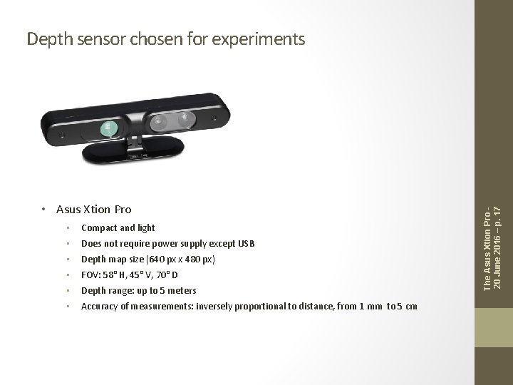
• Asus Xtion Pro • Compact and light • Does not require power supply except USB • Depth map size (640 px x 480 px) • FOV: 58° H, 45° V, 70° D • Depth range: up to 5 meters • Accuracy of measurements: inversely proportional to distance, from 1 mm to 5 cm The Asus Xtion Pro 20 June 2016 – p. 17 Depth sensor chosen for experiments
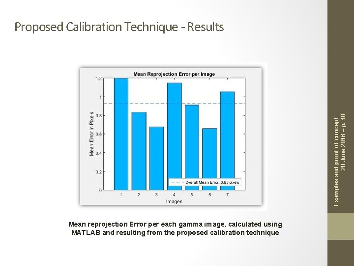
Examples and proof-of-concept 20 June 2016 – p. 18 Proposed Calibration Technique - Results Mean reprojection Error per each gamma image, calculated using MATLAB and resulting from the proposed calibration technique
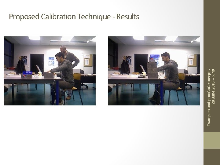
Examples and proof-of-concept 20 June 2016 – p. 19 Proposed Calibration Technique - Results
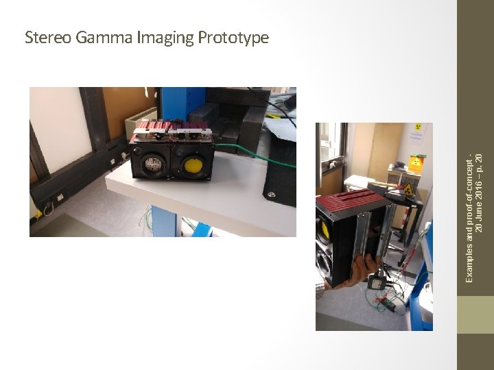
Examples and proof-of-concept 20 June 2016 – p. 20 Stereo Gamma Imaging Prototype
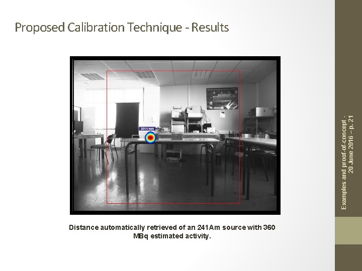
Examples and proof-of-concept 20 June 2016 – p. 21 Proposed Calibration Technique - Results Distance automatically retrieved of an 241 Am source with 360 MBq estimated activity.
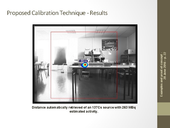
Examples and proof-of-concept 20 June 2016 – p. 22 Proposed Calibration Technique - Results Distance automatically retrieved of an 137 Cs source with 263 MBq estimated activity.
• • Gamma camera prototype recap Panoramic gamma Imaging Gamma sensor calibration 3 -D Gamma imaging Outline - 20 June 2016 – p. 23 Outline
Challenges • Embedded / power efficient • Rapid • Acceptable tolerance • Retrieve distance automatically • Compute 3 D position of radioactive sources • Design and development of appropriate software /hardware architecture solution for the prototype • 3 D gamma reconstruction: • Reconstruction of 3 D model of the physical scene • Tracking in a continuous manner the 6 Do. F pose of the sensor (location and orientation) • Volumetric integration of visible and gamma information Challenges – 20 June 2016 – p. 24 • Selection, testing and integration of appropriate methodology for data range estimation
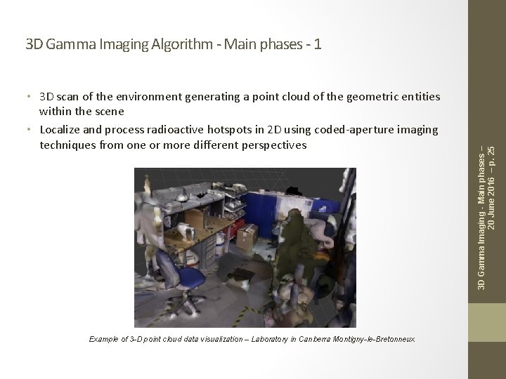
• 3 D scan of the environment generating a point cloud of the geometric entities within the scene • Localize and process radioactive hotspots in 2 D using coded-aperture imaging techniques from one or more different perspectives Example of 3 -D point cloud data visualization – Laboratory in Canberra Montigny-le-Bretonneux 3 D Gamma Imaging - Main phases – 20 June 2016 – p. 25 3 D Gamma Imaging Algorithm - Main phases - 1
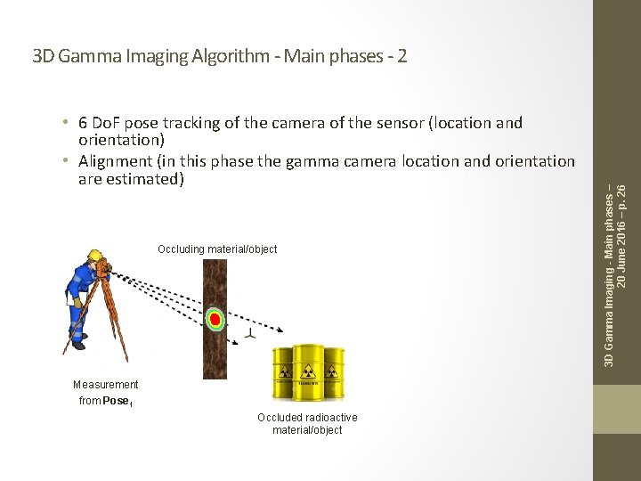
• 6 Do. F pose tracking of the camera of the sensor (location and orientation) • Alignment (in this phase the gamma camera location and orientation are estimated) Occluding material/object Measurement from Pose 1 Occluded radioactive material/object 3 D Gamma Imaging - Main phases – 20 June 2016 – p. 26 3 D Gamma Imaging Algorithm - Main phases - 2
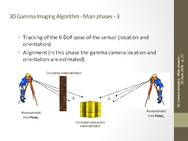
• Tracking of the 6 Do. F pose of the sensor (location and orientation) • Alignment (in this phase the gamma camera location and orientation are estimated) Occluding material/object Measurement from Pose 2 Measurement from Pose 1 Occluded radioactive material/object 3 D Gamma Imaging - Main phases – 20 June 2016 – p. 27 3 D Gamma Imaging Algorithm - Main phases - 3
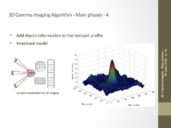
3 D Gamma Imaging Algorithm - Main phases - 4 • Add depth information to the hotspot profile Dynamic voxelization for 3 D imaging 3 D Gamma Imaging - Main phases – 20 June 2016 – p. 28 • Voxelized model
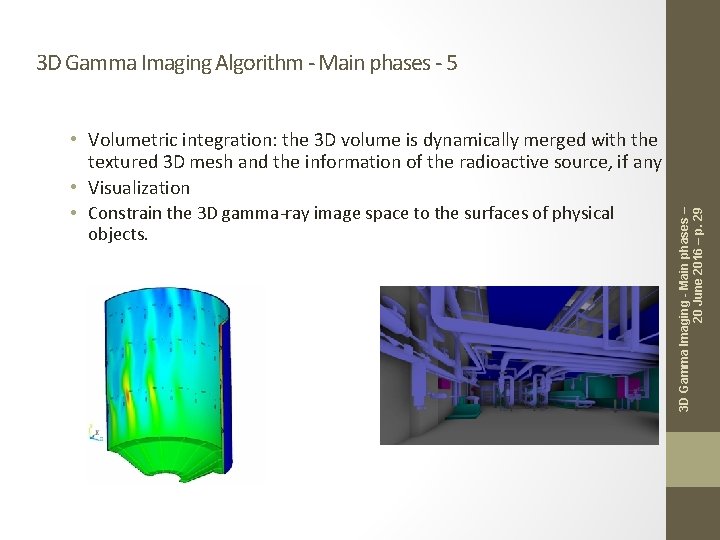
• Volumetric integration: the 3 D volume is dynamically merged with the textured 3 D mesh and the information of the radioactive source, if any • Visualization • Constrain the 3 D gamma-ray image space to the surfaces of physical objects. 3 D Gamma Imaging - Main phases – 20 June 2016 – p. 29 3 D Gamma Imaging Algorithm - Main phases - 5
Thank you!