
Total Harmonic Current Distortion THDI Harmonic 1 5












- Slides: 191
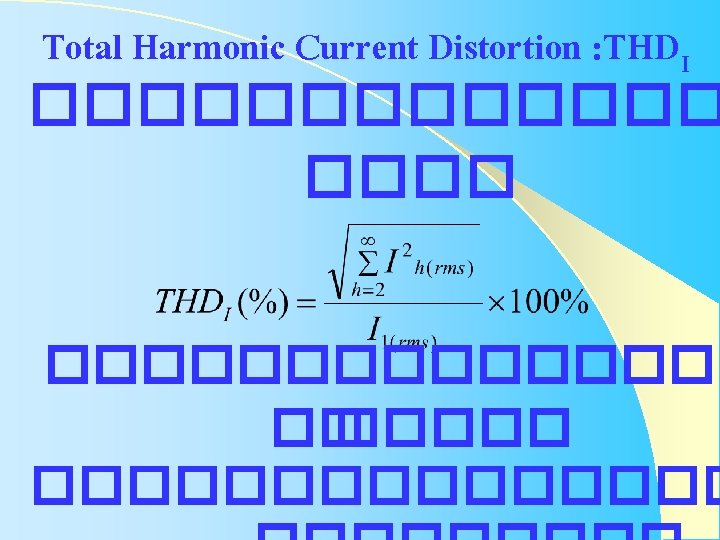
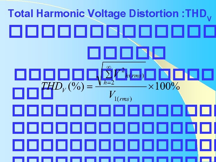
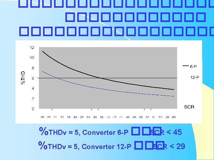
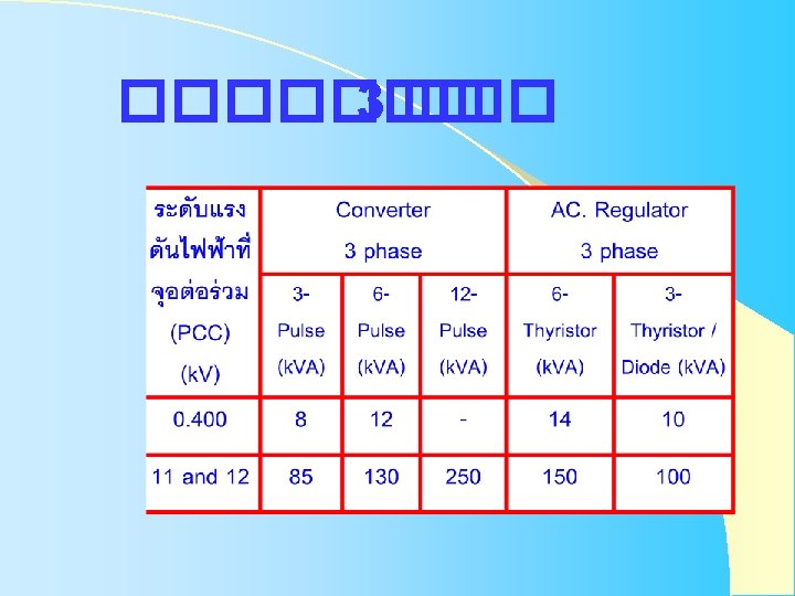
Total Harmonic Current Distortion : THDI ��������� �� ���������
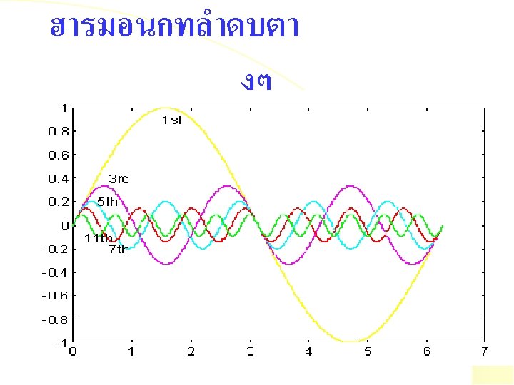
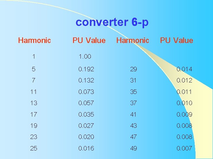
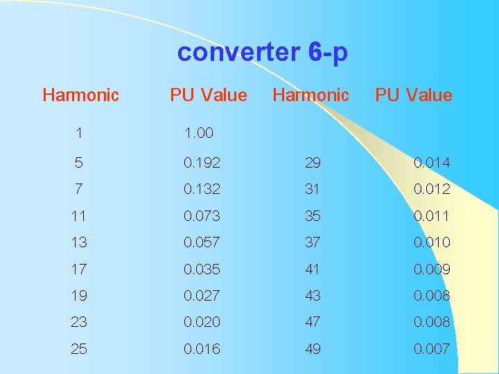
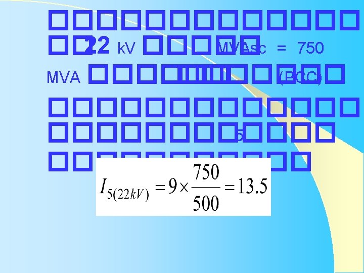
Harmonic 1 5 7 11 13 17 19 23 25 converter 6 -p PU Value Harmonic PU Value 1. 00 0. 192 0. 132 0. 073 0. 057 0. 035 0. 027 0. 020 0. 016 29 31 35 37 41 43 47 49 0. 014 0. 012 0. 011 0. 010 0. 009 0. 008 0. 007
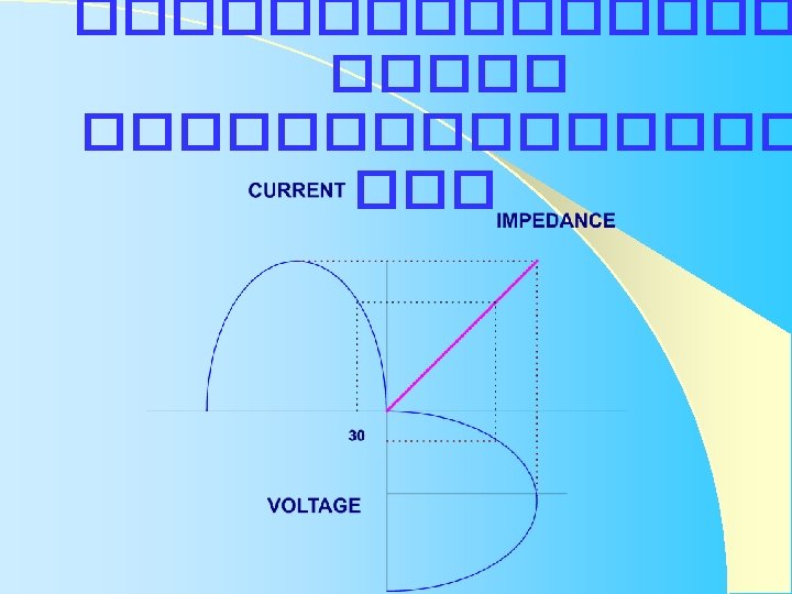
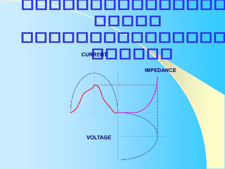
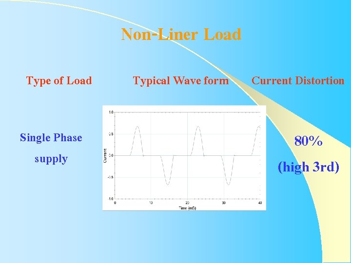
Non-Liner Load Type of Load Single Phase supply Typical Wave form Current Distortion 80% (high 3 rd)
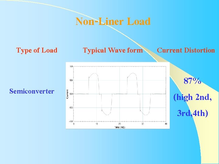
Non-Liner Load Type of Load Semiconverter Typical Wave form Current Distortion 87% (high 2 nd, 3 rd, 4 th)
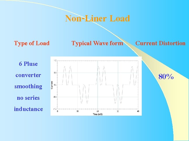
Non-Liner Load Type of Load 6 Pluse converter smoothing no series inductance Typical Wave form Current Distortion 80%
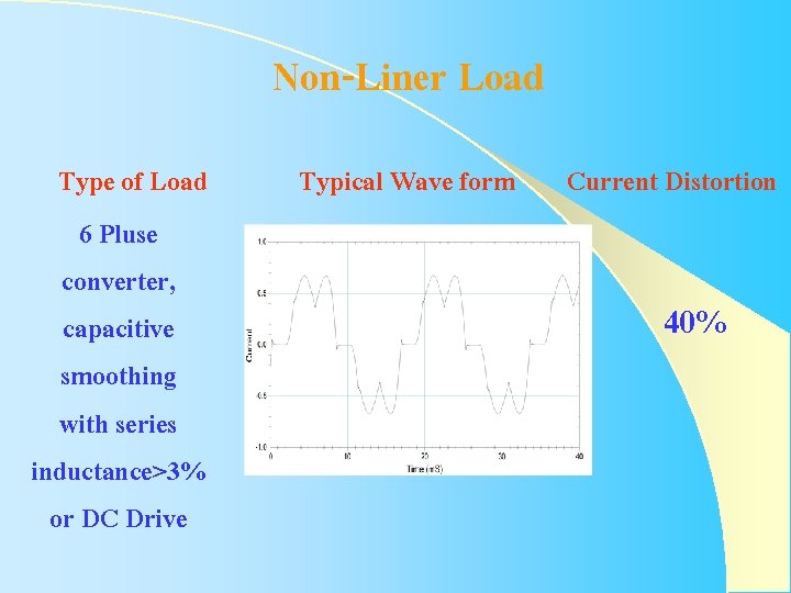
Non-Liner Load Type of Load 6 Pluse converter, capacitive smoothing with series inductance>3% or DC Drive Typical Wave form Current Distortion 40%
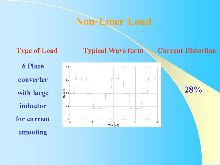
Non-Liner Load Type of Load 6 Pluse converter with large inductor for current smooting Typical Wave form Current Distortion 28%
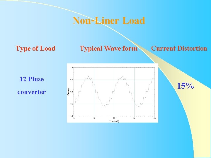
Non-Liner Load Type of Load 12 Pluse converter Typical Wave form Current Distortion 15%
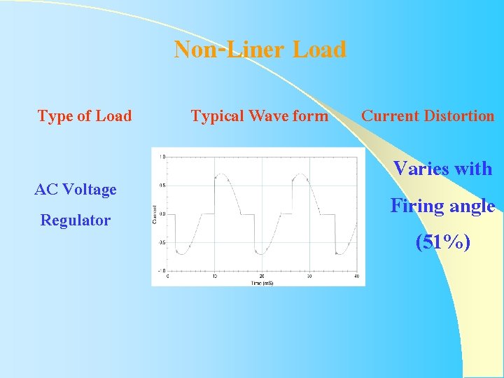
Non-Liner Load Type of Load AC Voltage Regulator Typical Wave form Current Distortion Varies with Firing angle (51%)
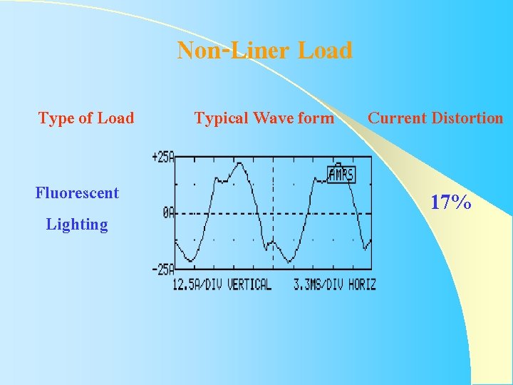
Non-Liner Load Type of Load Fluorescent Lighting Typical Wave form Current Distortion 17%
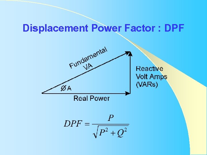
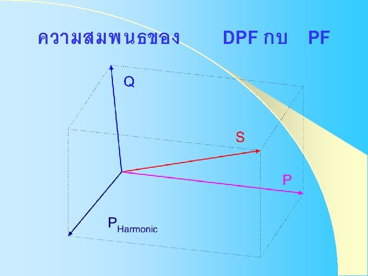
Displacement Power Factor : DPF
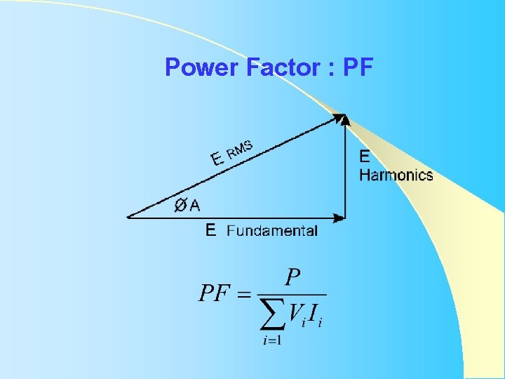
Power Factor : PF
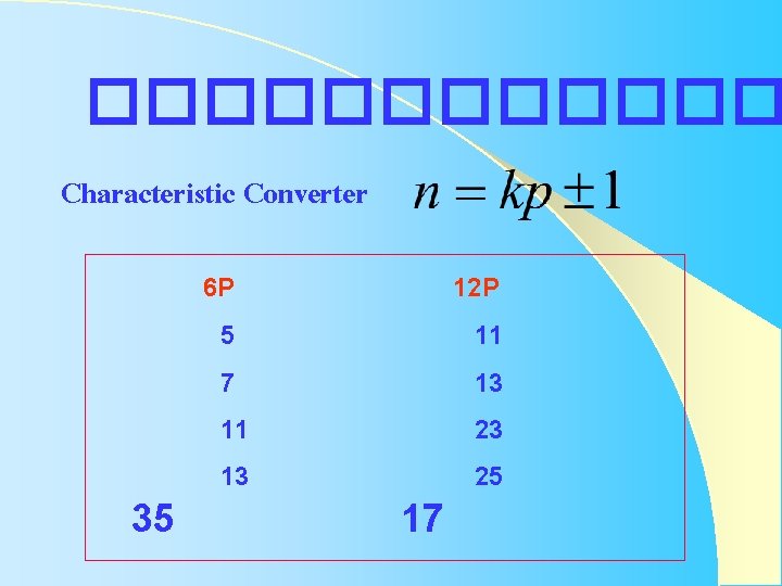
������ Characteristic Converter 35 6 P 5 7 11 13 17 12 P 11 13 23 25
Harmonic 1 5 7 11 13 17 19 23 25 converter 6 -p PU Value Harmonic PU Value 1. 00 0. 192 0. 132 0. 073 0. 057 0. 035 0. 027 0. 020 0. 016 29 31 35 37 41 43 47 49 0. 014 0. 012 0. 011 0. 010 0. 009 0. 008 0. 007
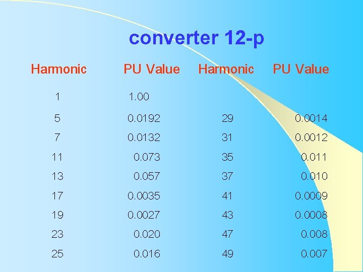
Harmonic 1 5 7 11 13 17 19 23 25 converter 12 -p PU Value Harmonic PU Value 1. 00 0. 0192 0. 0132 0. 073 0. 057 0. 0035 0. 0027 0. 020 0. 016 29 31 35 37 41 43 47 49 0. 0014 0. 0012 0. 011 0. 010 0. 0009 0. 0008 0. 007
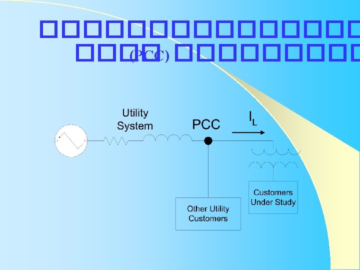
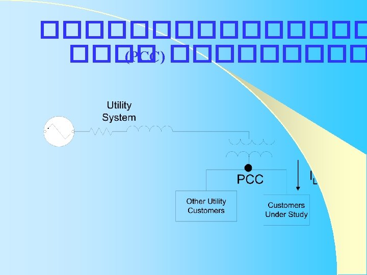
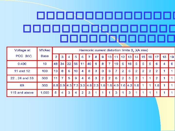
Point of Common Coupling : PCC��������� �����
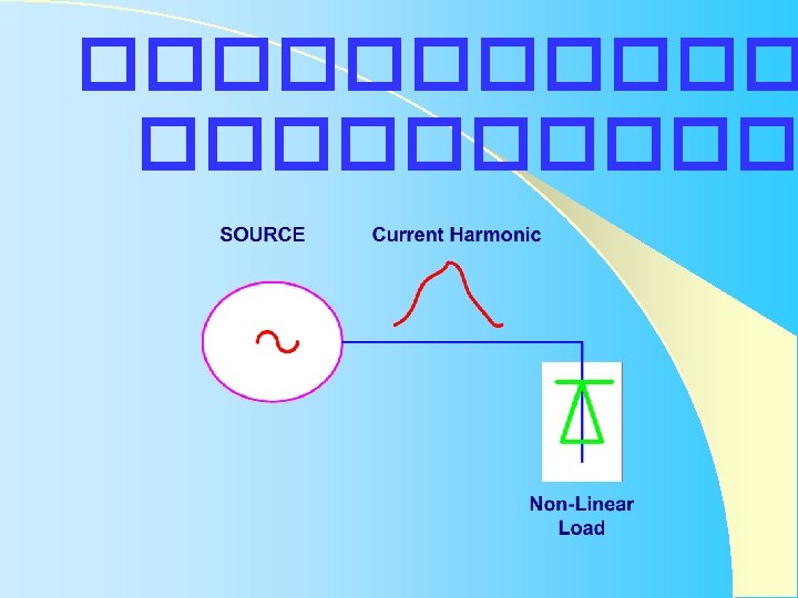
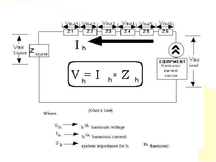
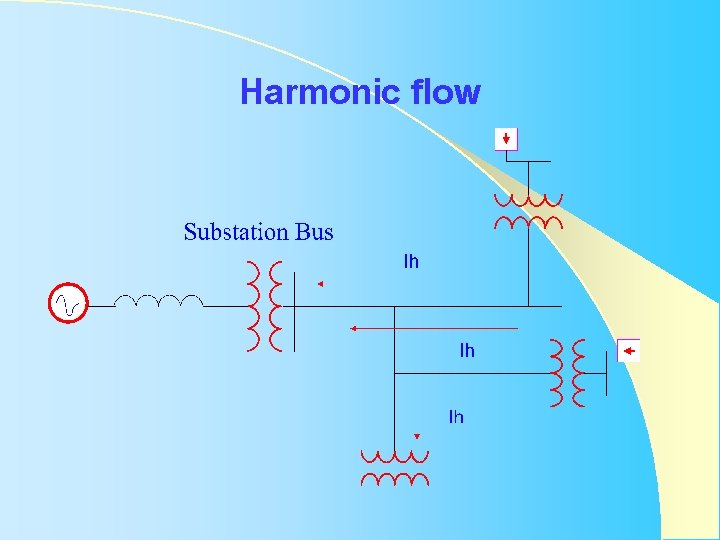
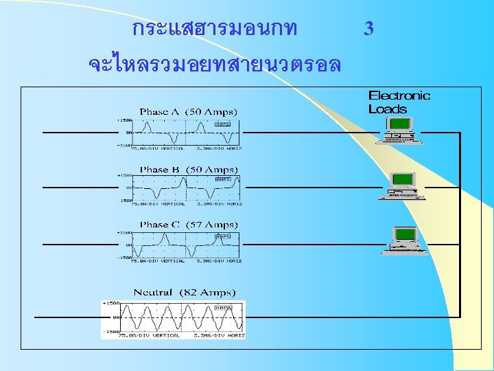
Harmonic flow
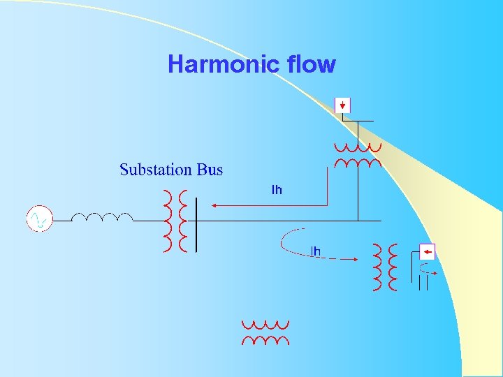
Harmonic flow
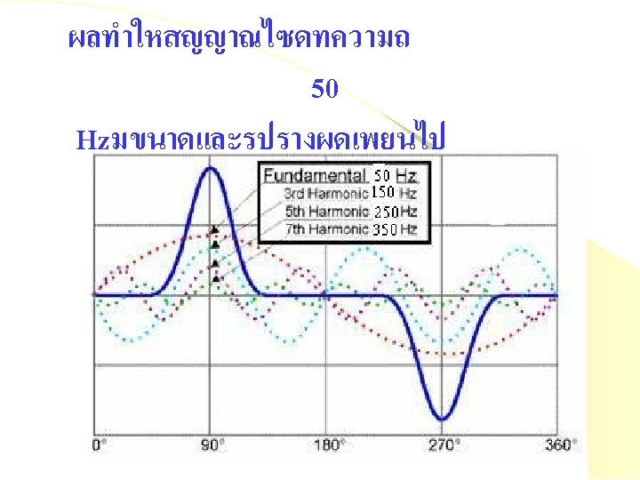
Source of Harmonic l l Electronic equipment Power electronic Arcing devices Saturable devices overexcited
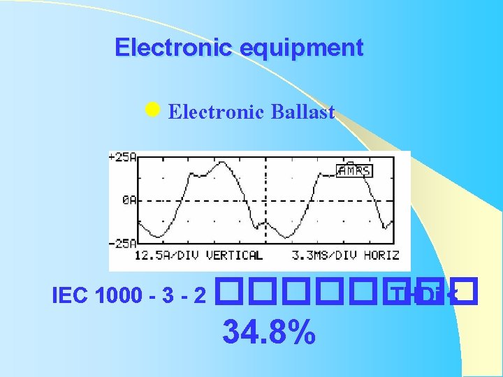
Electronic equipment l Electronic Ballast IEC 1000 - 3 - 2 ���� THDi < 34. 8%
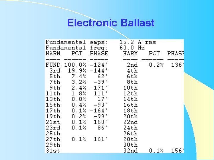
Electronic Ballast
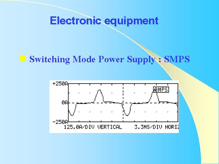
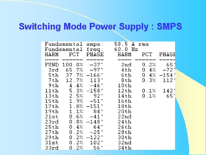
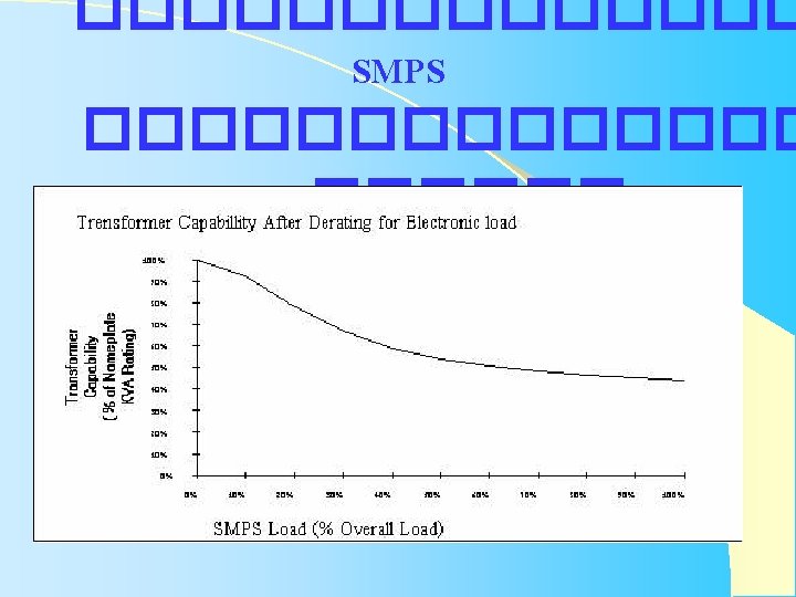
Electronic equipment l Switching Mode Power Supply : SMPS
Switching Mode Power Supply : SMPS
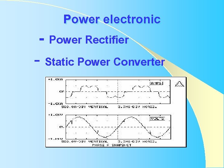
Power electronic - Power Rectifier - Static Power Converter
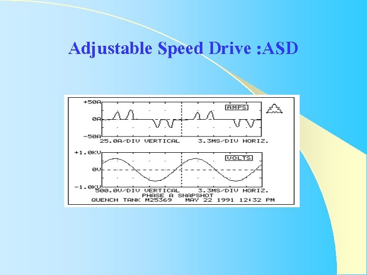
Adjustable Speed Drive : ASD
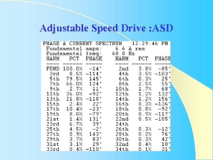
Adjustable Speed Drive : ASD
Arcing devices Induction Furnace l Arc Welding / Spot Welding l Arc Furnace l
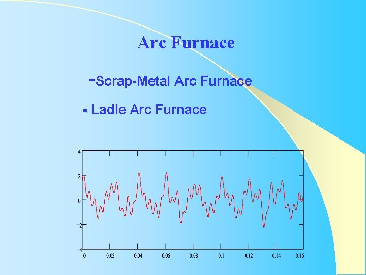
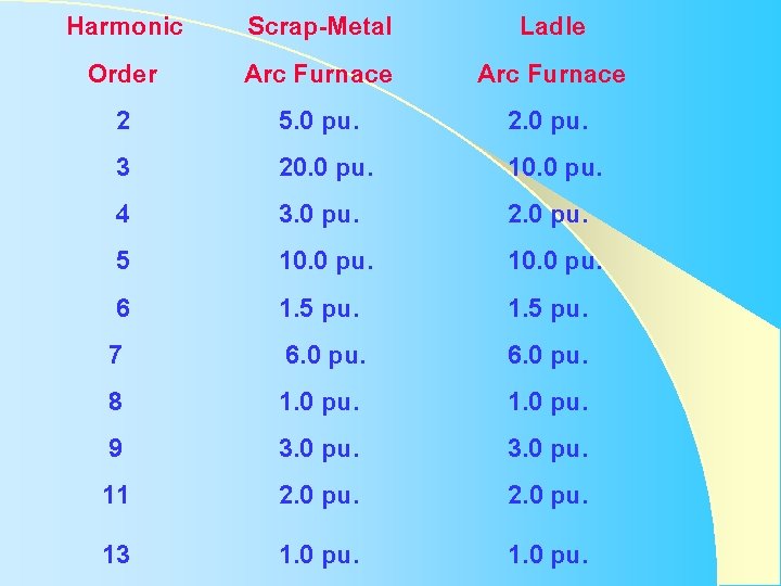
Arc Furnace -Scrap-Metal Arc Furnace - Ladle Arc Furnace
Harmonic Order 2 3 4 5 6 7 8 9 11 Scrap-Metal Arc Furnace 5. 0 pu. 20. 0 pu. 3. 0 pu. 10. 0 pu. 1. 5 pu. 6. 0 pu. 1. 0 pu. 3. 0 pu. 2. 0 pu. Ladle Arc Furnace 2. 0 pu. 10. 0 pu. 1. 5 pu. 6. 0 pu. 1. 0 pu. 3. 0 pu. 2. 0 pu. 13 1. 0 pu.
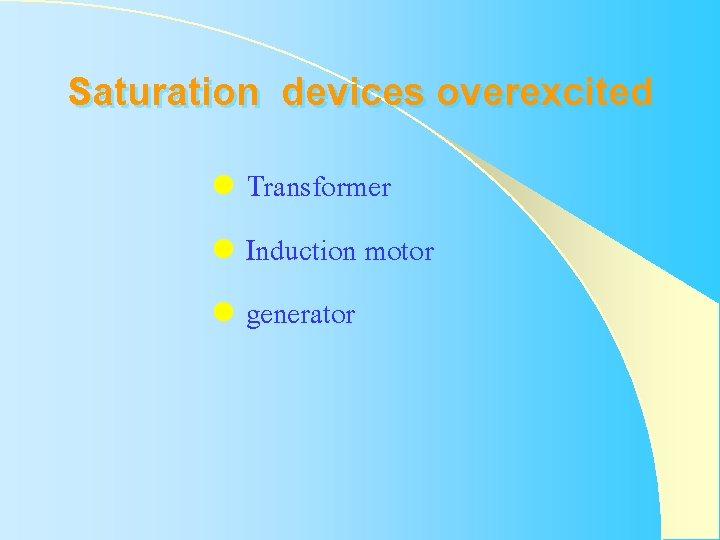
Saturation devices overexcited l Transformer l Induction motor l generator
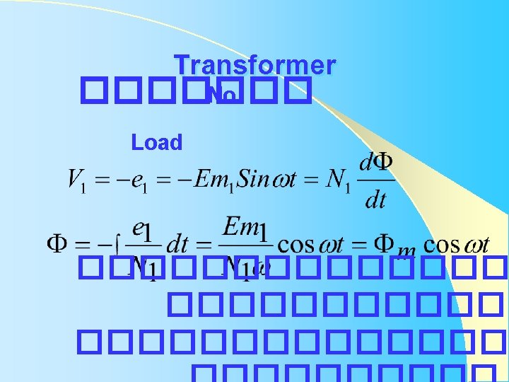
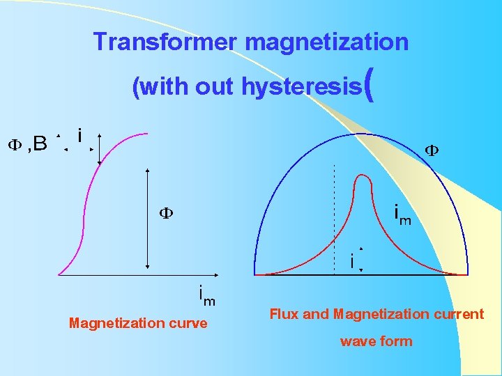
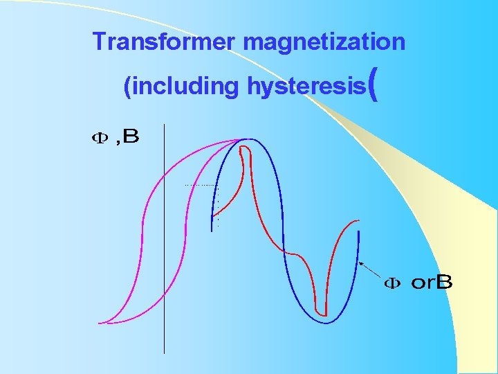
Transformer magnetization (with out hysteresis( Magnetization curve Flux and Magnetization current wave form
Transformer magnetization (including hysteresis(
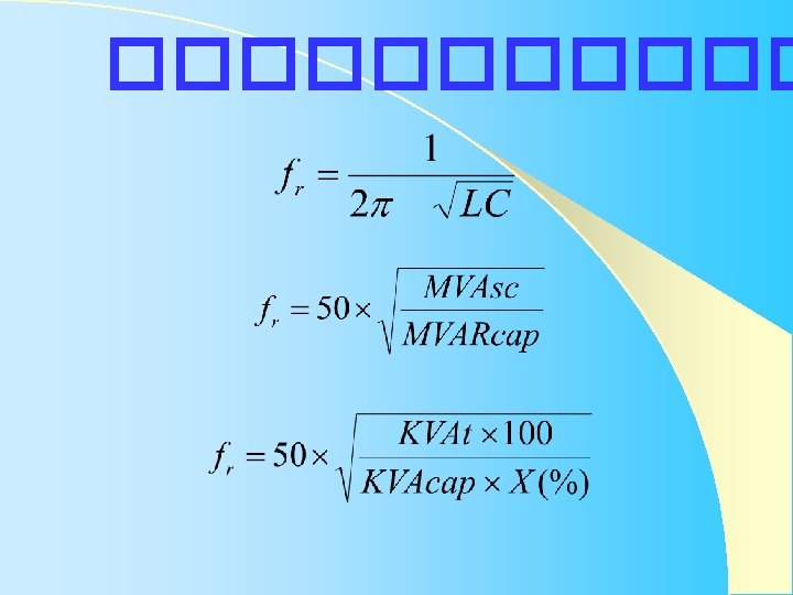
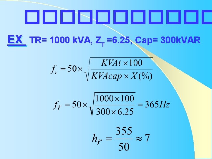
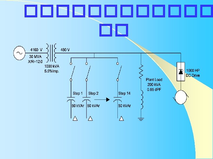
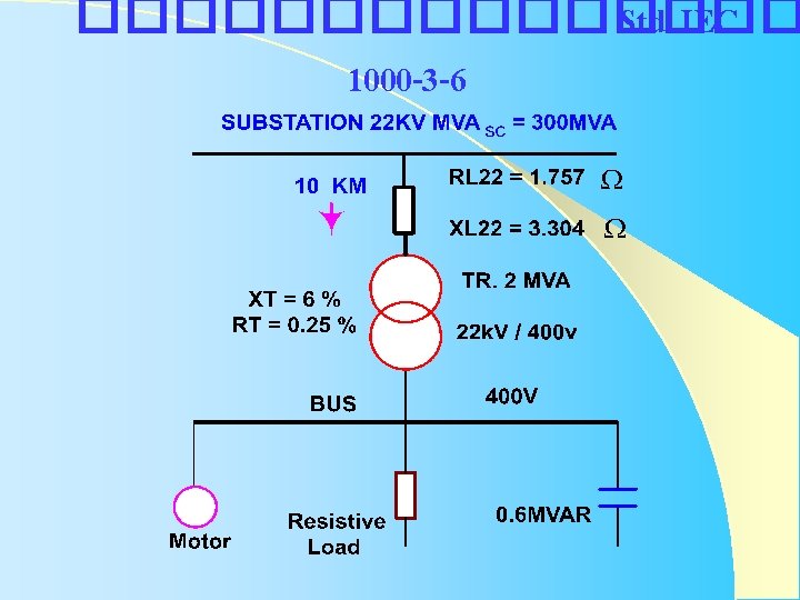
������ EX TR= 1000 k. VA, ZT =6. 25, Cap= 300 k. VAR
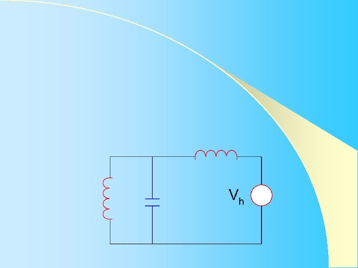
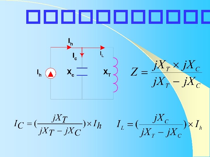
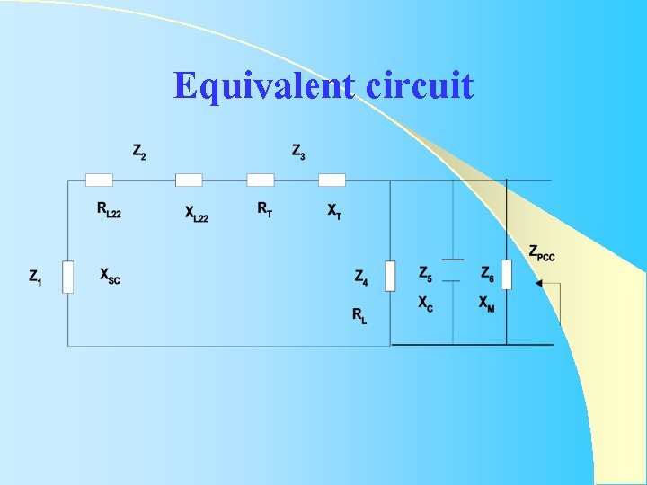
Equivalent circuit
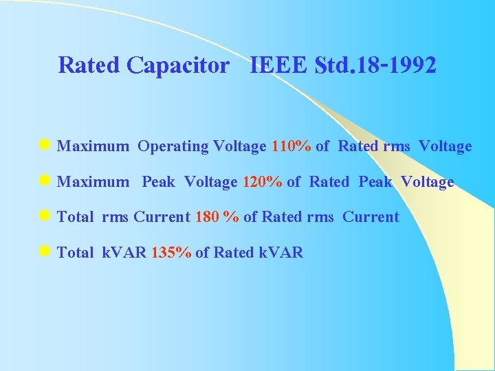
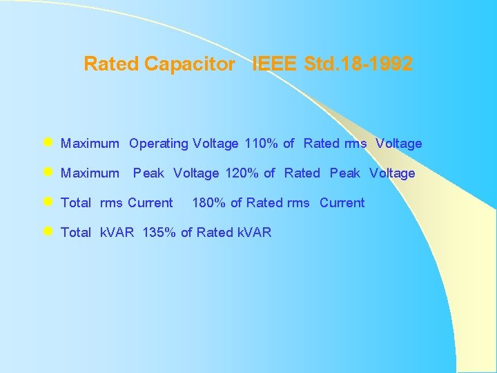
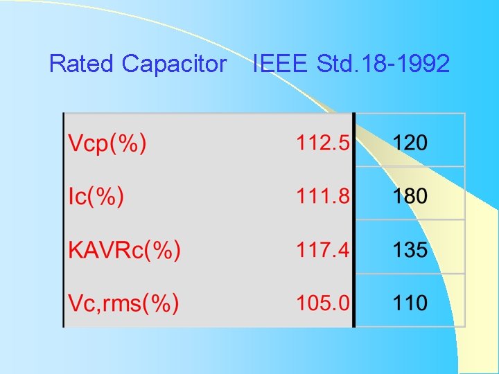
Rated Capacitor IEEE Std. 18 -1992 l Maximum Operating Voltage 110% of Rated rms Voltage l Maximum Peak Voltage 120% of Rated Peak Voltage l Total rms Current 180 % of Rated rms Current l Total k. VAR 135% of Rated k. VAR
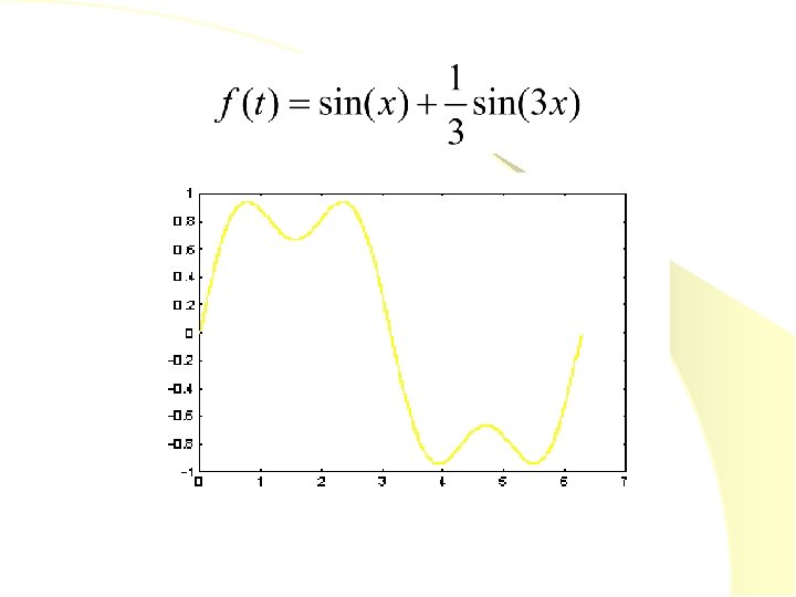
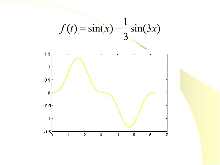
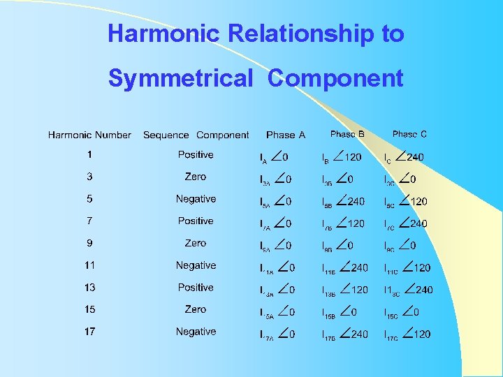
Harmonic Relationship to Symmetrical Component
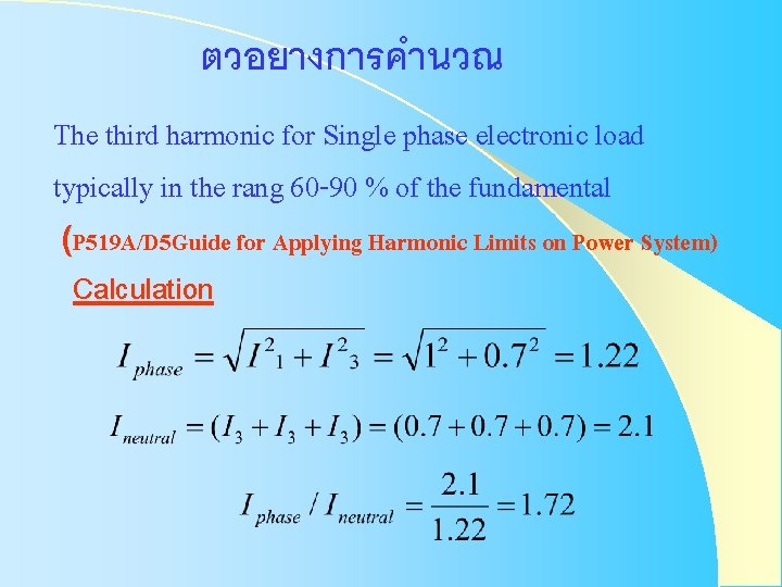
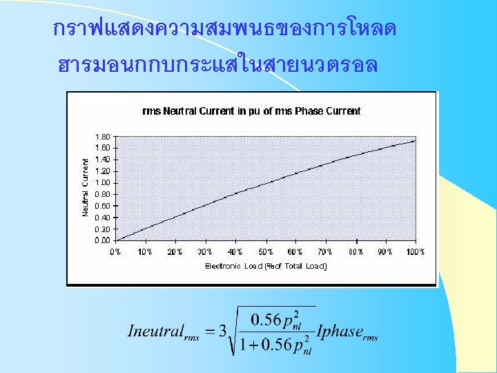
ตวอยางการคำนวณ The third harmonic for Single phase electronic load typically in the rang 60 -90 % of the fundamental (P 519 A/D 5 Guide for Applying Harmonic Limits on Power System) Calculation
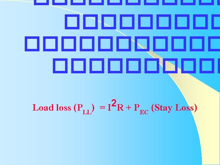
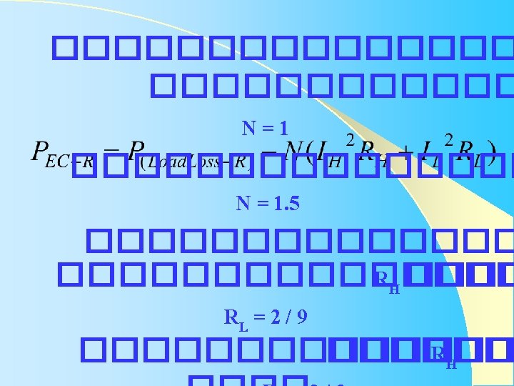
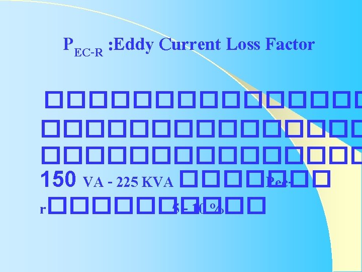
����������� Load loss (PLL) 2 =I R+P EC (Stay Loss)
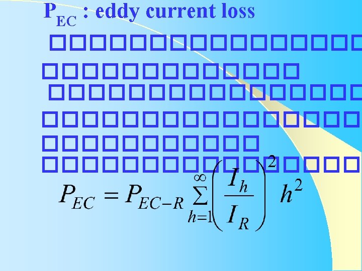
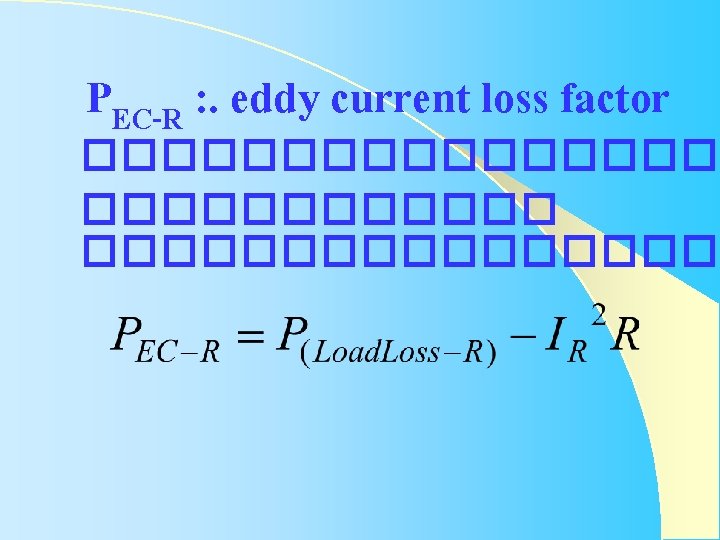
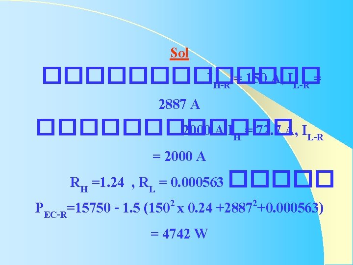
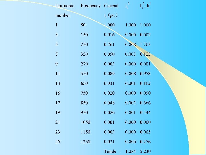
Sol ������� IH-R = 150 A, IL-R = 2887 A ������ 2000 A IH = 72. 7 A, IL-R = 2000 A RH =1. 24 , RL = 0. 000563 ����� PEC-R=15750 - 1. 5 (1502 x 0. 24 +28872+0. 000563) = 4742 W
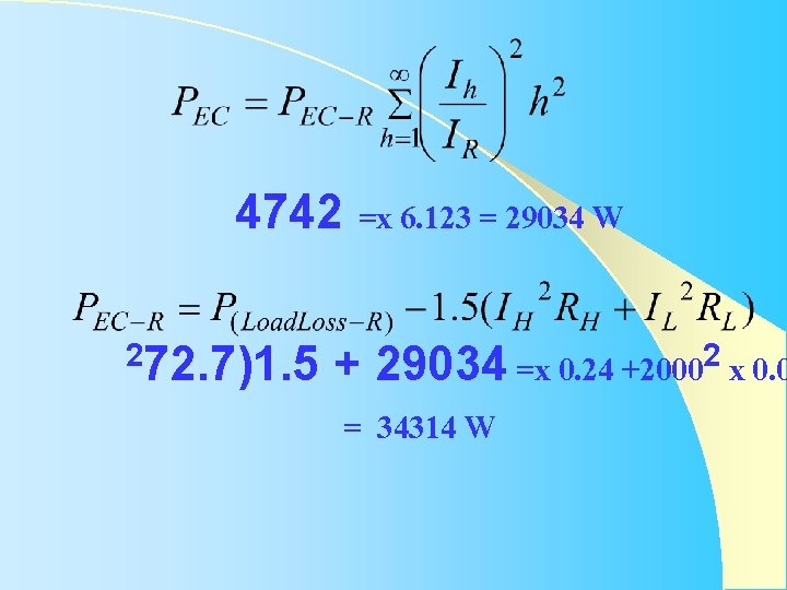
4742 =x 6. 123 = 29034 W 272. 7)1. 5 2 29034 =x 0. 24 +2000 x 0. 0 + = 34314 W
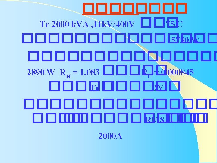
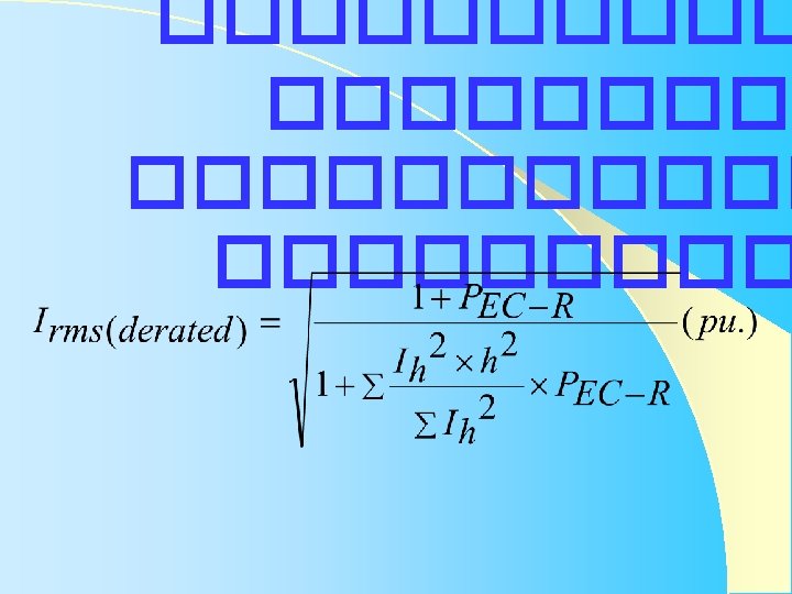
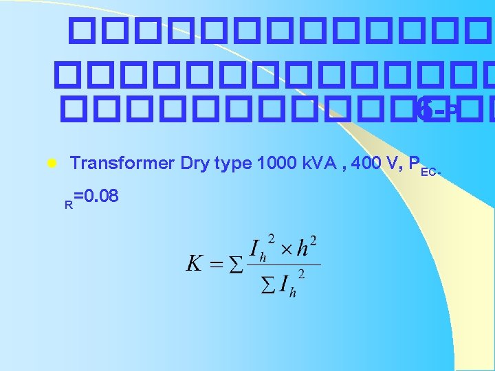
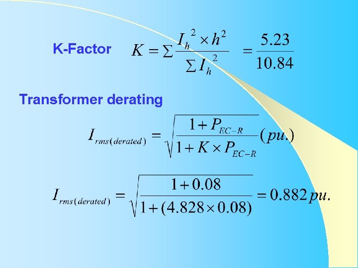
�������������� 6 -P l Transformer Dry type 1000 k. VA , 400 V, PECR=0. 08
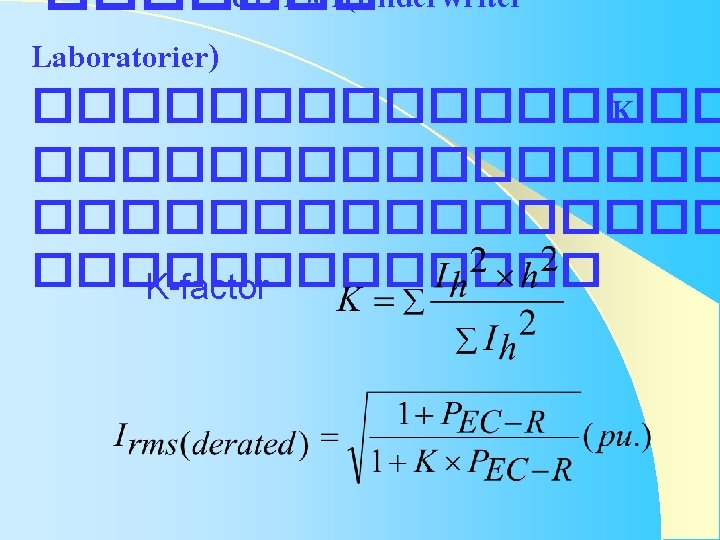
K-Factor Transformer derating
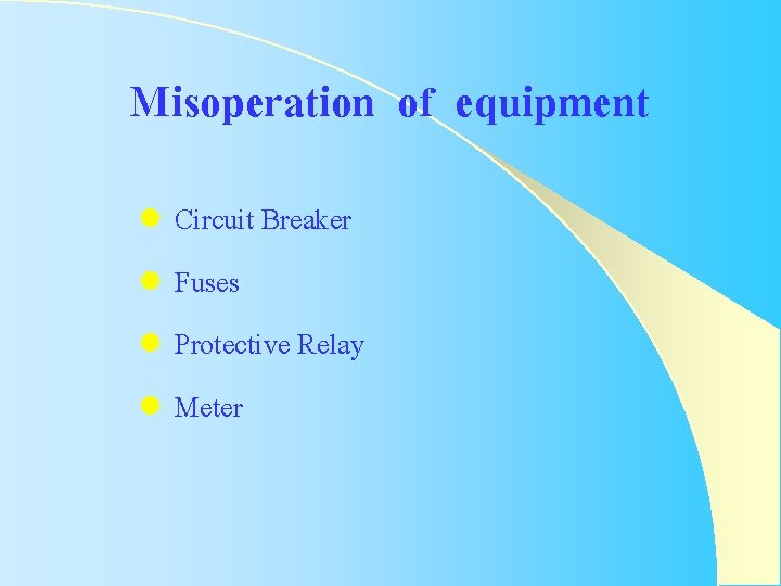
Misoperation of equipment Circuit Breaker l Fuses l Protective Relay l Meter l
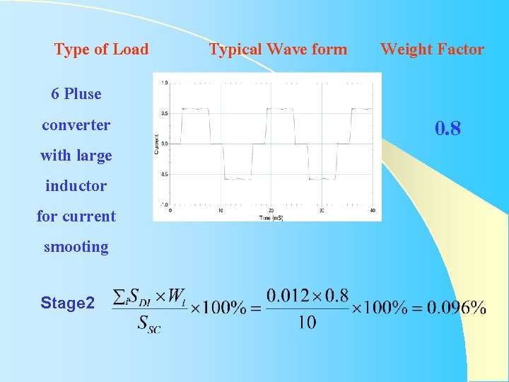
Type of Load 6 Pluse converter with large inductor for current smooting Stage 2 Typical Wave form Weight Factor 0. 8
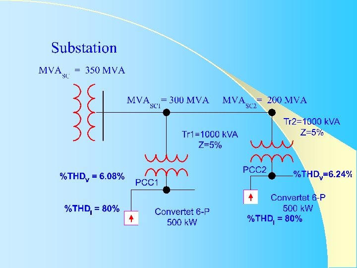
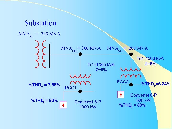
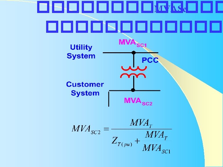
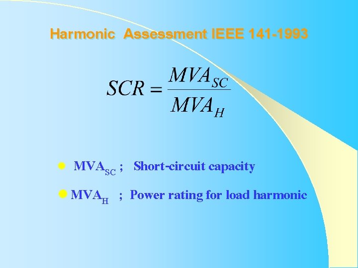
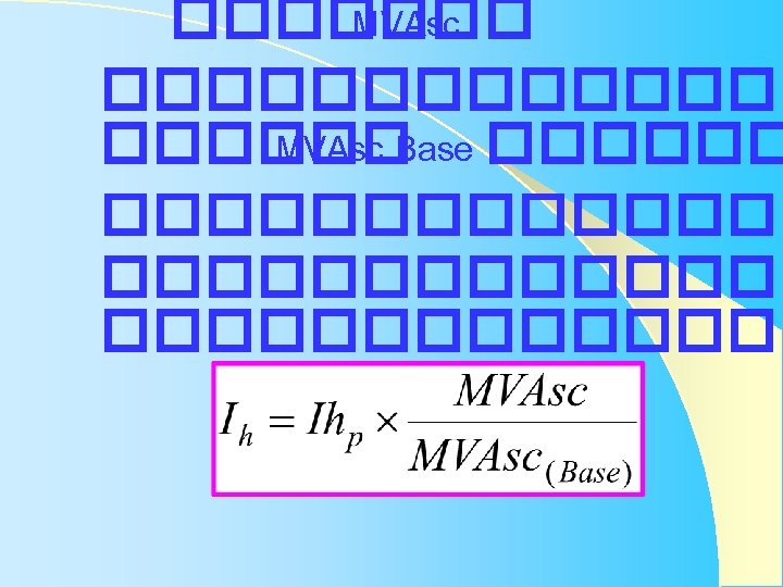
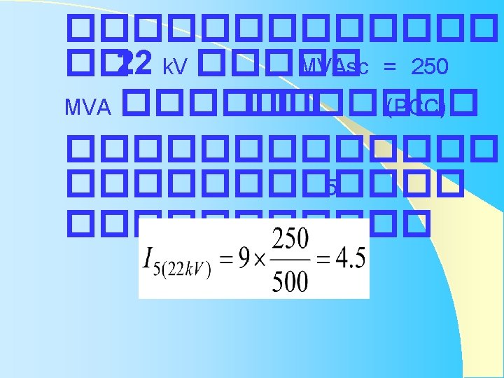
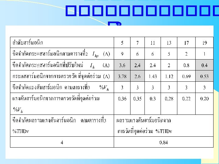
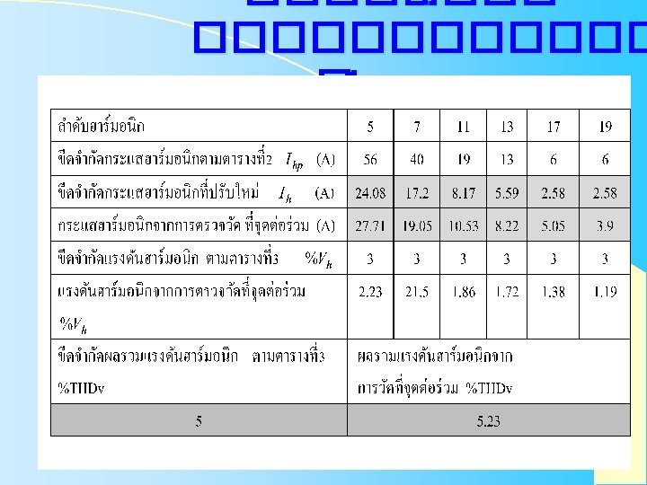
Harmonic Assessment IEEE 141 -1993 MVASC ; Short-circuit capacity l MVAH ; Power rating for load harmonic l
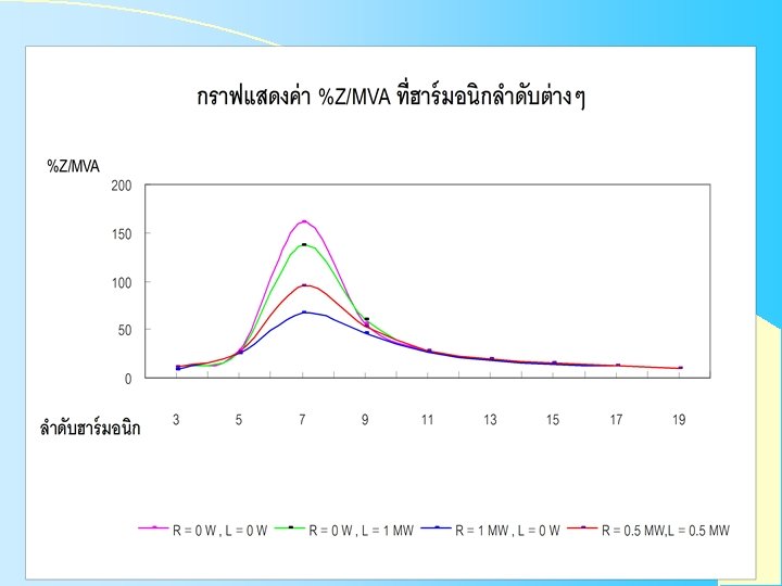
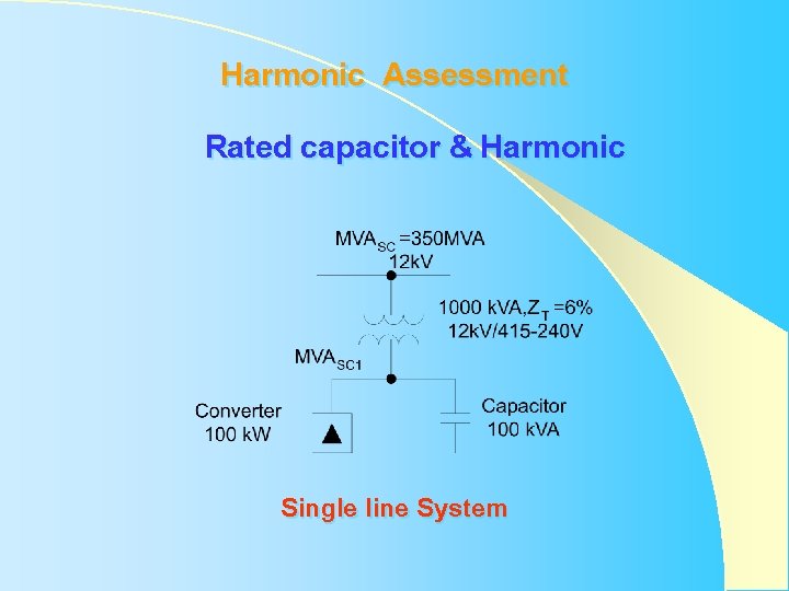
Harmonic Assessment Rated capacitor & Harmonic Single line System
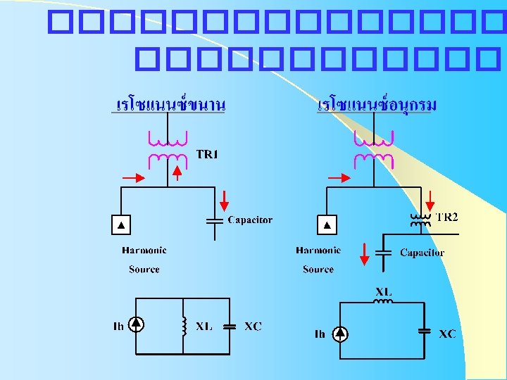
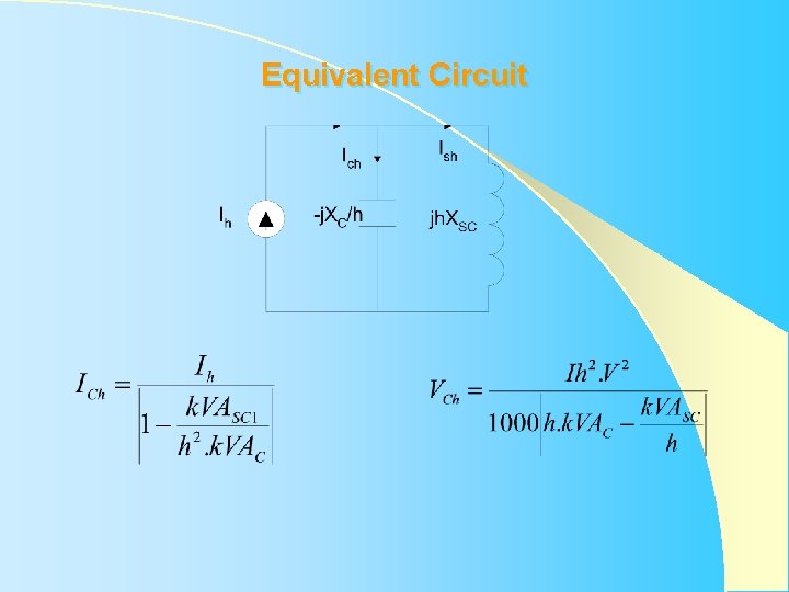
Equivalent Circuit
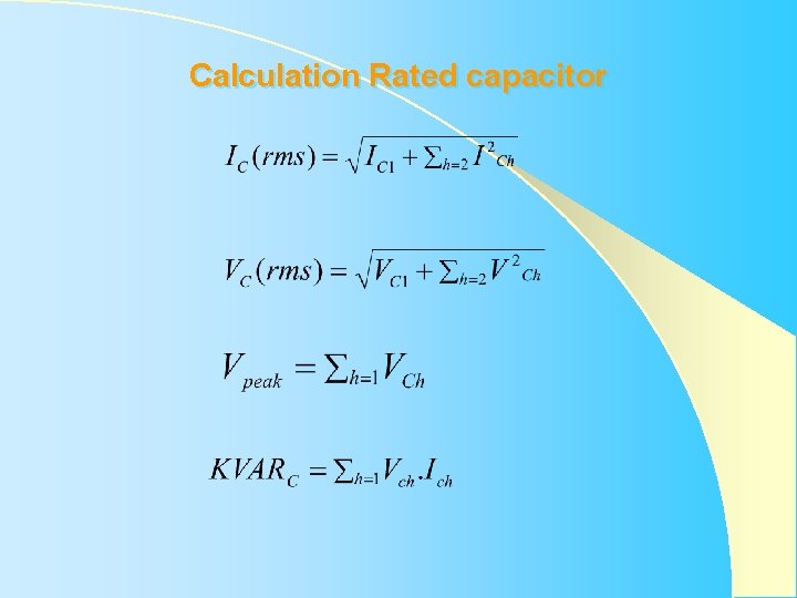
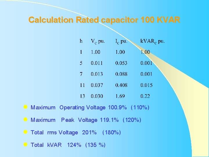
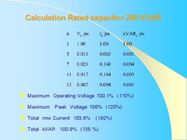
Calculation Rated capacitor
Rated Capacitor IEEE Std. 18 -1992 l l Maximum Operating Voltage 110% of Rated rms Voltage Maximum Peak Voltage 120% of Rated Peak Voltage Total rms Current 180% of Rated rms Current Total k. VAR 135% of Rated k. VAR
Calculation Rated capacitor 100 KVAR l l Maximum Operating Voltage 100. 9% (110%) Maximum Peak Voltage 119. 1% (120%) Total rms Voltage 201% (180%) Total k. VAR 124% (135 %)
Calculation Rated capacitor 200 KVAR l l Maximum Operating Voltage 100. 1% (110%) Maximum Peak Voltage 106% (120%) Total rms Current 103. 6% (180%) Total k. VAR 100. 9% (135 %)
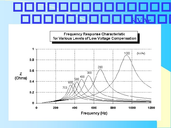
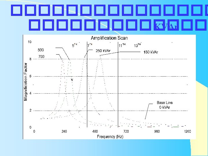
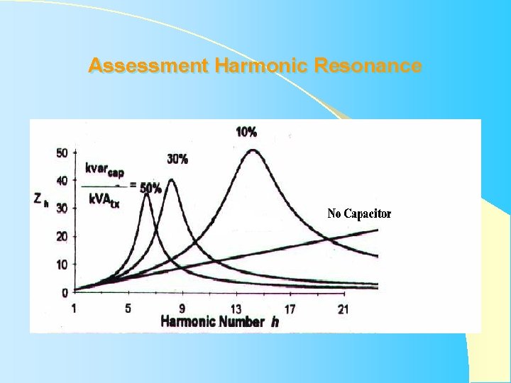
Assessment Harmonic Resonance
���������� I EC 1000 -4 -7 General guide on harmonic end interharmonics measurement and instrumentation, For power supply systems and equipment connected thereto
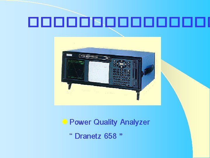
�������� l Power Quality Analyzer “ Dranetz 658 ”
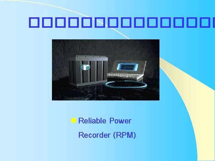
�������� l Reliable Power Recorder (RPM)
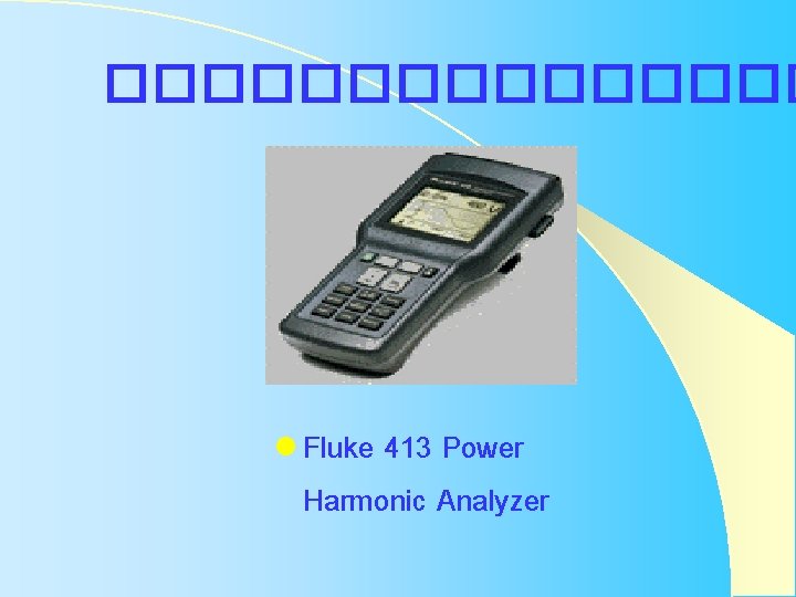
�������� l Fluke 413 Power Harmonic Analyzer
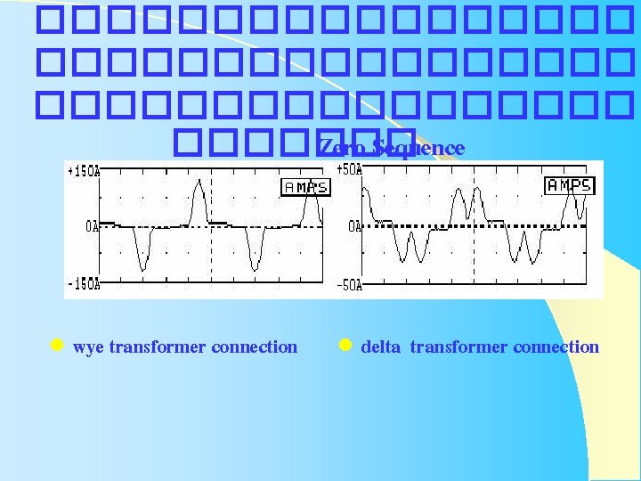
������������������ ������� Zero Sequence l wye transformer connection l delta transformer connection
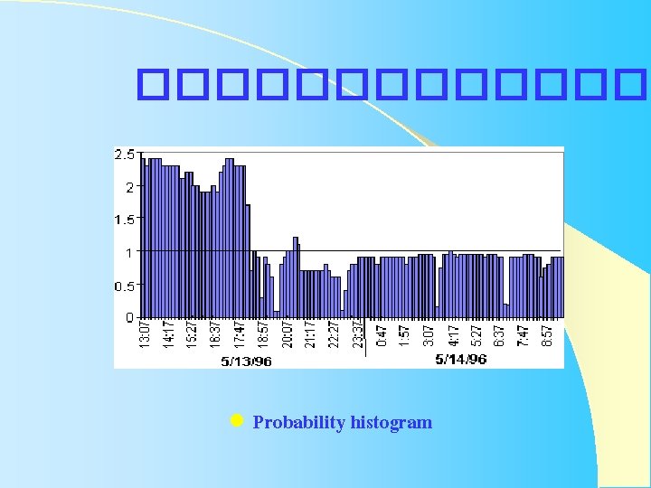
������� l Probability histogram
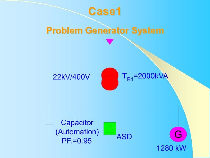
Case 1 Problem Generator System
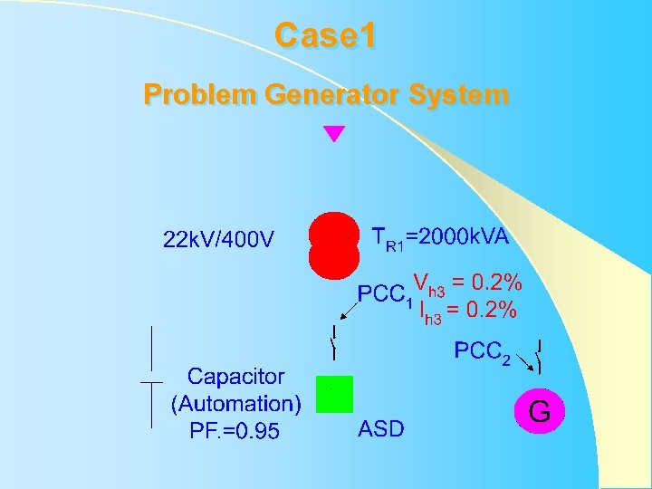
Case 1 Problem Generator System
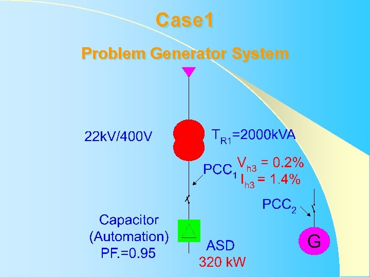
Case 1 Problem Generator System
Case 1 Problem Generator System
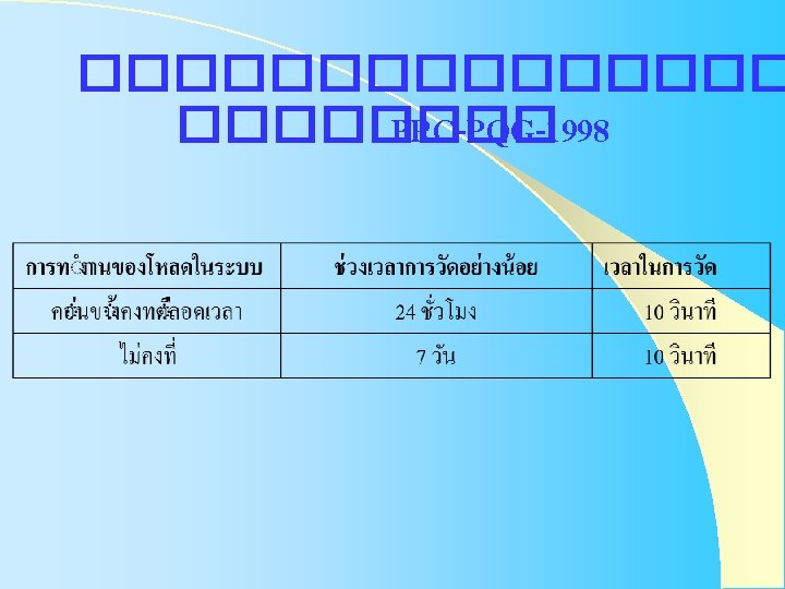
PRC-PQG-01 -1998 ������� ����� Power system Reliability Committee : PRC ������������ Power Quality working Group : PQG
������ Engineering Recommendation G. 5/3 September 1976 The Electricity Council Chief Engineer Conference “Limits for Harmonics in The United Kingdom Electricity Supply System”
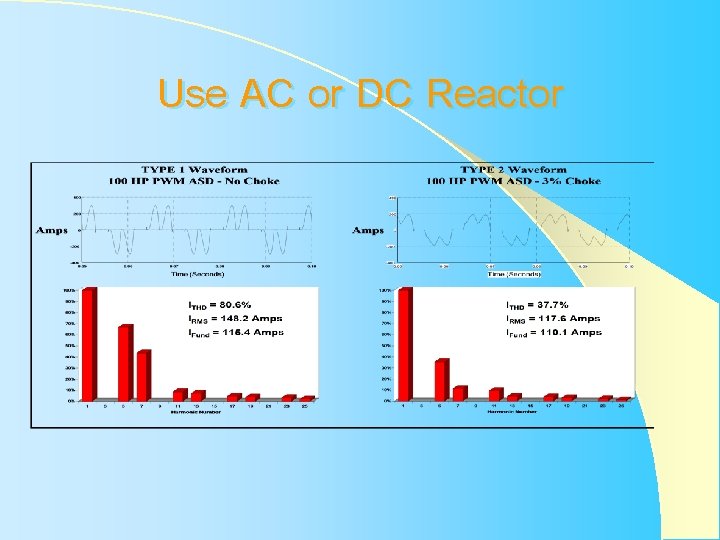
Evaluate of Solution to Harmonic Problems l Use AC or DC Reactor l Use Multiple-pulsing l Use Passive Harmonic Filter l Use Active Harmonic Filter
Use AC or DC Reactor
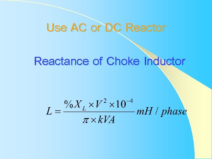
Use AC or DC Reactor Reactance of Choke Inductor
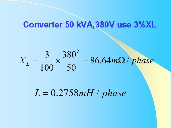
Converter 50 k. VA, 380 V use 3%XL
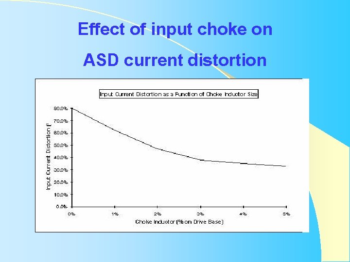
Effect of input choke on ASD current distortion
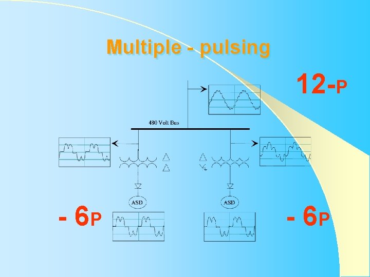
Multiple - pulsing - 6 P 12 -P - 6 P
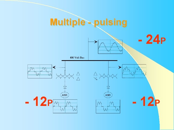
Multiple - pulsing - 12 P - 24 P - 12 P
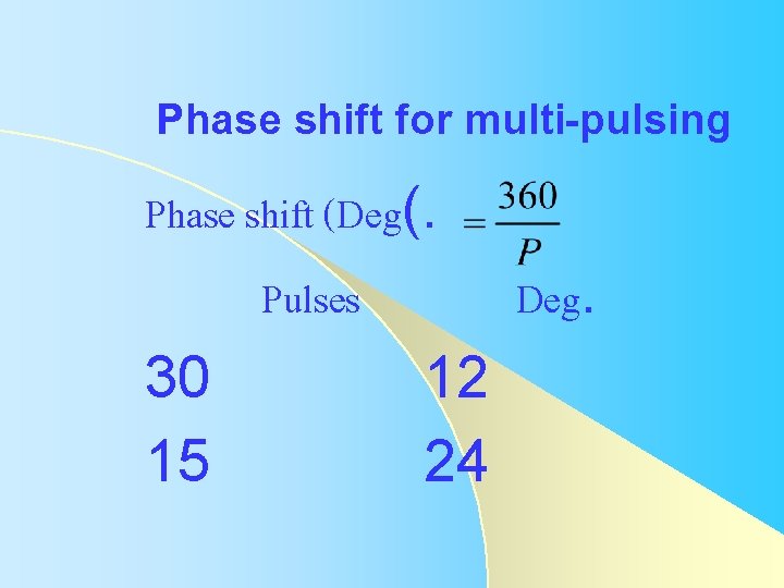
Phase shift for multi-pulsing Phase shift (Deg(. Pulses Deg. 30 12 15 24
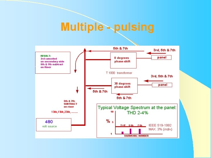
Multiple - pulsing
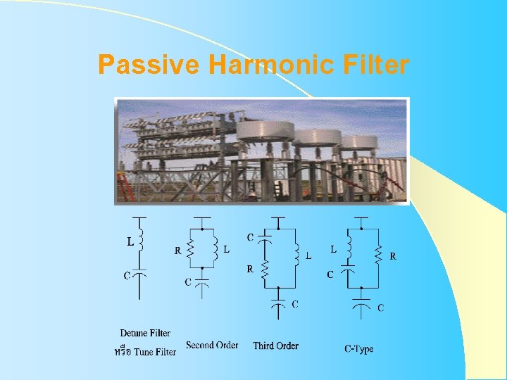
Passive Harmonic Filter
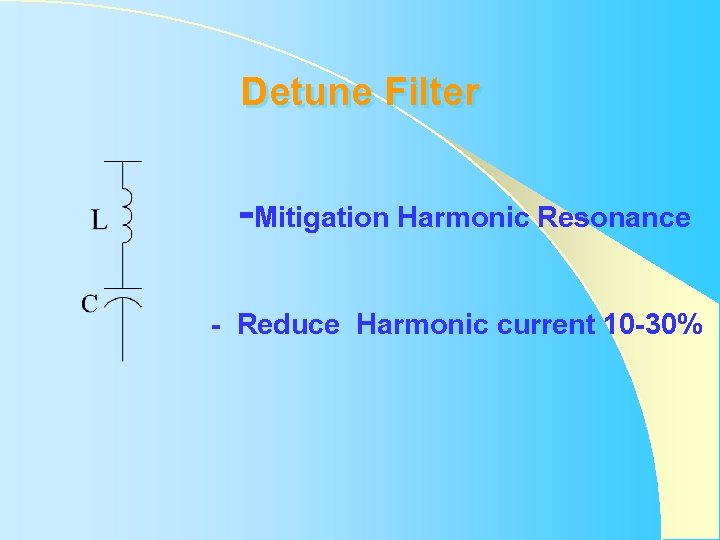
Detune Filter -Mitigation Harmonic Resonance - Reduce Harmonic current 10 -30%
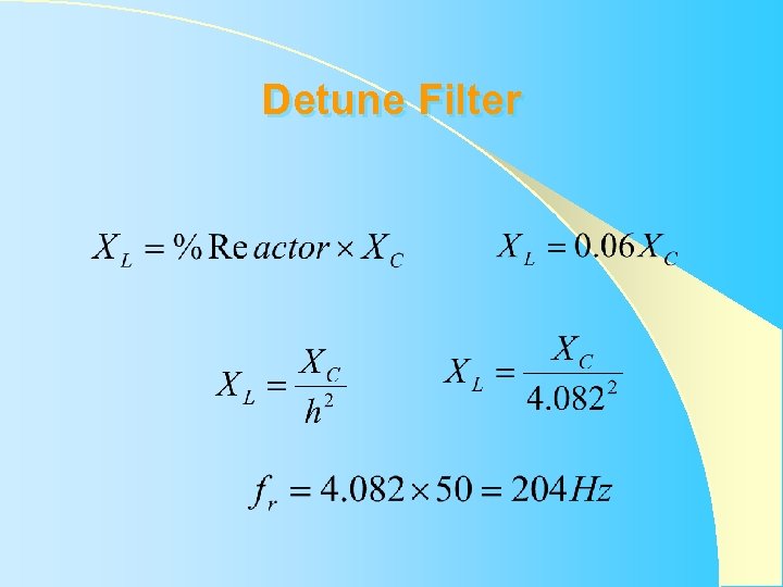
Detune Filter
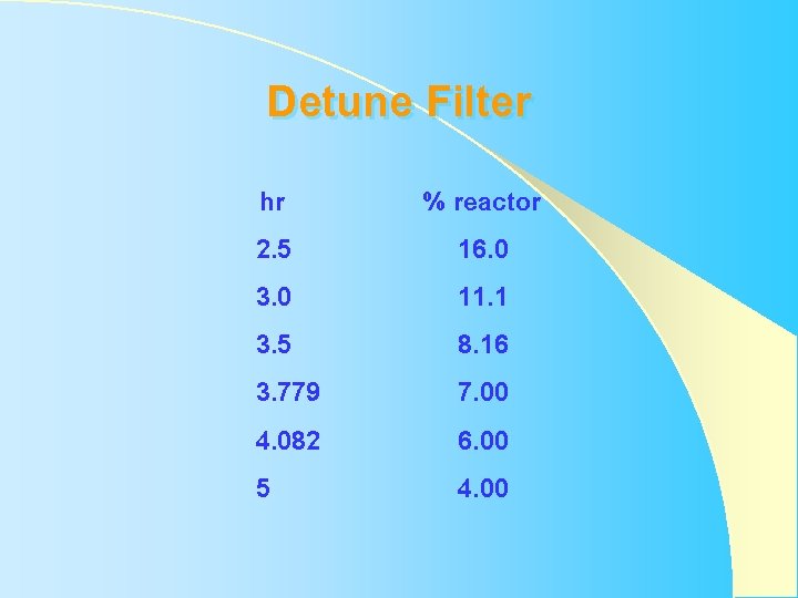
Detune Filter hr 2. 5 3. 0 3. 5 3. 779 4. 082 5 % reactor 16. 0 11. 1 8. 16 7. 00 6. 00 4. 00
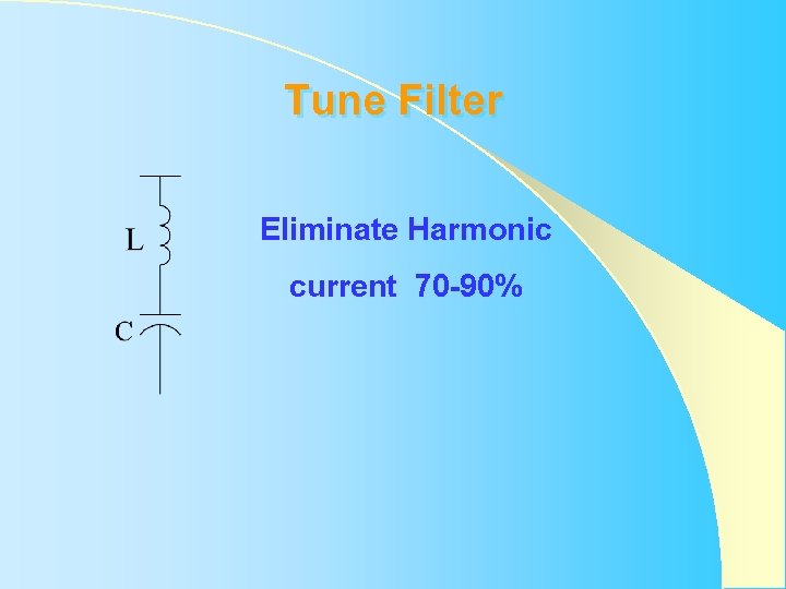
Tune Filter Eliminate Harmonic current 70 -90%
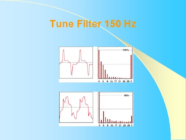
Tune Filter 150 Hz
Basic Tune Filter Design -Harmonic Current -Reactive Filter -Limitation -Voltage and Current Capacitor -Interaction System
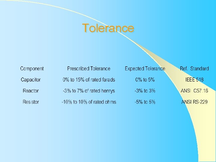
Tolerance
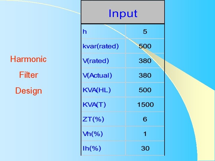
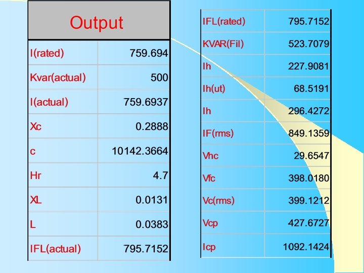
Harmonic Filter Design
Rated Capacitor IEEE Std. 18 -1992
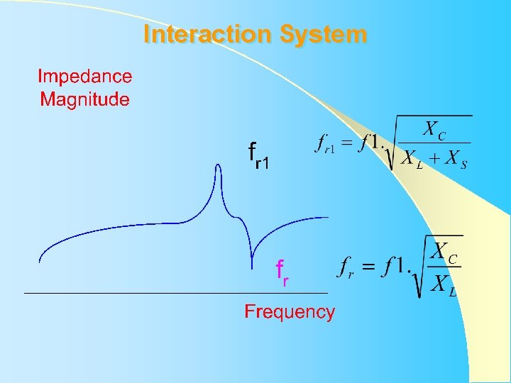
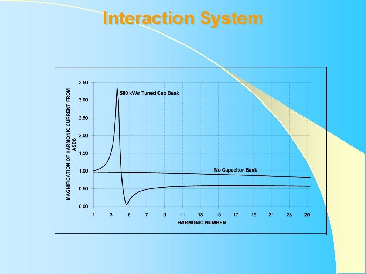
Interaction System
Interaction System
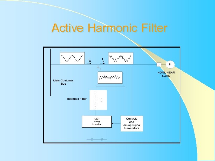
Active Harmonic Filter
��������� ������ �� Tel 590 - 5577 Fax 590 -5810 E-mail mgrrsd@pea. or. th n_sakchai@hotmail. com