TORSION CO 2 ABILITY TO ANALYZE TORQUELOADED MEMBER

TORSION CO 2 : ABILITY TO ANALYZE TORQUE-LOADED MEMBER AND EVALUATE THE VALUES AND DISTRIBUTION OF BENDING AND SHEAR STRESSES IN BEAM SECTION.

Torsion of Shafts are structural members with length significantly greater than the largest cross-sectional dimension used in transmitting torque from one plane to another.

Internal Torque T = ∫A ρVd = ∫A ρτxθd. A Equation is independent of material model as it represents static equivalency between shear stress and internal torque on a cross-section
 to obtain a formula for the")
Theory for Circular Shafts Theory Objective • (i) to obtain a formula for the relative rotation (φ2 φ1) in terms of the internal torque T. • (ii) to obtain a formula for the shear stress τxθ in terms of the internal torque T.

Y r T 2 θ X Z X 1

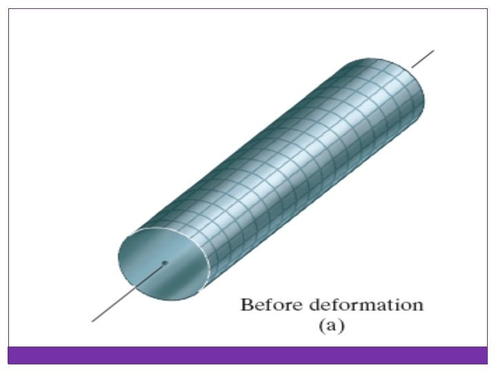
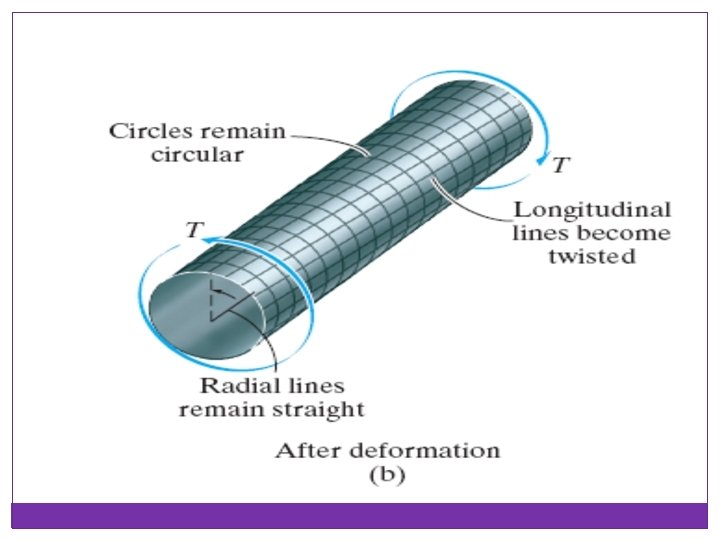
Kinematics Original Grid Deformed Grid

A 0 A 1 B 1 Φ Φ A 1 Ao, Bo —Initial position A 1, B 1 —Deformed position B 0

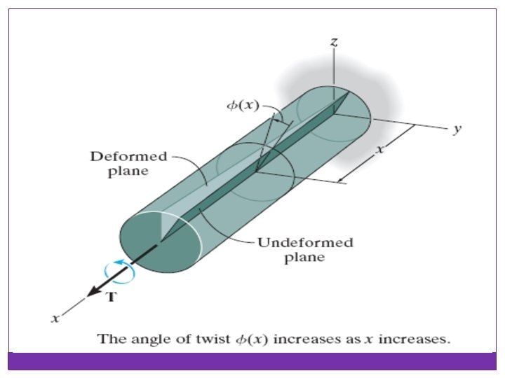
Assumption 1 - Plane sections perpendicular to the axis remain plane during deformation. (No Warping) Assumption 2 - On a cross-section, all radials lines rotate by equal angle during deformation. Assumption 3 - Radials lines remain straight during deformation. Φ = Φ(X) • Φ is positive counter-clockwise with respect to the x-axis.

Torsional Deformation of a Circular Shaft Torque is a moment that twists a member about its longitudinal axis. If the angle of rotation is small, the length of the shaft and its radius will remain unchanged.

Torsional Stresses and Strains In polar coordinates, all stress components except τxθ are assumed zero. Shear strain can be found from Hooke’s law. Direction of τxθ by inspection

Torsional Shear Stress

Torque Diagram • A torque force diagram is a plot of internal torque T vs. x • Internal torque jumps by the value of the external torque as one crosses the external torque from left to right. • An torsion template is used to determine the direction of the jump in T. A template is a free body diagram of a small segment of a shaft created by making an imaginary cut just before and just after the section where the external torque is applied.

Template 1 Template 2 Template 1 Equation Template 2 Equation T 2 = T 1 - Text T 2 = T 1 + Text

The Torsion Formula When material is linear-elastic, Hooke’s law applies. A linear variation in shear strain leads to a corresponding linear variation in shear stress along any radial line on the cross section. = maximum shear stress in the shaft = shear stress = resultant internal torque = polar moment of inertia of cross-sectional area = outer radius of the shaft = intermediate distance
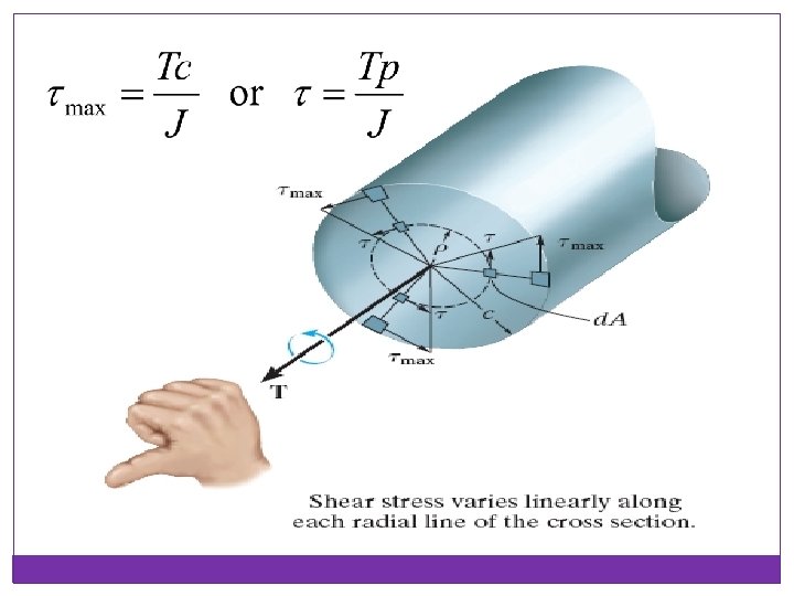

The Torsion Formula If the shaft has a solid circular cross section,

The Torsion Formula If a shaft has a tubular cross section,

Example 1 The solid shaft of radius c is subjected to a torque T. Find the fraction of T that is resisted by the material contained within the outer region of the shaft, which has an inner radius of c/2 and outer radius c.
")
Solution: Stress in the shaft varies linearly, thus The torque on the ring (area) located within the lighter-shaded region is For the entire lighter-shaded area the torque is

Solution: Using the torsion formula to determine the maximum stress in the shaft, we have Substituting this into Eq. 1 yields

Statically Indeterminate Shafts • Both ends of the shaft are built in, leading to two reaction torques but we have only on moment equilibrium equation. • The compatibility equation is that the relative rotation of the right wall with respect to the left wall is zero. • Calculate relative rotation of each shaft segment in terms of the reaction torque of the left (or right) wall. Add all the relative rotations and equate to zero to obtain reaction torque.

Example 2 The shaft is supported by two bearings and is subjected to three torques. Determine the shear stress developed at points A and B, located at section a–a of the shaft.

Solution: From the free-body diagram of the left segment, The polar moment of inertia for the shaft is

Since point A is at ρ = c = 75 mm, Likewise for point B, at ρ =15 mm, we have

Power Transmission Power is defined as the work performed per unit of time. For a rotating shaft with a torque, the power is

Power Transmission Since , the power equation is For shaft design, the design or geometric parameter is

Example 3 A solid steel shaft AB is to be used to transmit 3750 W from the motor M to which it is attached. If the shaft rotates at w =175 rpm and the steel has an allowable shear stress of allow τallow =100 MPa, determine the required diameter of the shaft to the nearest mm.

Solution: The torque on the shaft is Since As 2 c = 21. 84 mm, select a shaft having a diameter of 22 mm.

Angle of Twist Integrating over the entire length L of the shaft, we have Φ = angle of twist T(x) = internal torque J(x) = shaft’s polar moment of inertia G = shear modulus of elasticity for the material

Angle of Twist Assume material is homogeneous, G is constant, thus Sign convention is determined by right hand rule,

Example 4 The two solid steel shafts are coupled together using the meshed gears. Determine the angle of twist of end A of shaft AB when the torque 45 Nm is applied. Take G to be 80 GPa. Shaft AB is free to rotate within bearings E and F, whereas shaft DC is fixed at D. Each shaft has a diameter of 20 mm.

Solution: From free body diagram, Angle of twist at C is Since the gears at the end of the shaft are in mesh,

Since the angle of twist of end A with respect to end B of shaft AB caused by the torque 45 Nm, The rotation of end A is therefore

Example 5 The tapered shaft is made of a material having a shear modulus G. Determine the angle of twist of its end B when subjected to the torque.

Solution: From free body diagram, the internal torque is T.

Thus, at x, For angle of twist,

Example 6 The solid steel shaft has a diameter of 20 mm. If it is subjected to the two torques, determine the reactions at the fixed supports A and B.

Solution: By inspection of the free-body diagram, Since the ends of the shaft are fixed,

Using the sign convention, Solving Eqs. 1 and 2 yields TA = -345 Nm and TB = 645 Nm.

Solid Noncircular Shafts The maximum shear stress and the angle of twist for solid noncircular shafts are tabulated as next:
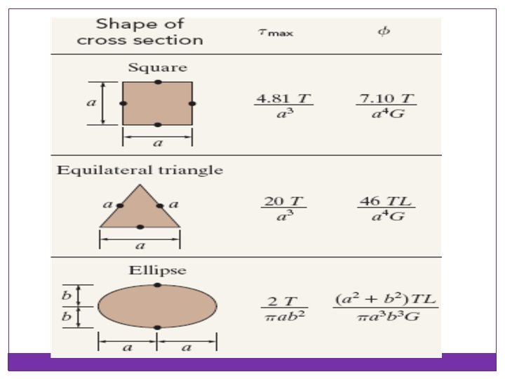

Example 7 The 6061 -T 6 aluminum shaft has a cross-sectional area in the shape of an equilateral triangle. Determine the largest torque T that can be applied to the end of the shaft if the allowable shear stress is τallow = 56 MPa and the angle of twist at its end is restricted to Φallow = 0. 02 rad. How much torque can be applied to a shaft of circular cross section made from the same amount of material? Gal = 26 GPa.

Solution: By inspection, the resultant internal torque at any cross section along the shaft’s axis is also T. By comparison, the torque is limited due to the angle of twist.

For circular cross section, we have

The limitations of stress and angle of twist then require Again, the angle of twist limits the applied torque.

Thin-Walled Tubes Having Closed Cross Sections Shear flow q is the product of the tube’s thickness and the average shear stress. Average shear stress for thin-walled tubes is τavg = average shear stress T = resultant internal torque at the cross section t = thickness of the tube Am = mean area enclosed boundary

Thin-Walled Tubes Having Closed Cross Sections For angle of twist,

Example 8 Calculate the average shear stress in a thin-walled tube having a circular cross section of mean radius rm and thickness t, which is subjected to a torque T. Also, what is the relative angle of twist if the tube has a length L?

Solution: The mean area for the tube is For angle of twist,

Example 9 A square aluminum tube has the dimensions. Determine the average shear stress in the tube at point A if it is subjected to a torque of 85 Nm. Also compute the angle of twist due to this loading. Take Gal = 26 GPa.

Solution: By inspection, the internal resultant torque is T = 85 Nm. The shaded area is For average shear stress,

For angle of twist, Integral represents the length around the centreline boundary of the tube, thus

Stress Concentration Torsional stress concentration factor, K, is used to simplify complex stress analysis. The maximum shear stress is then determined from the equation
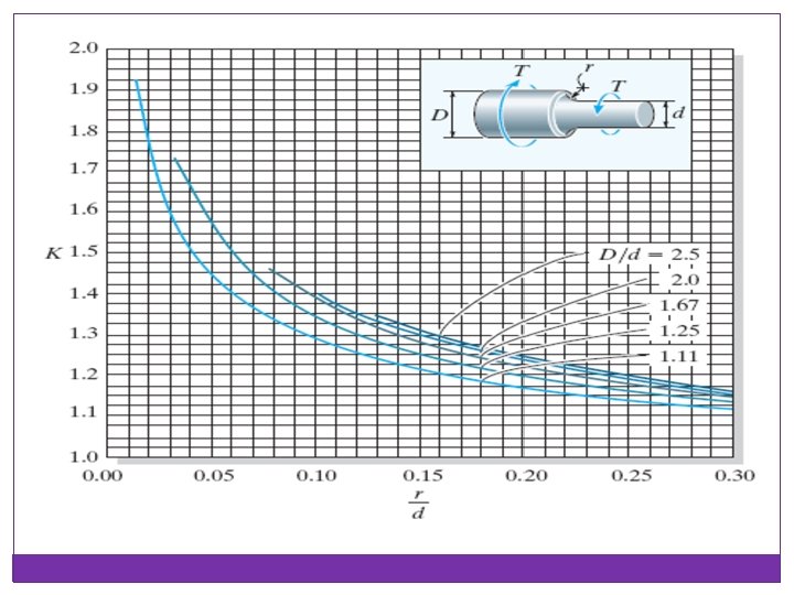

Example 10 The stepped shaft is supported by bearings at A and B. Determine the maximum stress in the shaft due to the applied torques. The fillet at the junction of each shaft has a radius of r = 6 mm.

Solution: By inspection, moment equilibrium about the axis of the shaft is satisfied The stress-concentration factor can be determined by the graph using the geometry,

Thus, K = 1. 3 and maximum shear stress is

Inelastic Torsion Considering the shear stress acting on an element of area d. A located a distance p from the center of the shaft,

Inelastic Torsion Shear–strain distribution over a radial line on a shaft is always linear. Perfectly plastic assumes the shaft will continue to twist with no increase in torque. It is called plastic torque.

Example 11 A solid circular shaft has a radius of 20 mm and length of 1. 5 m. The material has an elastic–plastic diagram as shown. Determine the torque needed to twist the shaft Φ = 0. 6 rad.

The maximum shear strain occurs at the surface of the shaft,

The radius of the elastic core can be obtained by Based on the shear– strain distribution, we have
- Slides: 65