
Topic 9 Wave phenomena AHL 9 3 Interference
- Slides: 35
Topic 9: Wave phenomena - AHL 9. 3 – Interference Topic 9. 3 is an extension of Topic 4. 4. Essential idea: Interference patterns from multiple slits and thin films produce accurately repeatable patterns. Nature of science: (1) Curiosity: Observed patterns of iridescence in animals, such as the shimmer of peacock feathers, led scientists to develop theory of thin film interference. (2) Serendipity: The first laboratory production of thin films was accidental.
Topic 9: Wave phenomena - AHL 9. 3 – Interference Understandings: • Young’s double-slit experiment • Modulation of two-slit interference pattern by one-slit diffraction effect • Multiple slit and diffraction grating interference patterns • Thin film interference
Topic 9: Wave phenomena - AHL 9. 3 – Interference Applications and skills: • Qualitatively describing two-slit interference patterns, including modulation by one-slit diffraction effect • Investigating Young’s double-slit experimentally • Sketching and interpreting intensity graphs of doubleslit interference patterns • Solving problems involving the diffraction grating equation • Describing conditions necessary for constructive and destructive interference from thin films, including phase change at interface and effect of refractive index • Solving problems involving interference from thin films
Topic 9: Wave phenomena - AHL 9. 3 – Interference Guidance: • Students should be introduced to interference patterns from a variety of coherent sources such as (but not limited to) electromagnetic waves, sound and simulated demonstrations • Diffraction grating patterns are restricted to those formed at normal incidence • The treatment of thin film interference is confined to parallel-sided films at normal incidence • The constructive interference and destructive interference formulae listed below and in the data booklet apply to specific cases of phase changes at interfaces and are not generally true
Topic 9: Wave phenomena - AHL 9. 3 – Interference Data booklet reference: • n = d sin • Constructive interference: 2 dn = (m + ½) • Destructive interference: 2 dn = m Theory of knowledge: • Most two-slit interference descriptions can be made without reference to the one-slit modulation effect. To what level can scientists ignore parts of a model for simplicity and clarity? Utilization: • Compact discs are a commercial example of the use of diffraction gratings • Thin films are used to produce anti-reflection coatings
Topic 9: Wave phenomena - AHL 9. 3 – Interference Aims: • Aim 4: two scientific concepts (diffraction and interference) come together in this sub-topic, allowing students to analyze and synthesize a wider range of scientific information • Aim 6: experiments could include (but are not limited to): observing the use of diffraction gratings in spectroscopes; analysis of thin soap films; sound wave and microwave interference pattern analysis • Aim 9: the ray approach to the description of thin film interference is only an approximation. Students should recognize the limitations of such a visualization
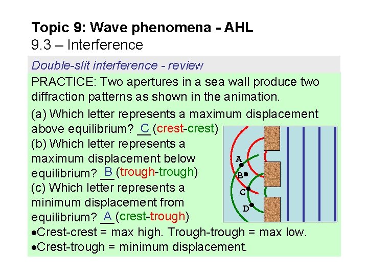
Topic 9: Wave phenomena - AHL 9. 3 – Interference Double-slit interference - review PRACTICE: Two apertures in a sea wall produce two diffraction patterns as shown in the animation. (a) Which letter represents a maximum displacement C (crest-crest) above equilibrium? __ (b) Which letter represents a A maximum displacement below B (trough-trough) equilibrium? __ B (c) Which letter represents a C minimum displacement from D A (crest-trough) equilibrium? __ Crest-crest = max high. Trough-trough = max low. Crest-trough = minimum displacement.
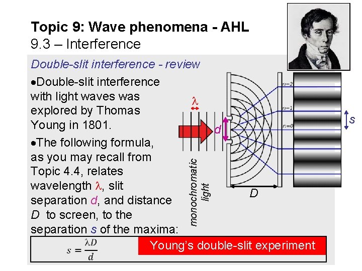
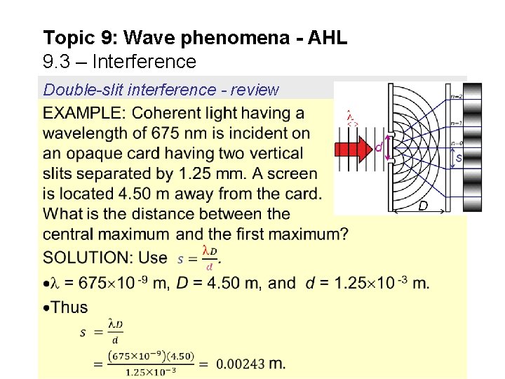
Topic 9: Wave phenomena - AHL 9. 3 – Interference monochromatic light Double-slit interference - review Double-slit interference with light waves was explored by Thomas s Young in 1801. d The following formula, as you may recall from Topic 4. 4, relates wavelength , slit D separation d, and distance D to screen, to the separation s of the maxima: Young’s double-slit experiment
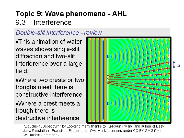
Topic 9: Wave phenomena - AHL 9. 3 – Interference Double-slit interference - review This animation of water waves shows single-slit diffraction and two-slit interference over a large s field. Where two crests or two troughs meet there is constructive interference. Where a crest meets a trough there is destructive interference. "Doubleslit 3 Dspectrum" by Lookang many thanks to Fu-Kwun Hwang and author of Easy Java Simulation - Francisco Esquembre - Own work. Licensed under CC BY-SA 3. 0 via Wikimedia Commons -
Topic 9: Wave phenomena - AHL 9. 3 – Interference Double-slit interference - review
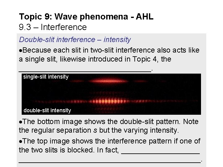
Topic 9: Wave phenomena - AHL 9. 3 – Interference Double-slit interference – intensity Because each slit in two-slit interference also acts like a single slit, likewise introduced in Topic 4, the ________________. single-slit intensity double-slit intensity The bottom image shows the double-slit pattern. Note the regular separation s but the varying intensity. The top image shows the interference pattern if one of the two slits is blocked. In fact, ________________________________.
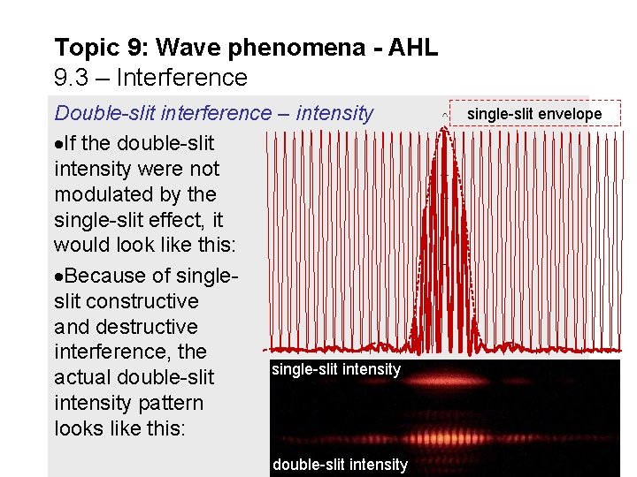
Topic 9: Wave phenomena - AHL 9. 3 – Interference single-slit envelope Double-slit interference – intensity If the double-slit intensity were not modulated by the single-slit effect, it would look like this: Because of single- slit constructive and destructive interference, the single-slit intensity actual double-slit intensity pattern looks like this: double-slit intensity
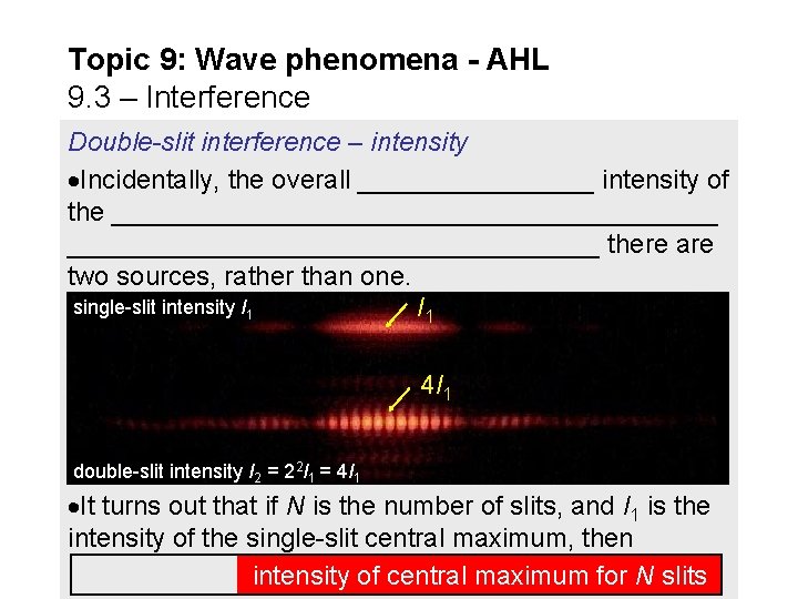
Topic 9: Wave phenomena - AHL 9. 3 – Interference Double-slit interference – intensity Incidentally, the overall ________ intensity of the _____________________ there are two sources, rather than one. single-slit intensity I 1 4 I 1 double-slit intensity I 2 = 22 I 1 = 4 I 1 It turns out that if N is the number of slits, and I 1 is the intensity of the single-slit central maximum, then intensity of central maximum for N slits
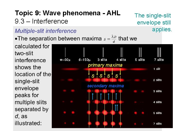
Topic 9: Wave phenomena - AHL 9. 3 – Interference primary maxima s s secondary maxima The single-slit envelope still applies.
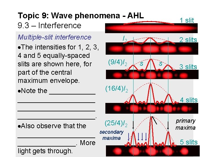
Topic 9: Wave phenomena - AHL 9. 3 – Interference 1 slit Multiple-slit interference I 2 2 slits The intensities for 1, 2, 3, 4 and 5 equally-spaced (9/4)I 2 s s slits are shown here, for 3 slits part of the central maximum envelope. (16/4)I 2 Note the ______ __________ 4 slits __________ __________. primary (25/4)I 2 Also observe that the maxima secondary __________ maxima 5 slits ________. More light gets through.
Topic 9: Wave phenomena - AHL 9. 3 – Interference Multiple-slit interference
Topic 9: Wave phenomena - AHL 9. 3 – Interference Multiple-slit interference
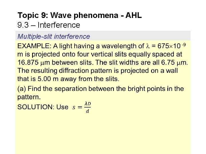
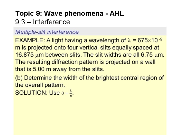
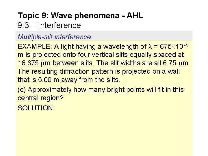
Topic 9: Wave phenomena - AHL 9. 3 – Interference Multiple-slit interference EXAMPLE: A light having a wavelength of = 675 10 -9 m is projected onto four vertical slits equally spaced at 16. 875 m between slits. The slit widths are all 6. 75 m. The resulting diffraction pattern is projected on a wall that is 5. 00 m away from the slits. (c) Approximately how many bright points will fit in this central region? SOLUTION:
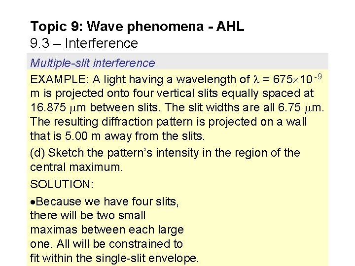
Topic 9: Wave phenomena - AHL 9. 3 – Interference Multiple-slit interference EXAMPLE: A light having a wavelength of = 675 10 -9 m is projected onto four vertical slits equally spaced at 16. 875 m between slits. The slit widths are all 6. 75 m. The resulting diffraction pattern is projected on a wall that is 5. 00 m away from the slits. (d) Sketch the pattern’s intensity in the region of the central maximum. SOLUTION: Because we have four slits, there will be two small maximas between each large one. All will be constrained to fit within the single-slit envelope.
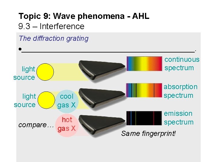
Topic 9: Wave phenomena - AHL 9. 3 – Interference The diffraction grating ______________________. continuous spectrum light source absorption spectrum light cool source gas X emission hot spectrum compare… gas X Same fingerprint!
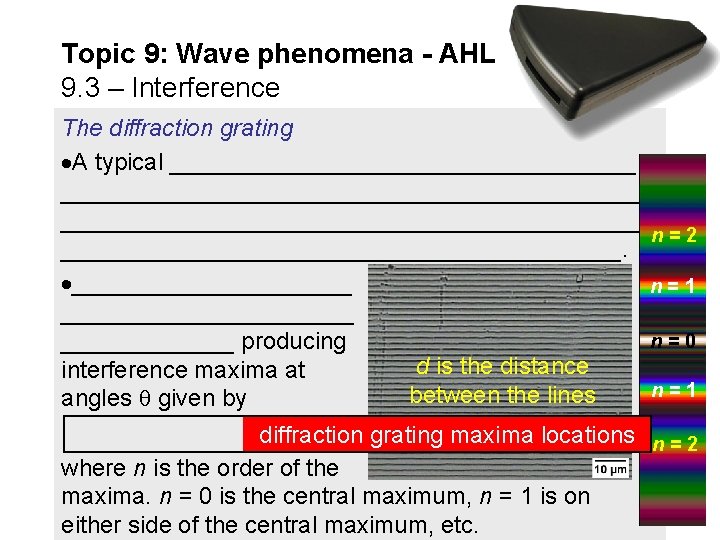
Topic 9: Wave phenomena - AHL 9. 3 – Interference The diffraction grating A typical ________________________________________ n=2 _____________________. ___________ n=1 ___________ n=0 _______ producing d is the distance interference maxima at n=1 between the lines angles given by diffraction grating maxima locations n = 2 where n is the order of the maxima. n = 0 is the central maximum, n = 1 is on either side of the central maximum, etc.
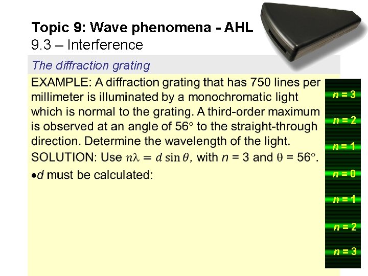
Topic 9: Wave phenomena - AHL 9. 3 – Interference The diffraction grating n=3 n=2 n=1 n=0 n=1 n=2 n=3
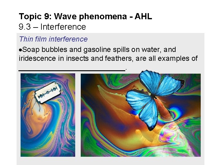
Topic 9: Wave phenomena - AHL 9. 3 – Interference Thin film interference Soap bubbles and gasoline spills on water, and iridescence in insects and feathers, are all examples of _____________.
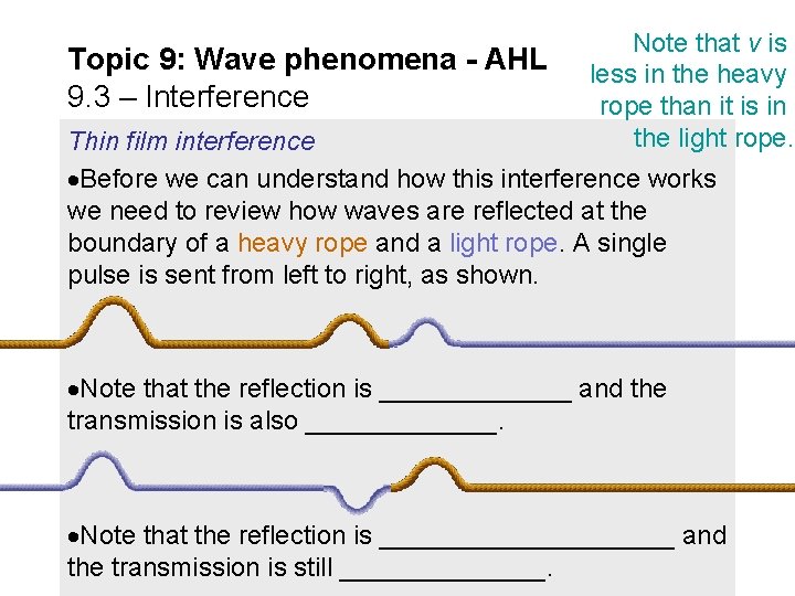
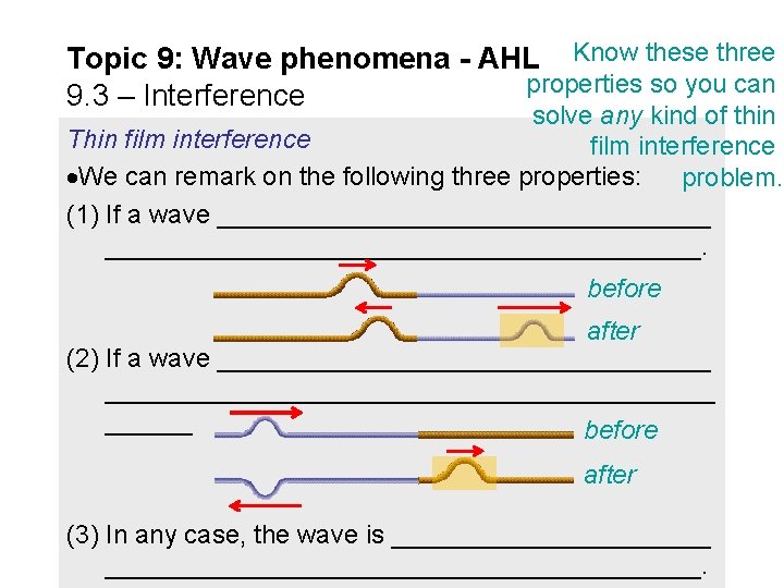
Topic 9: Wave phenomena - AHL 9. 3 – Interference Note that v is less in the heavy rope than it is in the light rope. Thin film interference Before we can understand how this interference works we need to review how waves are reflected at the boundary of a heavy rope and a light rope. A single pulse is sent from left to right, as shown. Note that the reflection is _______ and the transmission is also _______. Note that the reflection is __________ and the transmission is still _______.
Topic 9: Wave phenomena - AHL Know these three properties so you can 9. 3 – Interference solve any kind of thin Thin film interference We can remark on the following three properties: problem. (1) If a wave _________________________________________. before after (2) If a wave ______________________________________ before after (3) In any case, the wave is ________________________________.
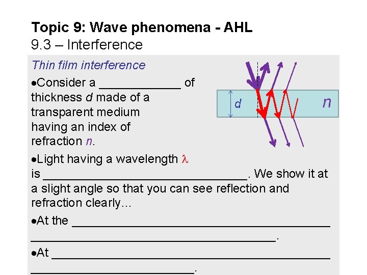
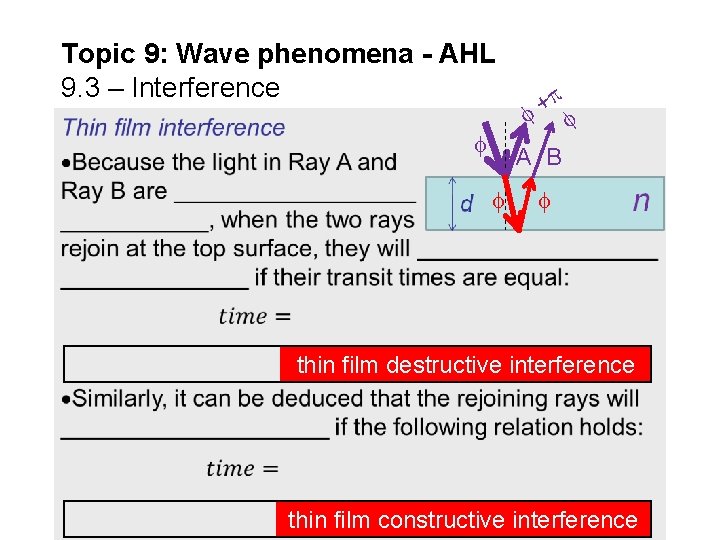
Topic 9: Wave phenomena - AHL 9. 3 – Interference Thin film interference Consider a ______ of thickness d made of a transparent medium having an index of refraction n. Light having a wavelength is _______________. We show it at a slight angle so that you can see reflection and refraction clearly… At the ___________________. At _____________________.
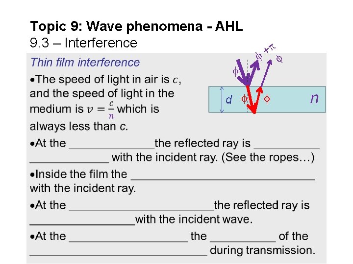
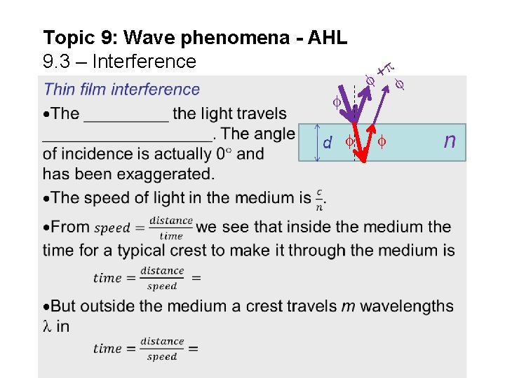
Topic 9: Wave phenomena - AHL 9. 3 – Interference +
Topic 9: Wave phenomena - AHL 9. 3 – Interference +
Topic 9: Wave phenomena - AHL 9. 3 – Interference + A B thin film destructive interference thin film constructive interference
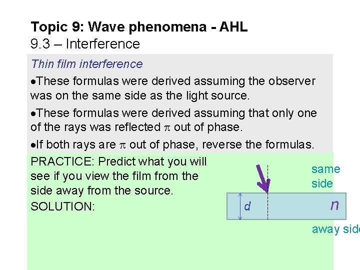
Topic 9: Wave phenomena - AHL 9. 3 – Interference Thin film interference These formulas were derived assuming the observer was on the same side as the light source. These formulas were derived assuming that only one of the rays was reflected out of phase. If both rays are out of phase, reverse the formulas. PRACTICE: Predict what you will same see if you view the film from the side away from the source. SOLUTION: away side
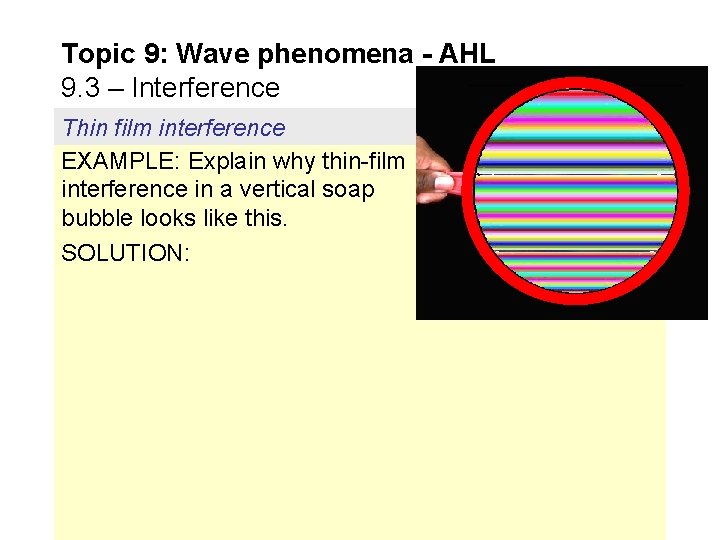
Topic 9: Wave phenomena - AHL 9. 3 – Interference Thin film interference EXAMPLE: Explain why thin-film interference in a vertical soap bubble looks like this. SOLUTION:
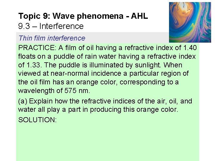
Topic 9: Wave phenomena - AHL 9. 3 – Interference Thin film interference PRACTICE: A film of oil having a refractive index of 1. 40 floats on a puddle of rain water having a refractive index of 1. 33. The puddle is illuminated by sunlight. When viewed at near-normal incidence a particular region of the oil film has an orange color, corresponding to a wavelength of 575 nm. (a) Explain how the refractive indices of the air, oil, and water all play a part in producing this orange color. SOLUTION:
Topic 9: Wave phenomena - AHL 9. 3 – Interference Thin film interference PRACTICE: Continued. . . (b) Calculate the possible thicknesses of the film in the orange region. SOLUTION:
Topic 9: Wave phenomena - AHL 9. 3 – Interference Thin film interference PRACTICE: A film of oil having a refractive index of 1. 40 floats on a puddle of rain water having a refractive index of 1. 33. The puddle is illuminated by sunlight. When viewed at near-normal incidence a particular region of the oil film has an orange color, corresponding to a wavelength of 575 nm. (c) Calculate the minimum thickness of the film in the orange region. SOLUTION:
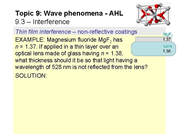
Topic 9: Wave phenomena - AHL 9. 3 – Interference Thin film interference – non-reflective coatings EXAMPLE: Magnesium fluoride Mg. F 2 has n = 1. 37. If applied in a thin layer over an optical lens made of glass having n = 1. 38, what thickness should it be so that light having a wavelength of 528 nm is not reflected from the lens? SOLUTION: