TOPIC 10 Sintering pressureassisted sintering pressure electric field
")
 – the name of a metallurgy field: powder metallurgy")


 they have")


 modeling of temperature fields at SPS Zr. O 2 at")


 47. 4 ± 4. 5")

")


- Slides: 29
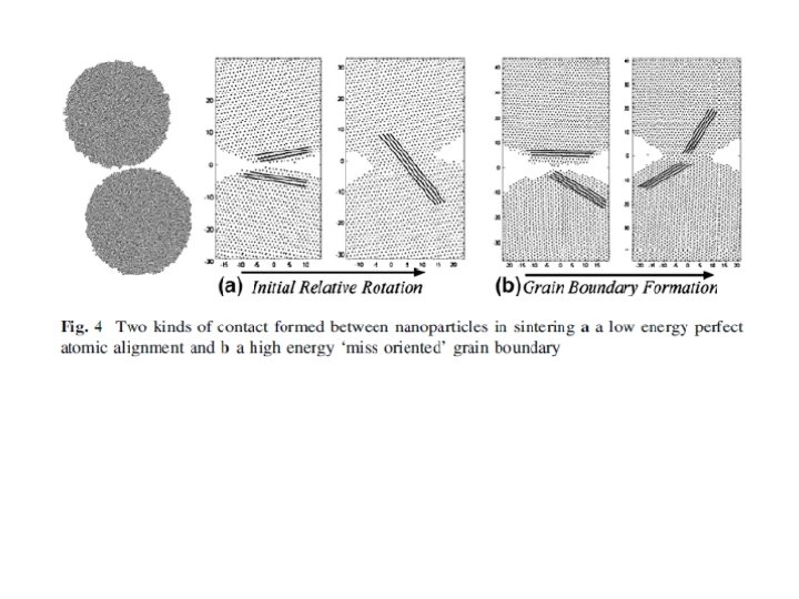
TOPIC 10 Sintering, pressure-assisted sintering & pressure + electric field -assisted sintering (SPS technique) for production of nanomaterials (doc. Ing. Pavel Ctibor, Ph. D. ) Sintering is the process of forming a solid mass of material by heat without melting it. The atoms in the materials diffuse across the boundaries of the particles, fusing the particles together and creating one solid piece (bulk).
Starting materials - Metallic powder(s) – the name of a metallurgy field: powder metallurgy - Ceramic powder(s) – conventional sintering (more frequent than casting); typically pressureless sintering - If pressure is applied – hot pressing - Carbide (ceramic) powder plus metallic binder – name of the product: sintered carbide (metallic binder is often re-melted during sintering) During the firing process, atomic diffusion drives powder surface elimination in different stages, starting from the formation of necks between powders to final elimination of small pores at the end of the process. The driving force for densification is the change in free energy from the decrease in surface area and lowering of the surface free energy by the replacement of solid-vapor interfaces. It forms new but lower-energy solid-solid interfaces with a total decrease in free energy. The change in energy is much higher when the radius of curvature is less than a few micrometres, which is one of the main reasons why much ceramic technology is based on the use of few micrometer -particle materials.
Example – Calcium titanate spherical particles sintered in air
Example – Barium titanate irregular particles sintered in air
Due to the shifted positions of atoms at the grain boundary (GB) they have a higher energy state when compared with atoms in the crystal lattice of the grains. This makes it possible to selectively etch the GBs when one wants make the microstructure visible. Striving to minimize its energy leads to the coarsening of the microstructure. This involves minimizing its GB area and changing its topological structure to minimize its energy. This grain growth can either be normal or abnormal, a normal growth is characterized by the uniform growth and size of all the grains in the specimen. Abnormal growth is when a few grains grow much larger than all the remaining. Al 2 O 3: Grain growth for 500 times (40 nm to 20 μm)! Suppression by Mg. F 2 additive
Creating ceramic objects via sintering of powders includes: Mixing water, binder, deflocculant, and unfired ceramic powder to form a slurry; Spray-drying the slurry; Putting the spray dried powder into a mold and pressing it to form a green body (an unsintered ceramic item); Heating the green body at low temperature to burn off the binder (calcination); Sintering at a high temperature to fuse the ceramic particles together Sintering is associated with a remarkable shrinkage of the material. Sintering mechanisms Surface diffusion – Diffusion of atoms along the surface of a particle Vapor transport – Evaporation of atoms which condense on a different surface Lattice diffusion from surface – atoms from the surface diffuse through the lattice DENSIFICATION Lattice diffusion from grain boundary – atoms from grain boundary diffuse through lattice Grain boundary diffusion – atoms diffuse along grain boundary Plastic deformation – dislocation motion causes flow of matter
An example of technological process based on sintering of sol-gel formed precursor The Zr 0. 8 Sn 0. 2 Ti. O 4 ceramic materials are typically prepared by the sol-gel technique. Zirconium oxychloride (Zr. OCl 2. 8 H 2 O), Titanium isopropoxide C 12 H 28 O 4 Ti and Tin nitrate Sn(NO 3)2 are used as the starting materials. Initially, Titanium isopropoxide is mixed with acetyl acetone and 2 -isopropanol solutions. Then, the second solution is prepared with zirconium oxychloride and methanol. Finally, tin nitrate is dissolved in an acetic acid and HNO 3 mixed solution. These three solutions are mixed together until a yellow colored sol is obtained. Then the sol is evaporated at 90°C for 2 hours till yellow gel was obtained. The obtained gel powder is then calcined at 800°C for 3 h, mixed with the poly vinyl alcohol binder, then pelletized into flat disks under e. g. 40 MPa pressure. These pellets are later sintered in a furnace at 1400°C for 3 hours holding time at a heating and cooling rate of about 10°C/min.
From: H. Zhang et al. , Optical Properties and Microstructure of Nanocrystalline Cubic Zirconia Prepared by High-Pressure Spark Plasma Sintering, J. Am. Ceram. Soc. , 94 [9] 2981– 2986 (2011). Example of a triple junction (connection of 3 grains) 1100°C, 400 MPa HRTEM observation revealed that glassy phase (thickness of 1– 2 nm), similar to that in Si 3 N 4, existed at the Si. C / Si. C grain boundaries. From: Y. Shinoda, Y. Suzuki, K. Yoshida, TEM analysis of nanocrystalline Si. C ceramics sintered by SPS using Al 2 O 3–Ti. O 2 additive, J. Asian Ceram. Soc. , 1 [3] 2013, 267 -273.
Both pore types: on the grain boundaries; inside grains Pores inside grains partly eliminated; but a new phase From: V. M. Ferreira et al, J. Mater. Res. , Vol. 12, No. 12 (1997) 3293 -3299
Nano-layered polytypes in Sr. Ti. O 3 Sr 3 Ti 2 O 7 / Sr 4 Ti 3 O 10 Neighbor layers have different stoichiometry From: S. Sturm, A. Recnik, M. Ceh, MICROSTRUCTURE EVOLUTION IN Sr. Ti. O 3 WITH DIFFERENT Sr/Ti RATIOS, Journal KOVINE, ZLITINE, TEHNOLOGIJE 33 (1999) 6, 479 -486.
Electric current assisted sintering These techniques employ electric currents to drive or enhance sintering. A. G. Bloxam (England), 1906, the first patent on sintering powders using direct current in vacuum. The primary purpose was the production of filaments for incandescent lamps by compacting tungsten or molybdenum particles. The applied current was particularly effective in reducing surface oxides that increased the emissivity of the filaments. Weintraub and Rush, 1913, patented a modified sintering method, which combined electric current with pressure. The benefits were proved for the sintering of refractory metals as well as conductive carbide or nitride powders. The starting boron–carbon or silicon–carbon powders were placed in an electrically insulating tube and compressed by two rods which also served as electrodes for the current. The estimated sintering temperature was 2000 °C.
Reducing grain growth If a dopant is added to the material (example: Nd in Ba. Ti. O 3) the impurity will tend to stick to the grain boundaries. As the grain boundary tries to move (as atoms jump from the convex to concave surface), it will result in a local change in concentration of the dopant. It slower the grain boundary movement. Porosity in sintered ceramics – Example: hot pressed Al 2 O 3 at 1600°C
Spark Plasma Sintering – SPS • Sintering technique also known as Field assisted sintering technique (FAST) or Pulsed electric current sintering (PECS) • Pulsed DC current passes directly through a graphite die, as well as the powder compact, in case of conductive samples.
Applied force up to 10 ton, graphite pistons can withstand pressure up to 80 MPa. Heat is generated internally, in contrast to the hot pressing, where the heat is provided by external heating elements. - This facilitates a very high heating rate (up to 1000 K/min). Hence the sintering process generally is very fast -> fully dense materials in few minutes. The general speed of the process ensures it for densifying powders with nanosize grains while avoiding grain coarsening that accompanies standard densification routes. Temperature measurement either by thermocouple or pyrometer (up to 2200/2400 °C).
Finite element method (FEM) modeling of temperature fields at SPS Zr. O 2 at 1500°C Ti. N at 1500°C
Mechanisms discussed in connection with SPS – Mechanical effects from externally applied mechanical load • Plastic deformation • Diffusion creep • Grain boundary sliding – Thermal effects • High heating rates => prevention of grain growth • Macro- and microscopic temperature gradients (local heating) – Electric and magnetic field effects and possibly plasma effects • only in case of conductive materials • Large number of possibly present mechanisms and their combination => There is no complex SPS sintering model available
Sinterability of conductive materials enhanced by external electric field The classical relationship relating the flux of the diffusing species i (Ji) and the concentration gradient (d ln. Ci / dx) gets modified in the presence of an external electric field (E), according to the following equation: F = 9. 648(24) x 104 C / mol where Di is the diffusivity of i, F is the Faraday constant, z* is the effective charge on i, R is the gas constant and T is the absolute temperature. This indicates that the rate of mass transport increases in the presence of an electric field and hence influences the reaction kinetics. Since the mobility of dislocations is enhanced under a pulsed electric field, it is also possible that the Ti. B 2 powder particles are partially deformed, under the applied pressure, at the contacts (neck region). This can result in widening of the contact area, bringing more particles in contact with each other. Additionally, skin current is generated due to the pulsed electric field. This skin current may result in enhanced migration and carry more molecules to the particle surfaces. A. Mukhopadhyay, T. Venkateswaran and B. Basu, Spark plasma sintering may lead to phase instability and inferior mechanical properties: A case study with Ti. B 2, Scripta Materialia 69 (2013) 159– 164.
From: T. B. Holland, U. Anselmi-Tamburini and A. K. Mukherjee, Electric fields and the future of scalability in SPS, Scripta Materialia 69 (2013) 117– 121. “No field” means a tube furnace - The heating speed has higher influence on the densification than the electric field.
WC without Co binder Microhardness (at 1 N load) 47. 4 ± 4. 5 GPa
Ba. Ti. O 3 T to C The decrease of area of the domain wall per volume with decreased tetragonal (T) content and the internal stress produced from phase transformation. From: B. Li et al. , Dielectric properties of fine-grained Ba. Ti. O 3 prepared by spark-plasma-sintering, Materials Chemistry and Physics 83 (2004) 23– 28.
SPS setup at IPP ASCR, producer Thermal Technology LLC (USA/Germany)
Multi-layer 7 layers Mix 100 Ti. O 2 80 60 Al 2 O 3 50 40 20 0
Multi-layer Layer 7 Ti. O 2 3 2 Layer 1 Al 2 O 3
Layer 2 Layer 3 boundary with Layer 1
Hanemann system for application of Vickers indents at 1 N load 20 indents for 1 average 2 indents for 1 average (i. e. 1 value per layer) (i. e. 8 values per layer) Left: Nothing unexpected Right: Probably Al 2 Ti. O 5 phase with lower hardness