
Tomahawk 2 ASIC Packet Walk and Platform Overview





- Slides: 85
Tomahawk 2 ASIC Packet Walk and Platform Overview Faraz Taifehesmatian CCIE R&S, DC Technical Marketing Engineer, INSBU April 2019
Agenda © 2017 2019 Cisco and/or its affiliates. All rights reserved. Cisco Confidential 1 ASIC Architecture 2 Forwarding 3 Buffering 4 CT vs SF 5 Platform Overview
Tomahawk 2 ASIC Architecture © 2019 Cisco and/or its affiliates. All rights reserved. Cisco Confidential
Tomahawk 2 ASIC © 2019 Cisco and/or its affiliates. All rights reserved. Cisco Confidential • ASIC Block • Forwarding Pipeline • Port Numbering • Single Pipeline Block • Memory Management Unit • Queuing and Scheduling • ASIC Comparison • TH 2 New Features
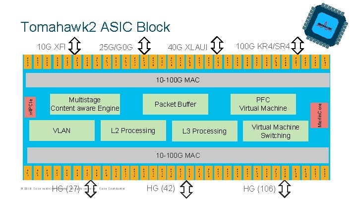
Tomahawk 2 ASIC Block 10 G XFI F C 3 3 F C 3 4 F C 3 5 F C 3 6 25 G/G 0 G F C 3 7 F C 3 8 F C 3 9 F C 4 0 F C 4 1 F C 4 2 F C 4 3 100 G KR 4/SR 4 40 G XLAUI F C 4 4 F C 4 5 F C 4 6 F C 4 7 F C 4 8 F C 4 9 F C 5 0 F C 5 1 F C 5 2 F C 5 3 F C 5 4 F C 5 5 F C 5 6 F C 5 7 F C 5 8 F C 5 9 F C 6 0 F C 6 1 F C 6 2 F C 6 3 F C 3 0 F C 3 1 F C 6 4 10 -100 G MAC L 2 Processing VLAN PFC Virtual Machine Packet Buffer Merlin. Core x 4 PCIe Multistage Content aware Engine Virtual Machine Switching L 3 Processing 10 -100 G MAC F C 1 F C 2 F C 3 F C 4 F C 5 F C 6 HG (27) F C 7 F C 8 F C 9 F C 1 0 F C 1 1 © 2019 Cisco and/or its affiliates. All rights reserved. Cisco Confidential F C 1 2 F C 1 3 F C 1 4 F C 1 5 F C 1 6 HG (42) F C 1 7 F C 1 8 F C 1 9 F C 2 0 F C 2 1 F C 2 2 F C 2 3 F C 2 4 F C 2 5 F C 2 6 F C 2 7 HG (106) F C 2 8 F C 2 9 F C 3 2
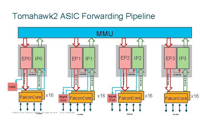
Tomahawk 2 ASIC Forwarding Pipeline MMU EP 0 IP 0 © 2019 Cisco and/or its affiliates. All rights reserved. Cisco Confidential Ser. Des x 16 Mgmt Port Falcon. Core Ser. Des x 16 Loopback Up to 32 Ports Falcon. Core Up to 32 Ports Mgmt Port Loopback EP 3 IP 3 Up to 32 Ports x 16 Loopback Up to 32 Ports Falcon. Core EP 2 IP 1 Up to 32 Ports Loopback Up to 32 Ports CMIC EP 1 Falcon. Core Ser. Des x 16
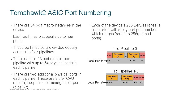
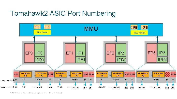
Tomahawk 2 ASIC Port Numbering • • • There are 64 port macro instances in the device Each port macro supports up to four ports • Each of the device’s 256 Ser. Des lanes is associated with a physical port number which ranges from 1 to 256(general ports) These port macros are divided equally across the four pipelines This results in 16 port macros per pipeline with up to 64 physical ports in each pipeline There are two additional physical ports in each pipeline. These are either CPU (pipe 0), Loopback, or management ports (pipe 1 -3) © 2019 Cisco and/or its affiliates. All rights reserved. Cisco Confidential To Pipeline 0 Local Port # CPU Port Macro (0) 0 1 -4 Macro … Port(15) 61 -64 LPBK 65 To Pipeline 1 -3 Port Macro (0) Local Port # 0 -3 Macro … Port(15) 60 -63 MGT LPBK 64 65
Tomahawk 2 ASIC Port Numbering XPE MMU XPE Slice Control EP 0 IP 0 EP 1 Port Macro (0) Macro … Port(15) LPBK Port Macro (0) EP 2 IP 1 Local Port # 0 1 -4 61 -64 65 0 -3 Global Port # 0 1 -4 … 61 -64 260 65 -69 © 2019 Cisco and/or its affiliates. All rights reserved. Cisco Confidential Macro … Port(15) 60 -63 … 125 -128 XPE Slice Control IDB 1 IDB 0 CPU XPE EP 3 IP 2 IDB 3 IDB 2 MGT LPBK 64 65 257 261 Port Macro (0) 0 -3 129 -132 Macro … Port(15) 60 -63 … 189 -192 IP 3 MGT LPBK Port Macro (0) 64 65 0 -3 259 262 193 -196 Macro … Port(15) 60 -63 … 253 -256 LPBK 64 65 258 263
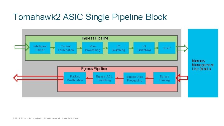
Tomahawk 2 ASIC Single Pipeline Block Ingress Pipeline Intelligent Parser Tunnel Termination Vlan Processing L 2 Switching L 3 Switching ICAP Memory Management Unit (MMU) Egress Pipeline Packet Modification © 2019 Cisco and/or its affiliates. All rights reserved. Cisco Confidential Egress ACL Switching Egress Vlan Processing Egress Parsing
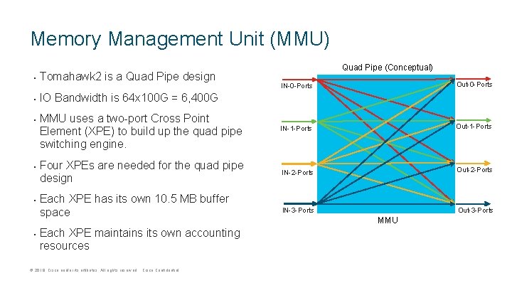
Memory Management Unit (MMU) • Tomahawk 2 is a Quad Pipe design • IO Bandwidth is 64 x 100 G = 6, 400 G • • Quad Pipe (Conceptual) IN-0 -Ports Out-0 -Ports MMU uses a two-port Cross Point Element (XPE) to build up the quad pipe switching engine. IN-1 -Ports Out-1 -Ports Four XPEs are needed for the quad pipe design IN-2 -Ports Out-2 -Ports IN-3 -Ports Out-3 -Ports Each XPE has its own 10. 5 MB buffer space Each XPE maintains its own accounting resources © 2019 Cisco and/or its affiliates. All rights reserved. Cisco Confidential MMU
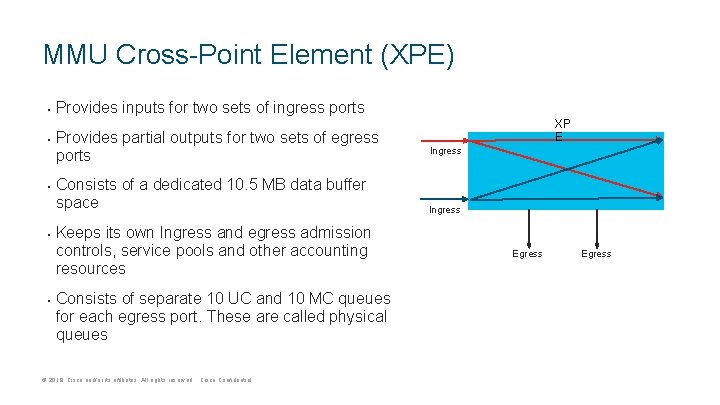
MMU Cross-Point Element (XPE) • • • Provides inputs for two sets of ingress ports Provides partial outputs for two sets of egress ports Consists of a dedicated 10. 5 MB data buffer space Keeps its own Ingress and egress admission controls, service pools and other accounting resources Consists of separate 10 UC and 10 MC queues for each egress port. These are called physical queues © 2019 Cisco and/or its affiliates. All rights reserved. Cisco Confidential XP E Ingress Egress
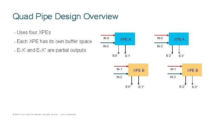
Quad Pipe Design Overview • Uses four XPEs • Each XPE has its own buffer space • E-X’ and E-X” are partial outputs IN-0 XPE A IN-3 E-0’ E-2’ E-1’ IN-1 XPE B IN-2 E-3’ IN-1 XPE B IN-2 E-0” © 2019 Cisco and/or its affiliates. All rights reserved. Cisco Confidential XPE A E-1” E-2” E-3”
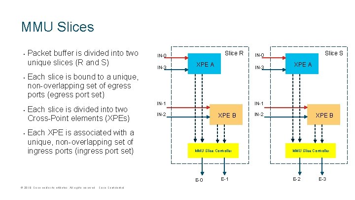
MMU Slices • • Packet buffer is divided into two unique slices (R and S) Slice R IN-0 IN-3 XPE A Slice S IN-0 IN-3 XPE A Each slice is bound to a unique, non-overlapping set of egress ports (egress port set) Each slice is divided into two Cross-Point elements (XPEs) Each XPE is associated with a unique, non-overlapping set of ingress ports (ingress port set) IN-1 IN-2 XPE B MMU Slice Controller E-0 © 2019 Cisco and/or its affiliates. All rights reserved. Cisco Confidential E-1 IN-2 XPE B MMU Slice Controller E-2 E-3
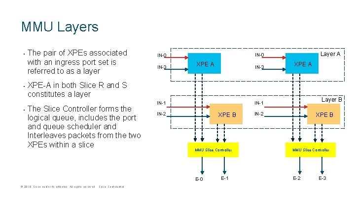
MMU Layers • • • The pair of XPEs associated with an ingress port set is referred to as a layer IN-3 Layer A IN-0 XPE A IN-3 XPE A XPE-A in both Slice R and S constitutes a layer The Slice Controller forms the logical queue, includes the port and queue scheduler and Interleaves packets from the two XPEs within a slice IN-2 XPE B MMU Slice Controller E-0 © 2019 Cisco and/or its affiliates. All rights reserved. Cisco Confidential Layer B IN-1 E-1 IN-2 XPE B MMU Slice Controller E-2 E-3
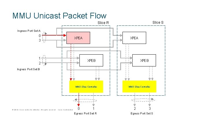
MMU Unicast Packet Flow Slice S Slice R Ingress Port Set A 0 3 XPE A 1 2 XPE A XPE B Ingress Port Set B MMU Slice Controller © 2019 Cisco and/or its affiliates. All rights reserved. Cisco Confidential 0 1 Egress Port Set R MMU Slice Controller 2 3 Egress Port Set S
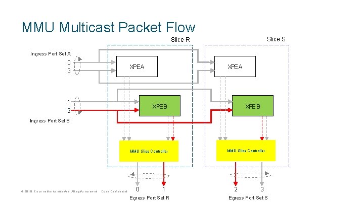
MMU Multicast Packet Flow Slice S Slice R Ingress Port Set A 0 3 XPE A 1 2 XPE A XPE B Ingress Port Set B MMU Slice Controller © 2019 Cisco and/or its affiliates. All rights reserved. Cisco Confidential 0 1 Egress Port Set R MMU Slice Controller 2 3 Egress Port Set S
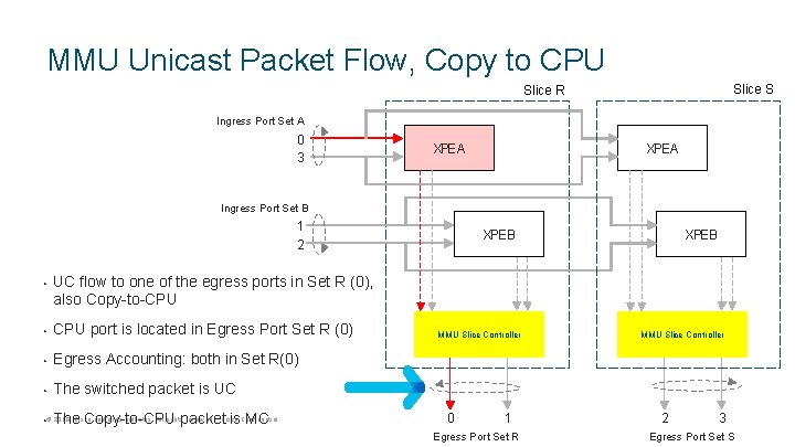
MMU Unicast Packet Flow, Copy to CPU Slice S Slice R Ingress Port Set A 0 3 XPE A Ingress Port Set B 1 2 • XPE B UC flow to one of the egress ports in Set R (0), also Copy-to-CPU • CPU port is located in Egress Port Set R (0) • Egress Accounting: both in Set R(0) • The switched packet is UC 2019 Cisco and/or its affiliates. All rightspacket reserved. Cisco • © The Copy-to-CPU is. Confidential MC MMU Slice Controller 0 1 Egress Port Set R MMU Slice Controller 2 3 Egress Port Set S
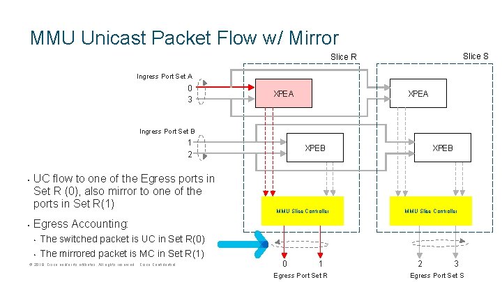
MMU Unicast Packet Flow w/ Mirror Slice S Slice R Ingress Port Set A 0 3 XPE A Ingress Port Set B 1 2 • • UC flow to one of the Egress ports in Set R (0), also mirror to one of the ports in Set R(1) XPE B MMU Slice Controller Egress Accounting: • • The switched packet is UC in Set R(0) The mirrored packet is MC in Set R(1) © 2019 Cisco and/or its affiliates. All rights reserved. Cisco Confidential 0 1 Egress Port Set R 2 3 Egress Port Set S
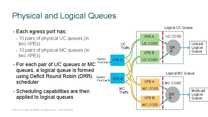
Physical and Logical Queues • Each egress port has: • • Logical UC Queue 10 pairs of physical UC queues (in two XPEs) 10 pairs of physical MC queues (in two XPEs) XPE A UC Traffic For each pair of UC queues or MC queues, a logical queue is formed using Deficit Round Robin (DRR) Ingress Port Set B scheduler Scheduling capabilities are then applied to logical queues UC COS 0 XPE B Ingress Port Set A XPE A DR R Unicast Logical Queue UC COS 0 Logical MC Queue XPE B MC Traffic XPE A MC COS 0 XPE B MC COS 0 © 2019 Cisco and/or its affiliates. All rights reserved. Cisco Confidential UC COS 0 DR R Multicast Logical Queue
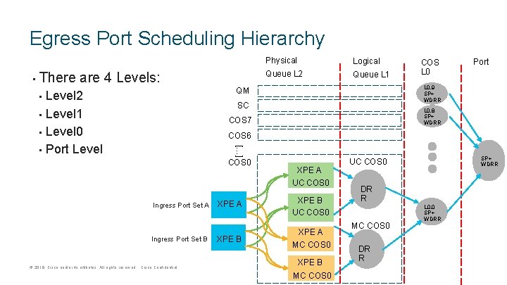
Egress Port Scheduling Hierarchy • There are 4 Levels: Physical Logical Queue L 2 Queue L 1 Level 2 • Level 1 • Level 0 • Port Level Port L 0. 9 SP+ WDRR QM • COS L 0 SC L 0. 8 SP+ WDRR COS 7 COS 6 […] COS 0 Ingress Port Set A Ingress Port Set B © 2019 Cisco and/or its affiliates. All rights reserved. Cisco Confidential XPE A UC COS 0 XPE A XPE B UC COS 0 XPE B XPE A MC COS 0 XPE B MC COS 0 SP+ WDRR UC COS 0 DR R MC COS 0 DR R L 0. 0 SP+ WDRR
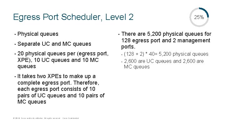
Egress Port Scheduler, Level 2 • Physical queues • Separate UC and MC queues • • 20 physical queues per (egress port, XPE), 10 UC queues and 10 MC queues It takes two XPEs to make up a complete egress port. Therefore, each egress port consists of 10 pairs of UC queues and 10 pairs of MC queues © 2019 Cisco and/or its affiliates. All rights reserved. Cisco Confidential • 25% There are 5, 200 physical queues for 128 egress port and 2 management ports. • • (128 + 2) * 40= 5, 200 physical queues 2, 600 are UC queues and 2, 600 are MC queues
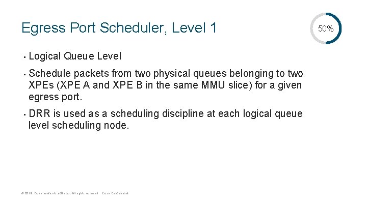
Egress Port Scheduler, Level 1 • • • Logical Queue Level Schedule packets from two physical queues belonging to two XPEs (XPE A and XPE B in the same MMU slice) for a given egress port. DRR is used as a scheduling discipline at each logical queue level scheduling node. © 2019 Cisco and/or its affiliates. All rights reserved. Cisco Confidential 50%
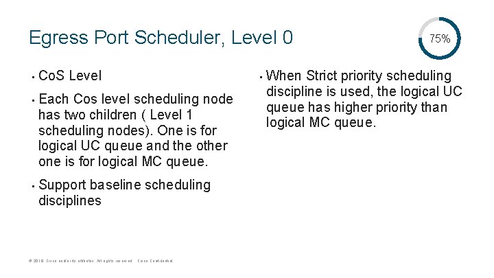
Egress Port Scheduler, Level 0 • • • Co. S Level Each Cos level scheduling node has two children ( Level 1 scheduling nodes). One is for logical UC queue and the other one is for logical MC queue. Support baseline scheduling disciplines © 2019 Cisco and/or its affiliates. All rights reserved. Cisco Confidential • 75% When Strict priority scheduling discipline is used, the logical UC queue has higher priority than logical MC queue.
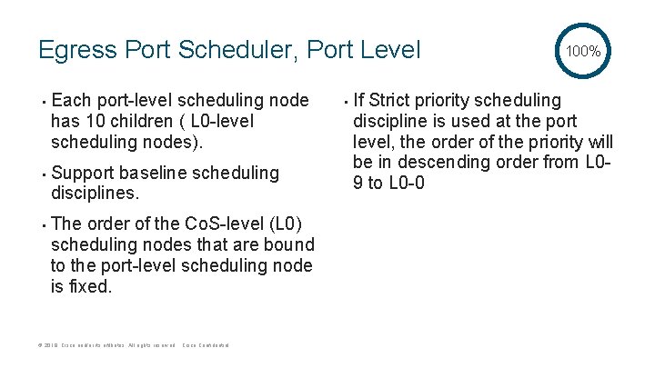
Egress Port Scheduler, Port Level • • • Each port-level scheduling node has 10 children ( L 0 -level scheduling nodes). Support baseline scheduling disciplines. The order of the Co. S-level (L 0) scheduling nodes that are bound to the port-level scheduling node is fixed. © 2019 Cisco and/or its affiliates. All rights reserved. Cisco Confidential • 100% If Strict priority scheduling discipline is used at the port level, the order of the priority will be in descending order from L 09 to L 0 -0
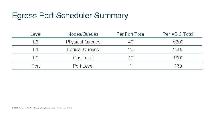
Egress Port Scheduler Summary Level Nodes/Queues Per Port Total Per ASIC Total L 2 Physical Queues 40 5200 L 1 Logical Queues 20 2600 L 0 Cos Level 10 1300 Port Level 1 130 © 2019 Cisco and/or its affiliates. All rights reserved. Cisco Confidential
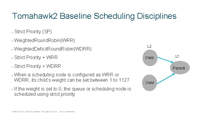
Tomahawk 2 Baseline Scheduling Disciplines • Strict Priority (SP) • Weighted. Round. Robin(WRR) • Weighted. Deficit. Round. Robin(WDRR) • Strict Priority + WRR • Strict Priority + WDRR • • When a scheduling node is configured as WRR or WDRR, its child’s weight can be set between 1 to 1127 If the weight is set to 0, the queue or scheduling node is scheduled using strict priority © 2019 Cisco and/or its affiliates. All rights reserved. Cisco Confidential L 2 Child L 1 Parent Child
Replication Queuing Engine (RQE) • • There is one RQE per XPE In each RQE there are 11 queues which supports 8 multicast class of service, two type of CPU traffic (High and Low) and SPAN. The RQE scheduling is only one level One RQUE scheduling schedule packet for replication among 11 RQE queues © 2019 Cisco and/or its affiliates. All rights reserved. Cisco Confidential
RQE Scheduler • • • RQE scheduling node has 11 children (RQE queues) The order of the RQE queues that are bound to the RQE scheduling node is fixed When the RQE scheduling node is configured to utilize a strict priorityscheduling discipline, the order of the priority will be in descending order from RQE queue 10 to RQE queue 0. © 2019 Cisco and/or its affiliates. All rights reserved. Cisco Confidential
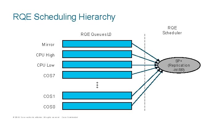
RQE Scheduling Hierarchy RQE Queues L 0 RQE Scheduler M irror CPU High CPU Low COS 7 COS 1 COS 0 © 2019 Cisco and/or its affiliates. All rights reserved. Cisco Confidential SP+ (Rep licat io n -W RR)
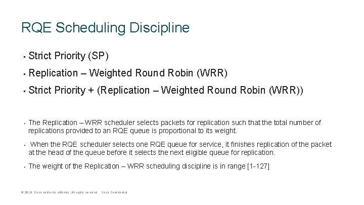
RQE Scheduling Discipline • Strict Priority (SP) • Replication – Weighted Round Robin (WRR) • Strict Priority + (Replication – Weighted Round Robin (WRR)) • • • The Replication – WRR scheduler selects packets for replication such that the total number of replications provided to an RQE queue is proportional to its weight. When the RQE scheduler selects one RQE queue for service, it finishes replication of the packet at the head of the queue before it selects the next eligible queue for replication. The weight of the Replication – WRR scheduling discipline is in range [1 -127] © 2019 Cisco and/or its affiliates. All rights reserved. Cisco Confidential
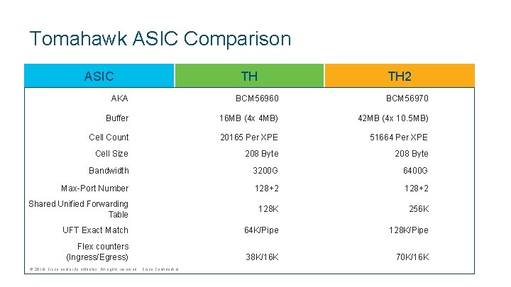
Tomahawk ASIC Comparison ASIC TH TH 2 AKA BCM 56960 BCM 56970 Buffer 16 MB (4 x 4 MB) 42 MB (4 x 10. 5 MB) Cell Count 20165 Per XPE 51664 Per XPE Cell Size 208 Byte Bandwidth 3200 G 6400 G Max-Port Number 128+2 Shared Unified Forwarding Table 128 K 256 K UFT Exact Match 64 K/Pipe 128 K/Pipe Flex counters (Ingress/Egress) 38 K/16 K 70 K/16 K © 2019 Cisco and/or its affiliates. All rights reserved. Cisco Confidential
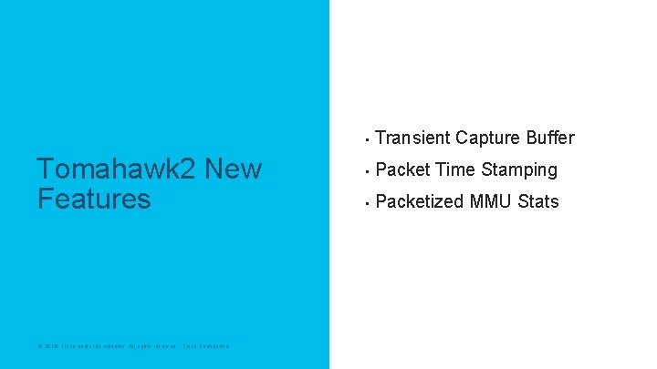
Tomahawk 2 New Features © 2019 Cisco and/or its affiliates. All rights reserved. Cisco Confidential • Transient Capture Buffer • Packet Time Stamping • Packetized MMU Stats
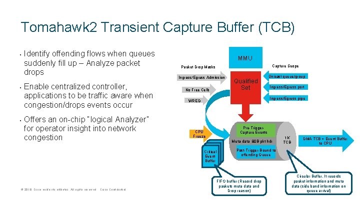
Tomahawk 2 Transient Capture Buffer (TCB) • • • Identify offending flows when queues suddenly fill up – Analyze packet drops Enable centralized controller, applications to be traffic aware when congestion/drops events occur Offers an on-chip “logical Analyzer” for operator insight into network congestion MMU Ingress/Egress Admission No Free Cells Qualified Set Unicast queue/group Ingress/Egress port Ingress/Egress pipe WRED CPU Freeze Pre-Trigger. Capture Events Meta-data 80 B pkt hdr Critical Event Buffer © 2019 Cisco and/or its affiliates. All rights reserved. Cisco Confidential Capture Scope Packet Drop Masks 1 K TCB DMA TCB + Event Buffer to CPU Post-Trigger-Bound to offending Queue FIFO buffer (Record drop packets meta data and Drop reason) Circular Buffer, It records packet information and meta data (side band information on queue arrival)
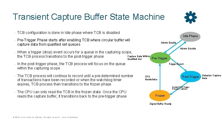
Transient Capture Buffer State Machine • • TCB configuration is done in Idle phase where TCB is disabled Idle Phase Pre-Trigger Phase starts after enabling TCB where circular buffer will capture data from qualified set queues Admin Enable Admin Disable • • When a trigger (drop) event occurs for a queue in the capturing scope, Capture Data Within the TCB process transitions to the post-trigger phase Pre-Trigger Qualified Set In the post-trigger phase, the TCB process will focus on the queue within the capturing scope The TCB process will continue to record until a pre-determined number of transactions have been recorded or when the watchdog timer expires, TCB process then transitions to the frozen phase The CPU can only read the TCB in the frozen state. Once the CPU reads the capture buffer, it transitions back to the pre-trigger phase Trigger Event CPU Handshake Enough Post-Trigger Records Captured Frozen Signal Buffer Ready © 2019 Cisco and/or its affiliates. All rights reserved. Cisco Confidential Post-Trigger Selective Capture Data
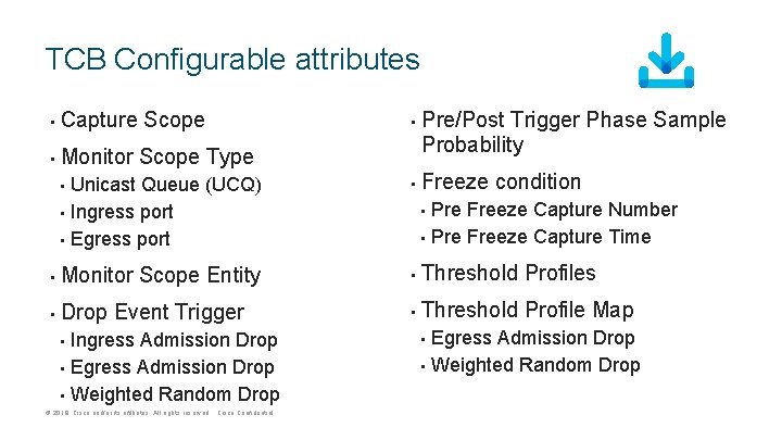
TCB Configurable attributes • Capture Scope • Monitor Scope Type • Pre/Post Trigger Phase Sample Probability Freeze condition Unicast Queue (UCQ) • Ingress port • Egress port • • Monitor Scope Entity • Threshold Profiles • Drop Event Trigger • Threshold Profile Map • Ingress Admission Drop • Egress Admission Drop • Weighted Random Drop • © 2019 Cisco and/or its affiliates. All rights reserved. Cisco Confidential Pre Freeze Capture Number • Pre Freeze Capture Time • Egress Admission Drop • Weighted Random Drop •
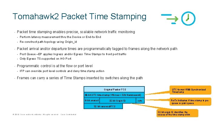
Tomahawk 2 Packet Time Stamping • • • Packet time stamping enables precise, scalable network traffic monitoring • Perform latency measurement thru the Device or End-to-End • Re-construct path topology using Origin_id Packet arrival and/or departure times are programmatically tagged to frames along the network path • Post Queue –EP applies Ingress and/or Egress Time Stamps to front port traffic • Only Egress TS supported on HG Port Programmatic control is at the flow or port level • • IFP can override port level controls and deny time stamp action Frames can carry a series of Time Stamps inserted by switches along the path UTC format 1588 Synchronized Timestamp Original Packet FCS 48 -bit UTC time-stamp (16 b sec + 32 b Nanosecond) 8 -bit unused 32 -bit Origin ID rx/tx Rx/Tx Indicates if time stamp is pre -queue or post-queue 32 -bit reserved/FCS © 2019 Cisco and/or its affiliates. All rights reserved. Cisco Confidential 32 -bit origin IS identifies the source of the time stamp shim
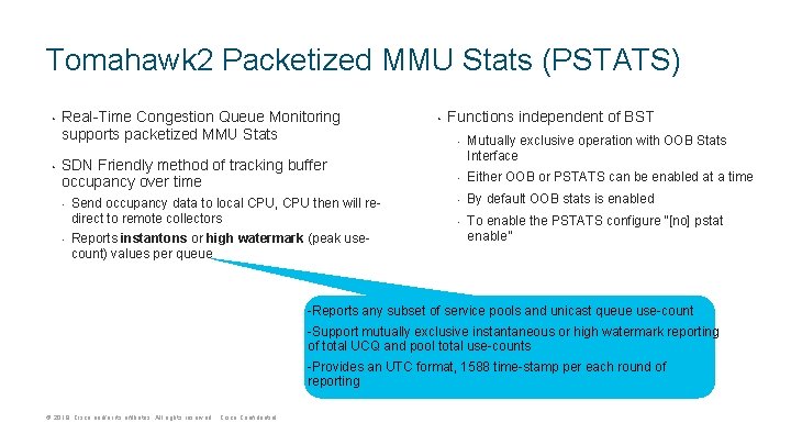
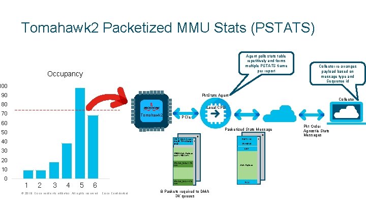
Tomahawk 2 Packetized MMU Stats (PSTATS) • • Real-Time Congestion Queue Monitoring supports packetized MMU Stats SDN Friendly method of tracking buffer occupancy over time • • Send occupancy data to local CPU, CPU then will redirect to remote collectors Reports instantons or high watermark (peak usecount) values per queue • Functions independent of BST • Mutually exclusive operation with OOB Stats Interface • Either OOB or PSTATS can be enabled at a time • By default OOB stats is enabled • To enable the PSTATS configure “[no] pstat enable” -Reports any subset of service pools and unicast queue use-count -Support mutually exclusive instantaneous or high watermark reporting of total UCQ and pool total use-counts -Provides an UTC format, 1588 time-stamp per each round of reporting © 2019 Cisco and/or its affiliates. All rights reserved. Cisco Confidential
Tomahawk 2 Packetized MMU Stats (PSTATS) Agent polls stats table repetitively and forms multiple PSTATS frame per report Occupancy 100 90 Pkt. Stats Agent 80 Collector Local CPU 70 Tomahawk 2 PCIe 60 Packetized Stats Message 50 8 14 B Pkt. Stats Header Src_ID, Time. Stamps, Seq# 40 1 8 ENET+. 1 Q IPv 4/IPv 6 UDP 30 1200 B Stats Payload carries 400 items 20 17 b Stat_Value + 7 b rsvd 10 0 Collector re-arranges payload based on message type and Sequence id 1 2 3 4 5 6 © 2019 Cisco and/or its affiliates. All rights reserved. Cisco Confidential 17 b Stat_Value + 7 b rsvd 8 Packets required to DMA 3 K queues Stats Payload FCS 1 Pkt Order Agnostic Stats Messages
Agenda © 2017 2019 Cisco and/or its affiliates. All rights reserved. Cisco Confidential 1 ASIC Architecture 2 Forwarding 3 Buffering 4 CT vs SF 5 Platform Overview
Tomahawk 2 Forwarding © 2019 Cisco and/or its affiliates. All rights reserved. Cisco Confidential
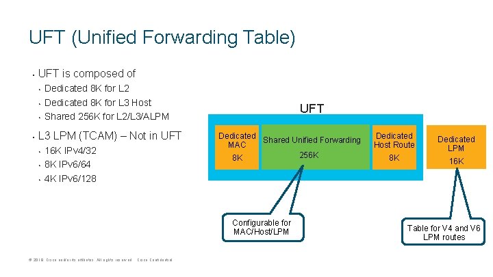
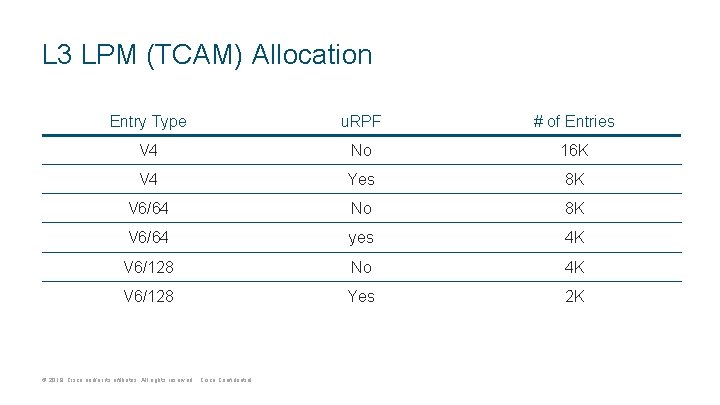
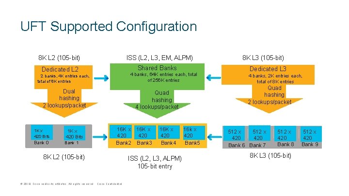
UFT (Unified Forwarding Table) • UFT is composed of • • Dedicated 8 K for L 2 Dedicated 8 K for L 3 Host Shared 256 K for L 2/L 3/ALPM L 3 LPM (TCAM) – Not in UFT • • • 16 K IPv 4/32 8 K IPv 6/64 4 K IPv 6/128 UFT Dedicated Shared Unified Forwarding MAC 256 K 8 K Configurable for MAC/Host/LPM © 2019 Cisco and/or its affiliates. All rights reserved. Cisco Confidential Dedicated Host Route Dedicated LPM 8 K 16 K Table for V 4 and V 6 LPM routes
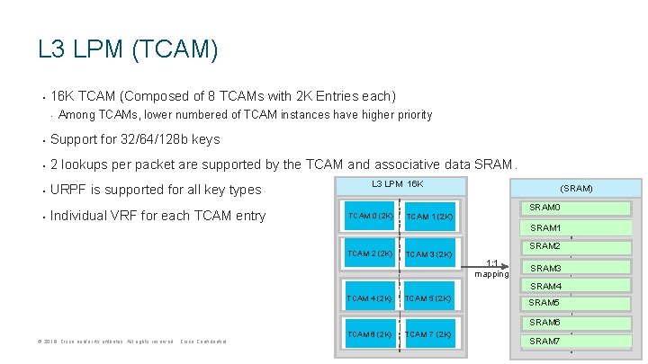
L 3 LPM (TCAM) • 16 K TCAM (Composed of 8 TCAMs with 2 K Entries each) • Among TCAMs, lower numbered of TCAM instances have higher priority • Support for 32/64/128 b keys • 2 lookups per packet are supported by the TCAM and associative data SRAM. • URPF is supported for all key types • Individual VRF for each TCAM entry L 3 LPM 16 K TCAM 0 (2 K) (SRAM) SRAM 0 TCAM 1 (2 K) SRAM 1 TCAM 2 (2 K) TCAM 3 (2 K) SRAM 2 1: 1 mapping SRAM 3 SRAM 4 TCAM 4 (2 K) TCAM 5 (2 K) TCAM 6 (2 K) TCAM 7 (2 K) SRAM 5 SRAM 6 © 2019 Cisco and/or its affiliates. All rights reserved. Cisco Confidential SRAM 7
L 3 LPM (TCAM) Allocation Entry Type u. RPF # of Entries V 4 No 16 K V 4 Yes 8 K V 6/64 No 8 K V 6/64 yes 4 K V 6/128 No 4 K V 6/128 Yes 2 K © 2019 Cisco and/or its affiliates. All rights reserved. Cisco Confidential
UFT Supported Configuration 8 K L 2 (105 -bit) ISS (L 2, L 3, EM, ALPM) Shared Banks Dedicated L 2 4 banks, 64 K entries each, total of 256 K entries 2 banks, 4 K entries each, total of 8 K entries Dual hashing 2 lookups/packet 1 K x 420 Bits Bank 0 1 K x 420 Bits Bank 1 8 K L 2 (105 -bit) © 2019 Cisco and/or its affiliates. All rights reserved. Cisco Confidential 16 K x 420 Bank 4 ISS (L 2, L 3, ALPM) 105 -bit entry Dedicated L 3 4 banks, 2 K entries each, total of 8 K entries Quad hashing 2 lookups/packet Quad hashing 4 lookups/packet 16 K x 420 Bank 2 Bank 3 8 K L 3 (105 -bit) 16 k x 420 Bank 5 512 x 420 Bank 6 Bank 7 512 x 420 Bank 8 8 K L 3 (105 -bit) 512 x 420 Bank 9
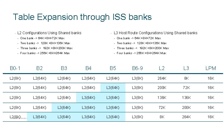
Table Expansion through ISS banks • L 2 Configurations Using Shared banks • L 3 Host Route Configurations Using Shared banks • One bank -> 64 K +8 K=72 K Max • Two banks -> 128 K +8 K=136 K Max • Three banks -> 192 K +8 K=200 K Max • Four banks -> 256 K +8 K=264 K Max B 0 -1 B 2 B 3 B 4 B 5 B 6 -9 L 2 L 3 LPM L 2(8 K) L 2(64 K) L 3(8 K) 264 K 8 K 16 K L 2(8 K) L 2(64 K) L 3(8 K) 200 K 72 K 16 K L 2(8 K) L 2(64 K) L 3(64 K) L 3(8 K) 136 K 16 K L 2(8 K) L 2(64 K) L 3(64 K) L 3(8 K) 72 K 200 K 16 K L 2(8 K) L 3(64 K) © 2019 Cisco and/or its affiliates. All rights reserved. Cisco Confidential L 3(64 K) L 3(8 K) 8 K 264 K 16 K
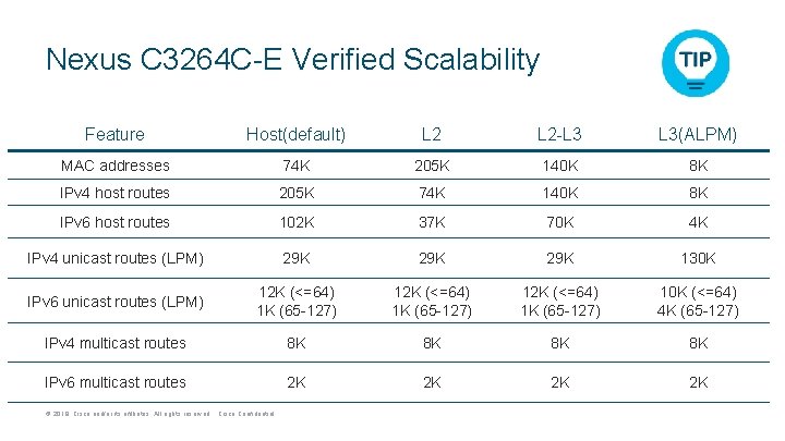
Nexus C 3264 C-E Verified Scalability Feature Host(default) L 2 -L 3 L 3(ALPM) MAC addresses 74 K 205 K 140 K 8 K IPv 4 host routes 205 K 74 K 140 K 8 K IPv 6 host routes 102 K 37 K 70 K 4 K IPv 4 unicast routes (LPM) 29 K 29 K 130 K IPv 6 unicast routes (LPM) 12 K (<=64) 1 K (65 -127) 10 K (<=64) 4 K (65 -127) IPv 4 multicast routes 8 K 8 K IPv 6 multicast routes 2 K 2 K © 2019 Cisco and/or its affiliates. All rights reserved. Cisco Confidential
Agenda © 2017 2019 Cisco and/or its affiliates. All rights reserved. Cisco Confidential 1 ASIC Architecture 2 Forwarding 3 Buffering 4 CT vs SF 5 Platform Overview
Tomahawk 2 Buffer Management © 2019 Cisco and/or its affiliates. All rights reserved. Cisco Confidential
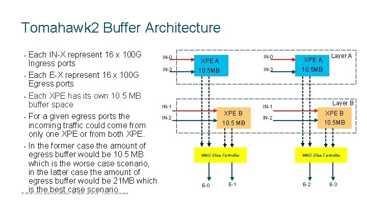
Tomahawk 2 Buffer Architecture • • • Each IN-X represent 16 x 100 G Ingress ports Each E-X represent 16 x 100 G Egress ports Each XPE has its own 10. 5 MB buffer space For a given egress ports the incoming traffic could come from only one XPE or from both XPE. In the former case the amount of egress buffer would be 10. 5 MB which is the worse case scenario, in the latter case the amount of egress buffer would be 21 MB which is the best case scenario © 2019 Cisco and/or its affiliates. All rights reserved. Cisco Confidential IN-0 IN-3 IN-0 XPE A IN-3 10. 5 MB XPE A 10. 5 MB Layer B IN-1 XPE B IN-2 10. 5 MB MMU Slice Controller E-0 E-1 Layer A XPE B IN-2 10. 5 MB MMU Slice Controller E-2 E-3
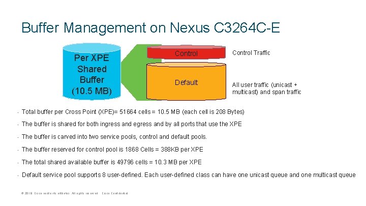
Buffer Management on Nexus C 3264 C-E Per XPE Shared Buffer (10. 5 MB) Control Traffic Default All user traffic (unicast + multicast) and span traffic • Total buffer per Cross Point (XPE)= 51664 cells = 10. 5 MB (each cell is 208 Bytes) • The buffer is shared for both ingress and egress and by all ports that use the XPE • The buffer is carved into two service pools, control and default pools. • The buffer reserved for control pool is 1868 Cells = 388 KB per XPE • The total shared available buffer is 49796 cells = 10. 3 MB per XPE • Default service pool supports 8 user-defined. Each user-defined class can have one unicast queue and one multicast queue © 2019 Cisco and/or its affiliates. All rights reserved. Cisco Confidential
Accounting Basics • • • Tomahawk 2 uses shared buffer architecture (10. 5 MB) per Cross Points (XPE) Packet is stored only once in the buffer, but accounted twice (ingress, egress) When a packet enters through a port, ingress accounting information for that ingress port increments © 2019 Cisco and/or its affiliates. All rights reserved. Cisco Confidential • • When a packet gets queued on an egress port, egress accounting information for that egress port increments When a packet egresses the chip, both ingress/egress accounting decrements
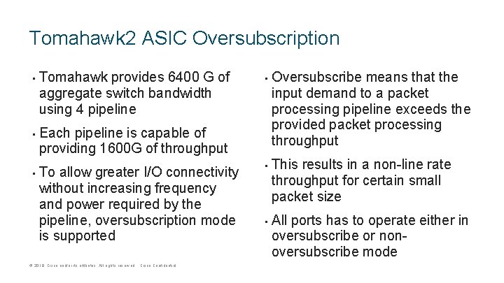
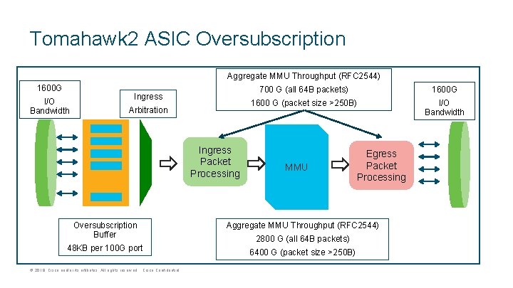
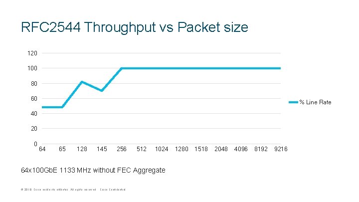
Tomahawk 2 ASIC Oversubscription • • • Tomahawk provides 6400 G of aggregate switch bandwidth using 4 pipeline • Each pipeline is capable of providing 1600 G of throughput To allow greater I/O connectivity without increasing frequency and power required by the pipeline, oversubscription mode is supported © 2019 Cisco and/or its affiliates. All rights reserved. Cisco Confidential • • Oversubscribe means that the input demand to a packet processing pipeline exceeds the provided packet processing throughput This results in a non-line rate throughput for certain small packet size All ports has to operate either in oversubscribe or nonoversubscribe mode
Tomahawk 2 ASIC Oversubscription Aggregate MMU Throughput (RFC 2544) 1600 G I/O Bandwidth Ingress Arbitration Ingress Packet Processing 700 G (all 64 B packets) 1600 G 1600 G (packet size >250 B) I/O Bandwidth MMU Egress Packet Processing Oversubscription Buffer Aggregate MMU Throughput (RFC 2544) 48 KB per 100 G port 6400 G (packet size >250 B) © 2019 Cisco and/or its affiliates. All rights reserved. Cisco Confidential 2800 G (all 64 B packets)
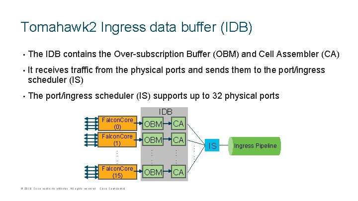
Tomahawk 2 Ingress data buffer (IDB) • • • The IDB contains the Over-subscription Buffer (OBM) and Cell Assembler (CA) It receives traffic from the physical ports and sends them to the port/ingress scheduler (IS) The port/ingress scheduler (IS) supports up to 32 physical ports IDB OBM CA Falcon. Core (1) OBM CA …… © 2019 Cisco and/or its affiliates. All rights reserved. Cisco Confidential …… …… Falcon. Core (15) OBM CA …… Falcon. Core (0) IS Ingress Pipeline
RFC 2544 Throughput vs Packet size 120 100 80 60 % Line Rate 40 20 0 64 65 128 145 256 512 1024 64 x 100 Gb. E 1133 MHz without FEC Aggregate © 2019 Cisco and/or its affiliates. All rights reserved. Cisco Confidential 1280 1518 2048 4096 8192 9216
Agenda © 2017 2019 Cisco and/or its affiliates. All rights reserved. Cisco Confidential 1 ASIC Architecture 2 Forwarding 3 Buffering 4 CT vs SF 5 Platform Overview
Tomahawk 2 Cut-Through Mode © 2019 Cisco and/or its affiliates. All rights reserved. Cisco Confidential
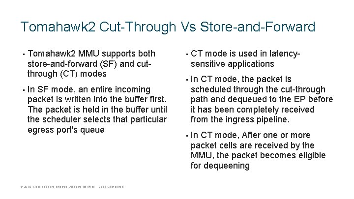
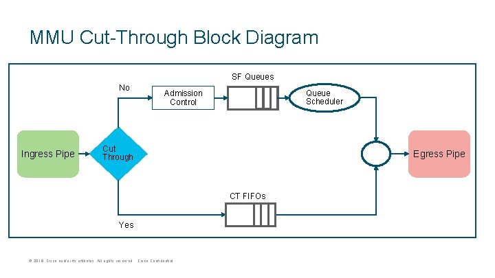
Tomahawk 2 Cut-Through Vs Store-and-Forward • • Tomahawk 2 MMU supports both store-and-forward (SF) and cutthrough (CT) modes In SF mode, an entire incoming packet is written into the buffer first. The packet is held in the buffer until the scheduler selects that particular egress port's queue © 2019 Cisco and/or its affiliates. All rights reserved. Cisco Confidential • • • CT mode is used in latencysensitive applications In CT mode, the packet is scheduled through the cut-through path and dequeued to the EP before it has been completely received from the ingress pipeline. In CT mode, After one or more packet cells are received by the MMU, the packet becomes eligible for dequeening
MMU Cut-Through Block Diagram SF Queues No Ingress Pipe Queue Scheduler Admission Control Cut Through Egress Pipe CT FIFOs Yes © 2019 Cisco and/or its affiliates. All rights reserved. Cisco Confidential
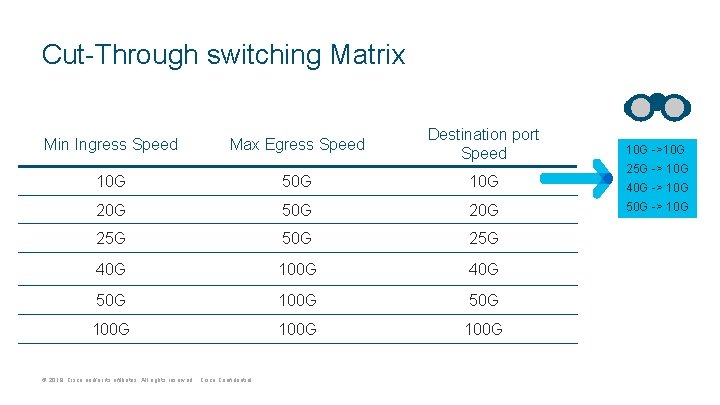
Cut-Through switching Matrix Min Ingress Speed Max Egress Speed Destination port Speed 10 G ->10 G 50 G 10 G 40 G -> 10 G 20 G 50 G 25 G 40 G 100 G 40 G 50 G 100 G © 2019 Cisco and/or its affiliates. All rights reserved. Cisco Confidential 25 G -> 10 G 50 G -> 10 G
Agenda © 2017 2019 Cisco and/or its affiliates. All rights reserved. Cisco Confidential 1 ASIC Architecture 2 Forwarding 3 Buffering 4 CT vs SF 5 Platform Overview
N 3 K-C 3264 C-E Platform Overview © 2019 Cisco and/or its affiliates. All rights reserved. Cisco Confidential
N 3 K-C 3264 C-E © 2019 Cisco and/or its affiliates. All rights reserved. Cisco Confidential • Switch Overview • System Characteristics • Power Characteristics • Switch Architecture • ASIC Port-map • Breakout Port-mode • Performance
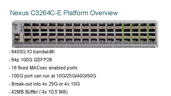
Nexus C 3264 C-E Platform Overview • 6400 G IO bandwidth • 64 p 100 G QSFP 28 • 16 fixed MACsec enabled ports • 100 G port can run at 10 G/25 G/40 G/50 G • Break-out into 4 x 25 G or 4 x 10 G © 2019 Cisco and/or its affiliates. All rights reserved. Cisco Confidential • 42 MB Buffer ( 4 x 10. 5 MB)
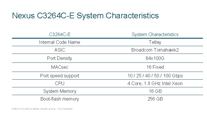
Nexus C 3264 C-E System Characteristics Internal Code Name Tetley ASIC Broadcom Tomahawk 2 Port Density 64 x 100 G MACsec 16 Fixed Port speed support 10 / 25 / 40 / 50 / 100 Gbps CPU 4 Core, 1. 8 GHz Intel Xeon System Memory 16 GB Boot-flash memory 256 GB © 2019 Cisco and/or its affiliates. All rights reserved. Cisco Confidential
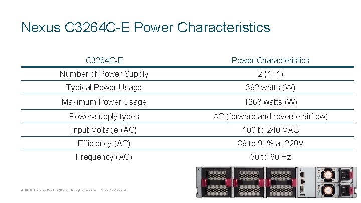
Nexus C 3264 C-E Power Characteristics Number of Power Supply 2 (1+1) Typical Power Usage 392 watts (W) Maximum Power Usage 1263 watts (W) Power-supply types AC (forward and reverse airflow) Input Voltage (AC) 100 to 240 VAC Efficiency (AC) 89 to 91% at 220 V Frequency (AC) 50 to 60 Hz © 2019 Cisco and/or its affiliates. All rights reserved. Cisco Confidential
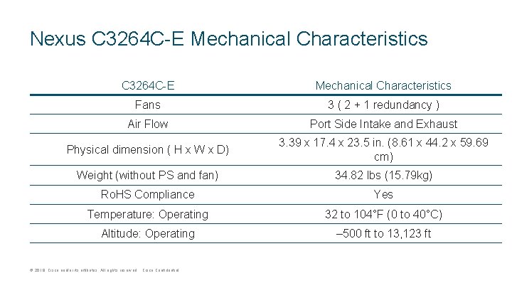
Nexus C 3264 C-E Mechanical Characteristics Fans 3 ( 2 + 1 redundancy ) Air Flow Port Side Intake and Exhaust Physical dimension ( H x W x D) 3. 39 x 17. 4 x 23. 5 in. (8. 61 x 44. 2 x 59. 69 cm) Weight (without PS and fan) 34. 82 lbs (15. 79 kg) Ro. HS Compliance Yes Temperature: Operating 32 to 104°F (0 to 40°C) Altitude: Operating – 500 ft to 13, 123 ft © 2019 Cisco and/or its affiliates. All rights reserved. Cisco Confidential
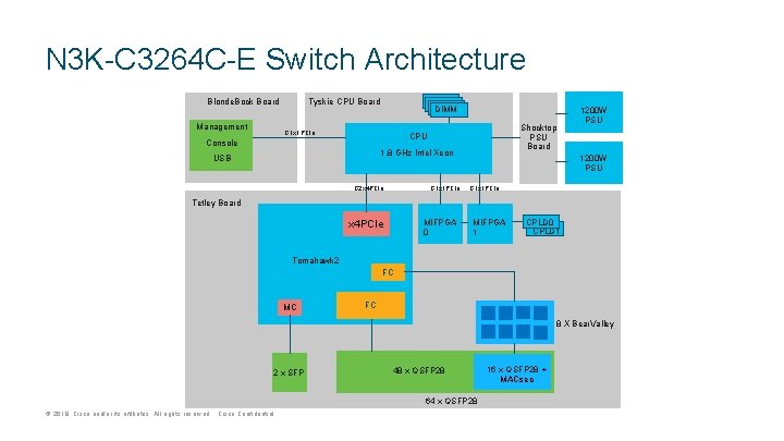
N 3 K-C 3264 C-E Switch Architecture Tyskie CPU Board Blonde. Bock Board Management DIMM G 1 x 1 PCIe Shocktop PSU Board CPU Console 1. 8 GHz Intel Xeon USB G 1 x 1 PCIe G 2 x 4 PCIe 1200 W PSU G 1 x 1 PCIe Tetley Board MIFPGA 0 x 4 PCIe MIFPGA 1 CPLD 0 CPLD 1 Tomahawk 2 FC MC FC 8 X Bear. Valley 2 x SFP 48 x QSFP 28 64 x QSFP 28 © 2019 Cisco and/or its affiliates. All rights reserved. Cisco Confidential 16 x QSFP 28 + MACsec
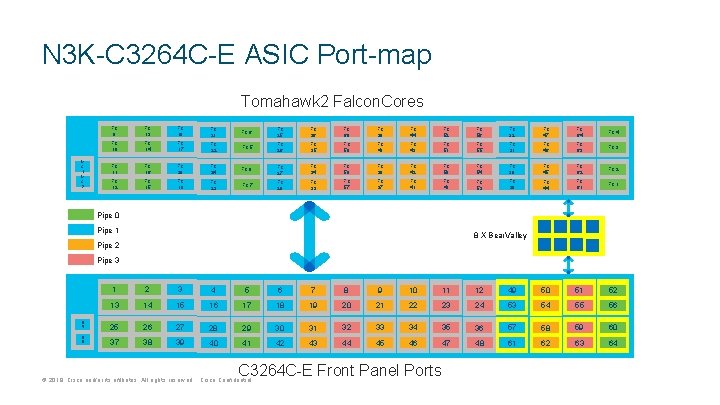
N 3 K-C 3264 C-E ASIC Port-map Tomahawk 2 Falcon. Cores M C 1 M C 2 FC 9 FC 13 FC 18 FC 21 FC 10 FC 14 FC 17 FC 11 FC 16 FC 12 FC 15 FC 6 FC 25 FC 36 FC 60 FC 39 FC 44 FC 52 FC 56 FC 32 FC 47 FC 64 FC 22 FC 5 FC 26 FC 35 FC 59 FC 40 FC 43 FC 51 FC 55 FC 31 FC 46 FC 63 FC 20 FC 24 FC 8 FC 27 FC 34 FC 58 FC 38 FC 42 FC 50 FC 54 FC 30 FC 45 FC 62 FC 19 FC 23 FC 7 FC 28 FC 33 FC 57 FC 37 FC 41 FC 49 FC 53 FC 29 FC 44 FC 61 FC 1 Pipe 0 Pipe 1 8 X Bear. Valley Pipe 2 Pipe 3 6 5 6 6 1 2 3 4 5 6 7 8 9 10 11 12 49 50 51 52 13 14 15 16 17 18 19 20 21 22 23 24 53 54 55 56 25 26 27 28 29 30 31 32 33 34 35 36 57 58 59 60 37 38 39 40 41 42 43 44 45 46 47 48 61 62 63 64 C 3264 C-E Front Panel Ports © 2019 Cisco and/or its affiliates. All rights reserved. Cisco Confidential
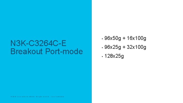
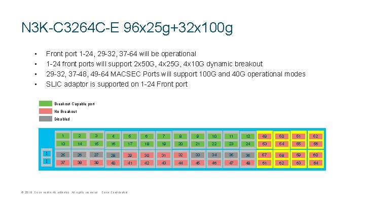
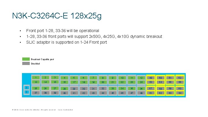
N 3 K-C 3264 C-E Breakout Port-mode © 2019 Cisco and/or its affiliates. All rights reserved. Cisco Confidential • 96 x 50 g + 16 x 100 g • 96 x 25 g + 32 x 100 g • 128 x 25 g
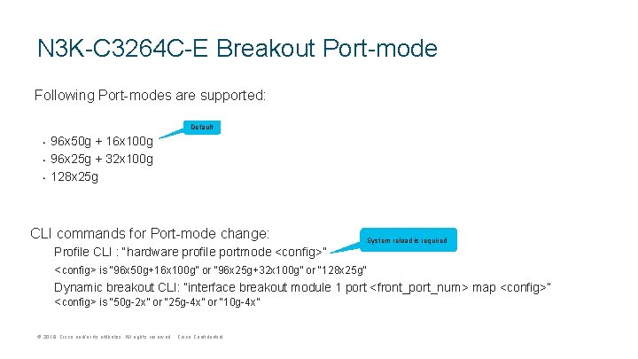
N 3 K-C 3264 C-E Breakout Port-mode Following Port-modes are supported: Default • • • 96 x 50 g + 16 x 100 g 96 x 25 g + 32 x 100 g 128 x 25 g CLI commands for Port-mode change: System reload is required Profile CLI : “hardware profile portmode <config>” <config> is “ 96 x 50 g+16 x 100 g” or “ 96 x 25 g+32 x 100 g” or “ 128 x 25 g” Dynamic breakout CLI: “interface breakout module 1 port <front_port_num> map <config>” <config> is “ 50 g-2 x” or “ 25 g-4 x” or “ 10 g-4 x” © 2019 Cisco and/or its affiliates. All rights reserved. Cisco Confidential
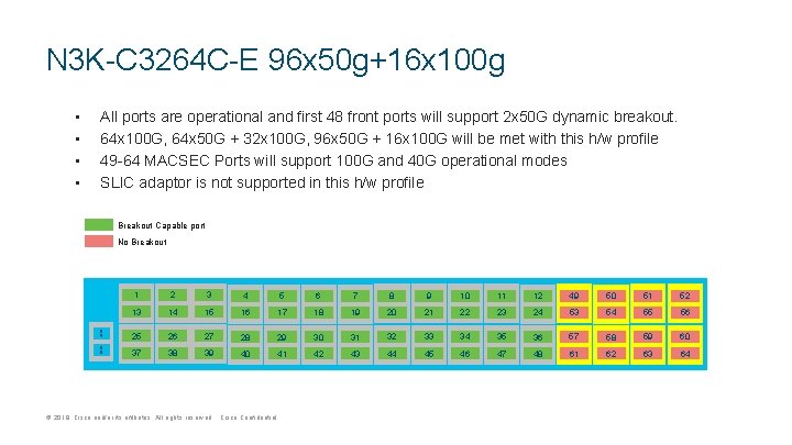
N 3 K-C 3264 C-E 96 x 50 g+16 x 100 g • • All ports are operational and first 48 front ports will support 2 x 50 G dynamic breakout. 64 x 100 G, 64 x 50 G + 32 x 100 G, 96 x 50 G + 16 x 100 G will be met with this h/w profile 49 -64 MACSEC Ports will support 100 G and 40 G operational modes SLIC adaptor is not supported in this h/w profile Breakout Capable port No Breakout 6 5 6 6 1 2 3 4 5 6 7 8 9 10 11 12 49 50 51 52 13 14 15 16 17 18 19 20 21 22 23 24 53 54 55 56 25 26 27 28 29 30 31 32 33 34 35 36 57 58 59 60 37 38 39 40 41 42 43 44 45 46 47 48 61 62 63 64 © 2019 Cisco and/or its affiliates. All rights reserved. Cisco Confidential
N 3 K-C 3264 C-E 96 x 25 g+32 x 100 g • • Front port 1 -24, 29 -32, 37 -64 will be operational 1 -24 front ports will support 2 x 50 G, 4 x 25 G, 4 x 10 G dynamic breakout 29 -32, 37 -48, 49 -64 MACSEC Ports will support 100 G and 40 G operational modes SLIC adaptor is supported on 1 -24 Front port Breakout Capable port No Breakout Disabled 6 5 6 6 1 2 3 4 5 6 7 8 9 10 11 12 49 50 51 52 13 14 15 16 17 18 19 20 21 22 23 24 53 54 55 56 25 26 27 28 29 30 31 32 33 34 35 36 57 58 59 60 37 38 39 40 41 42 43 44 45 46 47 48 61 62 63 64 © 2019 Cisco and/or its affiliates. All rights reserved. Cisco Confidential
N 3 K-C 3264 C-E 128 x 25 g • • • Front port 1 -28, 33 -36 will be operational 1 -28, 33 -36 front ports will support 2 x 50 G, 4 x 25 G, 4 x 10 G dynamic breakout SLIC adaptor is supported on 1 -24 Front port Breakout Capable port Disabled 6 5 6 6 1 2 3 4 5 6 7 8 9 10 11 12 49 50 51 52 13 14 15 16 17 18 19 20 21 22 23 24 53 54 55 56 25 26 27 28 29 30 31 32 33 34 35 36 57 58 59 60 37 38 39 40 41 42 43 44 45 46 47 48 61 62 63 64 © 2019 Cisco and/or its affiliates. All rights reserved. Cisco Confidential
N 3 K-C 3264 C-E Performance © 2019 Cisco and/or its affiliates. All rights reserved. Cisco Confidential • 64 x 100 g • 64 x 40 g
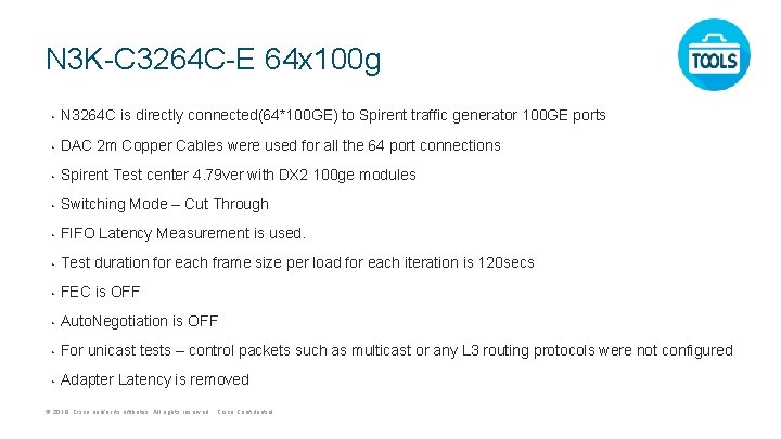
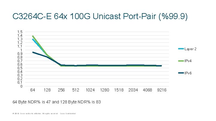
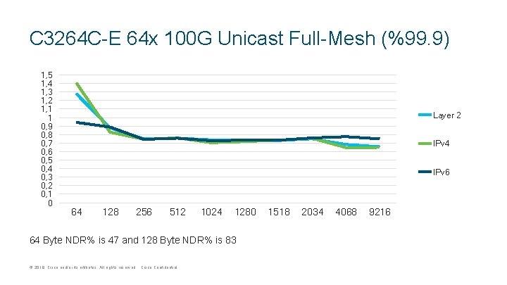
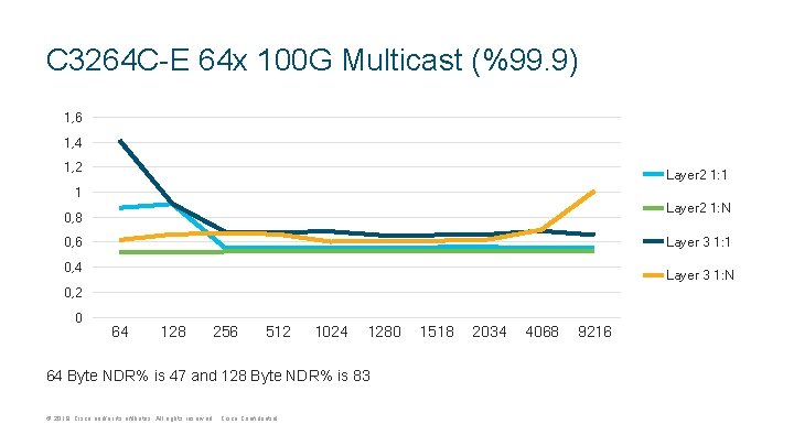
N 3 K-C 3264 C-E 64 x 100 g • N 3264 C is directly connected(64*100 GE) to Spirent traffic generator 100 GE ports • DAC 2 m Copper Cables were used for all the 64 port connections • Spirent Test center 4. 79 ver with DX 2 100 ge modules • Switching Mode – Cut Through • FIFO Latency Measurement is used. • Test duration for each frame size per load for each iteration is 120 secs • FEC is OFF • Auto. Negotiation is OFF • For unicast tests – control packets such as multicast or any L 3 routing protocols were not configured • Adapter Latency is removed © 2019 Cisco and/or its affiliates. All rights reserved. Cisco Confidential
C 3264 C-E 64 x 100 G Unicast Port-Pair (%99. 9) 1, 5 1, 4 1, 3 1, 2 1, 1 1 0, 9 0, 8 0, 7 0, 6 0, 5 0, 4 0, 3 0, 2 0, 1 0 Layer 2 IPv 4 IPv 6 64 128 256 512 1024 1280 64 Byte NDR% is 47 and 128 Byte NDR% is 83 © 2019 Cisco and/or its affiliates. All rights reserved. Cisco Confidential 1518 2034 4068 9216
C 3264 C-E 64 x 100 G Unicast Full-Mesh (%99. 9) 1, 5 1, 4 1, 3 1, 2 1, 1 1 0, 9 0, 8 0, 7 0, 6 0, 5 0, 4 0, 3 0, 2 0, 1 0 Layer 2 IPv 4 IPv 6 64 128 256 512 1024 1280 64 Byte NDR% is 47 and 128 Byte NDR% is 83 © 2019 Cisco and/or its affiliates. All rights reserved. Cisco Confidential 1518 2034 4068 9216
C 3264 C-E 64 x 100 G Multicast (%99. 9) 1, 6 1, 4 1, 2 Layer 2 1: 1 1 Layer 2 1: N 0, 8 Layer 3 1: 1 0, 6 0, 4 Layer 3 1: N 0, 2 0 64 128 256 512 1024 1280 64 Byte NDR% is 47 and 128 Byte NDR% is 83 © 2019 Cisco and/or its affiliates. All rights reserved. Cisco Confidential 1518 2034 4068 9216
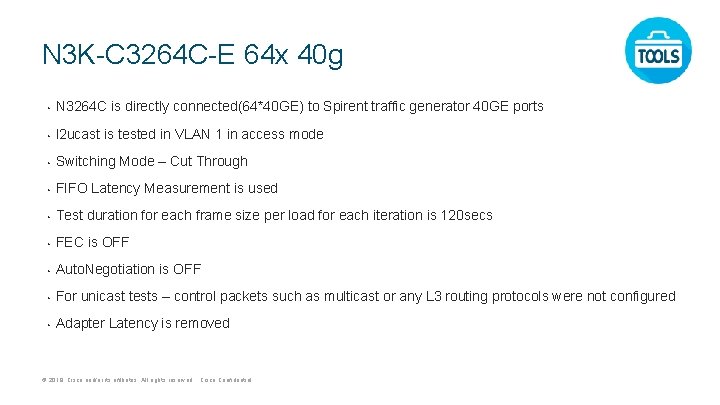
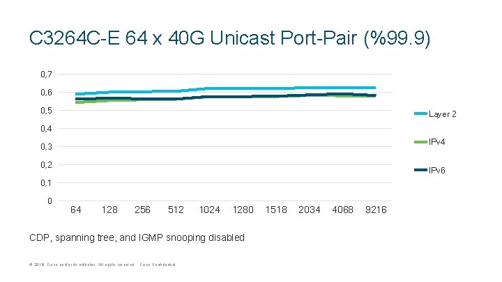
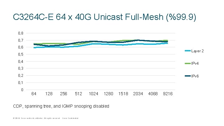
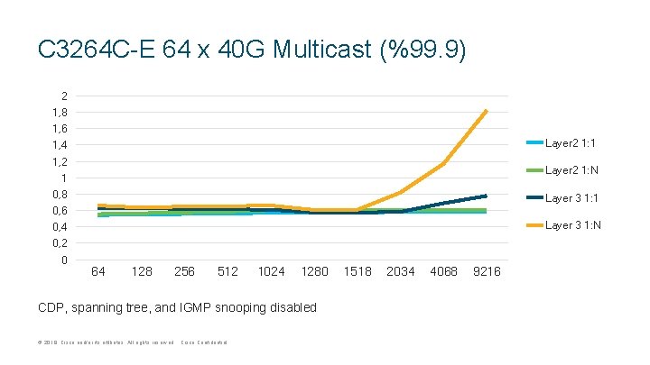
N 3 K-C 3264 C-E 64 x 40 g • N 3264 C is directly connected(64*40 GE) to Spirent traffic generator 40 GE ports • l 2 ucast is tested in VLAN 1 in access mode • Switching Mode – Cut Through • FIFO Latency Measurement is used • Test duration for each frame size per load for each iteration is 120 secs • FEC is OFF • Auto. Negotiation is OFF • For unicast tests – control packets such as multicast or any L 3 routing protocols were not configured • Adapter Latency is removed © 2019 Cisco and/or its affiliates. All rights reserved. Cisco Confidential
C 3264 C-E 64 x 40 G Unicast Port-Pair (%99. 9) 0, 7 0, 6 0, 5 Layer 2 0, 4 IPv 4 0, 3 0, 2 IPv 6 0, 1 0 64 128 256 512 1024 1280 CDP, spanning tree, and IGMP snooping disabled © 2019 Cisco and/or its affiliates. All rights reserved. Cisco Confidential 1518 2034 4068 9216
C 3264 C-E 64 x 40 G Unicast Full-Mesh (%99. 9) 0, 8 0, 7 0, 6 Layer 2 0, 5 0, 4 IPv 4 0, 3 0, 2 IPv 6 0, 1 0 64 128 256 512 1024 1280 CDP, spanning tree, and IGMP snooping disabled © 2019 Cisco and/or its affiliates. All rights reserved. Cisco Confidential 1518 2034 4068 9216
C 3264 C-E 64 x 40 G Multicast (%99. 9) 2 1, 8 1, 6 Layer 2 1: 1 1, 4 1, 2 Layer 2 1: N 1 0, 8 Layer 3 1: 1 0, 6 Layer 3 1: N 0, 4 0, 2 0 64 128 256 512 1024 1280 CDP, spanning tree, and IGMP snooping disabled © 2019 Cisco and/or its affiliates. All rights reserved. Cisco Confidential 1518 2034 4068 9216
Agenda © 2017 2019 Cisco and/or its affiliates. All rights reserved. Cisco Confidential 1 ASIC Architecture 2 Forwarding 3 Buffering 4 CT vs SF 5 Platform Overview