Todays Agenda MIPS ISA Microcomputer without Interlocked Pipeline


![Load/Store Instructions n n Load and store instructions Example: C code: A[8] = h](https://slidetodoc.com/presentation_image_h2/7bf2f8c155e19b7cced0f991c9688a27/image-12.jpg "Load/Store Instructions n n Load and store instructions Example: C code: A[8] = h")


 èShift Logical Right")


 n n MIPS unconditional branch instructions: j Label Example: if")

 e. g.")


")


 n Example C code – recursive factorial subroutine: int main() { int")
 Translated MIPS assembly: n . text. globl main slti $t 0, $a")


- Slides: 55
Today’s Agenda MIPS ISA Microcomputer without Interlocked Pipeline Stages !
We are going to learn n MIPS Instruction Set n n n Register Set Memory Organization n Types of Instructions Big Endian Vs Little Endian Instruction formats Design Principles
Instructions: Overview n n n Language of the machine More primitive than higher level languages, e. g. , no sophisticated control flow such as while or for loops Very restrictive n e. g. , MIPS arithmetic instructions We’ll be working with the MIPS instruction set architecture n inspired most architectures developed since the 80's n used by NEC, Nintendo, Silicon Graphics, Sony n the name is not related to millions of instructions per second ! n it stands for microcomputer without interlocked pipeline stages ! Design goals: maximize performance and minimize cost and reduce design time
Types of Instructions n Arithmetic Instructions n n Use only register operand Data Transfer Instructions Logical Instructions Branch Instructions n Conditional/Unconditional jump instructions
MIPS Arithmetic n All MIPS arithmetic instructions have 3 operands Operand order is fixed (e. g. , destination first) n Example: n C code: A = B + C MIPS code: add $s 0, $s 1, $s 2 compiler’s job to associate variables with registers
MIPS Arithmetic n Design Principle 1: simplicity favors regularity. Translation: Regular instructions makes the hardware simple! n n n Simpler hardware reduces design time and manufacturing cost. Of course this complicates some things. . . C code: A = B + C + D; E = F - A; MIPS code (arithmetic): add $t 0, $s 1, $s 2 add $s 0, $t 0, $s 3 sub $s 4, $s 5, $s 0 Allowing variable number of operands would simplify the assembly code but complicate the hardware. Performance penalty: high-level code translates to denser machine code.
MIPS Arithmetic n Operands must be in registers – only 32 registers provided (which require 5 bits to select one register). Reason for small number of registers: n Design Principle 2: smaller is faster. Why? n Electronic signals have to travel further on a physically larger chip increasing clock cycle time. n Smaller is also cheaper!
Registers vs. Memory n Arithmetic instructions operands must be in registers n MIPS has 32 registers n Compiler associates variables with registers What about programs with lots of variables (arrays, etc. )? Use memory, load/store operations to transfer data from memory to register n MIPS is a load/store architecture n Control Input Memory Datapath Processor Output I/O
Memory Organization n Viewed as a large single-dimension array with access by address A memory address is an index into the memory array Byte addressing means that the index points to a byte of memory, and that the unit of memory accessed by a load/store is a byte 0 1 8 bits of data 2 8 bits of data 3 4 5 6 8 bits of data . . . 8 bits of data
Memory Organization n Bytes are load/store units, but most data items use larger words For MIPS, a word is 32 bits or 4 bytes. 0 32 bits of data n 4 8 12 32 bits of data Registers correspondingly hold 32 bits of data . . . n n 232 bytes with byte addresses from 0 to 232 -1 230 words with byte addresses 0, 4, 8, . . . 232 -4 n i. e. , words are aligned n what are the least 2 significant bits of a word address?
Load/Store Instructions n n Load and store instructions Example: C code: A[8] = h + A[8]; MIPS code (load): (arithmetic): (store): n n value offset address lw $t 0, 32($s 3) add $t 0, $s 2, $t 0 sw $t 0, 32($s 3) Load word has destination first, store has destination last Remember MIPS arithmetic operands are registers, not memory locations n therefore, words must first be moved from memory to registers using loads before they can be operated on; then result can be stored back to memory
Memory Organization: Big/Little Endian Byte Order Bytes in a word can be numbered in two ways: Big-endian Memory Little-endian Memory Bit 0 Bit 31 n byte 0 at the leftmost (most significant) to byte 3 at the rightmost (least significant), called big-endian 0 1 2 3 byte 3 at the leftmost (most significant) to byte 0 at the rightmost (least significant), called little-endian 3 2 1 0 Bit 31 n Bit 0 n Byte 0 Byte 1 Byte 2 Byte 3 Word 0 Byte 3 Byte 2 Byte 1 Byte 0 Word 0 Byte 4 Byte 5 Byte 6 Byte 7 Word 1 Byte 7 Byte 6 Byte 5 Byte 4 Word 1
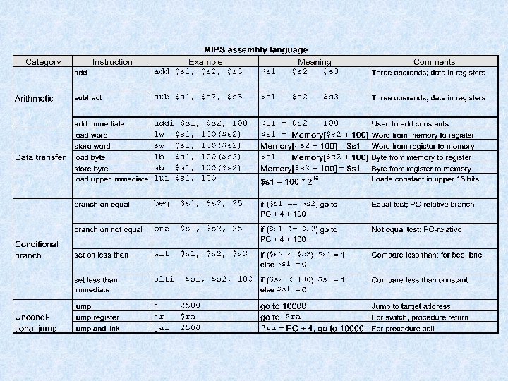
So far we’ve learned: n MIPS n n n loading words but addressing bytes arithmetic on registers only Instruction Meaning add $s 1, $s 2, $s 3 sub $s 1, $s 2, $s 3 lw $s 1, 100($s 2) sw $s 1, 100($s 2) $s 1 = $s 2 + $s 3 $s 1 = $s 2 – $s 3 $s 1 = Memory[$s 2+100]= $s 1
Machine Language n Instructions, like registers and words of data, are also 32 bits long n Example: add $t 0, $s 1, $s 2 n n registers are numbered, e. g. , $t 0 is 8, $s 1 is 17, $s 2 is 18 Instruction Format R-type (“R” for a. Rithmetic): 000000 10001 10010 01000 00000 op opcode – operation 6 bits rs first register source operand 5 bits rt rd shamt 100000 funct second register source operand register shift destin- amount ation operand function field selects variant of operation 5 bits 6 bits 5 bits
MIPS Encoding: R-Type 31 26 25 opcode 21 20 rs 16 15 rt 11 10 rd 6 5 shamt 0 funct rd rt add $4, $3, $2 rs 31 26 25 21 20 16 15 11 10 6 5 0 0 0 0 0 1 1 0 0 0 0 1 0 0 0 opcode rs rt rd shamt funct 0 0 0 0 0 1 1 0 0 0 0 1 0 0 0 Encoding = 0 x 00622020 17
Machine Language n Consider the load-word and store-word instructions, n what would the regularity principle have us do? n n n we would have only 5 or 6 bits to determine the offset from a base register - too little… Design Principle 3: Good design demands a compromise Introduce a new type of instruction format n n I-type (“I” for Immediate) for data transfer instructions Example: lw $t 0, 1002($s 2) 100011 10010 6 bits 5 bits op rs 01000 5 bits rt 0000001111101010 16 bits 16 bit offset
MIPS Encoding: I-Type 31 26 25 opcode 21 20 rs 16 15 0 rt Immediate Value rt Immediate lw $5, 3000($2) rs 31 26 25 21 20 16 15 0 1 0 0 0 1 0 1 1 1 0 0 0 opcode rs rt Immediate Value 1 0 0 0 1 0 0 1 0 1 1 1 0 0 0 Encoding = 0 x 8 C 450 BB 8 19
MIPS Encoding: I-Type 31 26 25 opcode 21 20 rs 16 15 0 rt Immediate Value rt Immediate sw $5, 3000($2) rs 31 26 25 21 20 16 15 0 1 0 1 1 0 0 0 0 1 1 1 0 0 0 opcode rs rt Immediate Value 1 0 1 1 0 0 0 0 1 1 1 0 0 0 Encoding = 0 x. AC 450 BB 8 The immediate value is signed 20
Immediate Operands n Make operand part of instruction itself! n Design Principle 4: Make the common case fast n Example: addi $sp, 4 # $sp = $sp + 4 001000 6 bits op 11101 5 bits rs rt 0000000100 16 bits 16 bit number
Logical Operations èShift Logical Left (SLL $S 1, $S 2, 10) èShift Logical Right (SRL $S 1, $S 2, 10) èAND (AND $S 1, $S 2, $S 3) èOR (OR $S 1, $S 2, $S 3) èNOR (NOR $S 1, $S 2, $S 3) èANDI (ANDI $S 1, $S 2, 100) èORI (ORI $S 1, $S 2, 100)
Shift Operations op rs rt rd 6 bits n n 5 bits funct 5 bits 6 bits shamt: how many positions to shift Shift left logical n n n 5 bits shamt Shift left and fill with 0 bits sll by i bits multiplies by 2 i Shift right logical n n Shift right and fill with 0 bits srl by i bits divides by 2 i (unsigned only)
AND Operations n Useful to mask bits in a word n Select some bits, clear others to 0 and $t 0, $t 1, $t 2 0000 0000 1101 1100 0000 $t 1 0000 0011 1100 0000 $t 0 0000 0000 1100 0000
OR Operations n Useful to include bits in a word n Set some bits to 1, leave others unchanged or $t 0, $t 1, $t 2 0000 0000 1101 1100 0000 $t 1 0000 0011 1100 0000 $t 0 0000 0011 1100 0000
Stored Program Concept n Instructions are bit sequences, just like data n Programs are stored in memory n to be read or written just like data Processor Memory memory for data, programs, compilers, editors, etc. n Fetch & Execute Cycle n instructions are fetched and put into a special register n bits in the register control the subsequent actions (= execution) n fetch the next instruction and repeat
Control: Conditional Branch n Decision making instructions n alter the control flow, n n i. e. , change the next instruction to be executed MIPS conditional branch instructions: bne $t 0, $t 1, Label beq $t 0, $t 1, Label 0001001 n Example: I-type instructions 00000011001 if (i==j) h = i + j; bne $s 0, $s 1, Label add $s 3, $s 0, $s 1 Label: . . beq $t 0, $t 1, Label (= addr. 100) word-relative addressing: 25 words = 100 bytes; also PC-relative (more…)
Addresses in Branch n Instructions: Next instruction is at Label if $t 4 != $t 5 Next instruction is at Label if $t 4 = $t 5 bne $t 4, $t 5, Label beq $t 4, $t 5, Label n Format: I n n op rs rt 16 bit offset 16 bits is too small a reach in a 232 address space Solution: specify a register (as for lw and sw) and add it to offset n use PC (= program counter), called PC-relative addressing, based on n principle of locality: most branches are to instructions near current instruction (e. g. , loops and if statements)
Addresses in Branch n n Further extend reach of branch by observing all MIPS instructions are a word (= 4 bytes), therefore word-relative addressing: MIPS branch destination address = (PC + 4) + (4 * offset) Because hardware typically increments PC early in execute cycle to point to next instruction n so offset = (branch destination address – PC – 4)/4
BEQ/BNE uses I-Type 31 26 25 opcode 21 20 rs 16 15 rt 0 Signed Offset Value (encoded in words, e. g. 4 -bytes) rs Offset Encoded by 40/4 = 10 beq $0, $9, 40 rt 31 26 25 21 20 16 15 0 0 1 0 0 0 0 0 0 0 1 0 opcode rs rt Immediate Value 0 0 0 1 0 0 0 0 1 0 Encoding = 0 x 1009000 A 33
Control: Unconditional Branch (Jump) n n MIPS unconditional branch instructions: j Label Example: if (i!=j) h=i+j; else h=i-j; n beq $s 4, $s 5, Lab 1 add $s 3, $s 4, $s 5 j Lab 2 Lab 1: sub $s 3, $s 4, $s 5 Lab 2: . . . J-type (“J” for Jump) instruction format n Example: j Label # addr. Label = 100 000010 0000000000011001 6 bits 26 bits op 26 bit number word-relative addressing: 25 words = 100 bytes
Addresses in Jump n Word-relative addressing also for jump instructions J n op address 26 bit MIPS jump j instruction replaces lower 28 bits of the PC with A 00 where A is the 26 bit address; it never changes upper 4 bits n Example: if PC = 1011 X (where X = 28 bits), it is replaced with n n n 1011 A 00 there are 16(=24) partitions of the 232 size address space, each partition of size 256 MB (=228), such that, in each partition the upper 4 bits of the address is same. if a program crosses an address partition, then a j that reaches a different partition has to be replaced by jr with a full 32 -bit address first loaded into the jump register therefore, OS should always try to load a program inside a single partition
Constants n n Small constants are used quite frequently (50% of operands) e. g. , A = A + 5; B = B + 1; C = C - 18; Solutions? Will these work? n n create hard-wired registers (like $zero) for constants like 1 put program constants in memory and load them as required MIPS Instructions: addi $29, 4 slti $8, $18, 10 andi $29, 6 ori $29, 4 How to make this work?
So far n Instruction Format add $s 1, $s 2, $s 3 sub $s 1, $s 2, $s 3 lw $s 1, 100($s 2) sw $s 1, 100($s 2) bne $s 4, $s 5, Lab 1 beq $s 4, $s 5, Lab 2 j Lab 3 n R R I I J Meaning $s 1 = $s 2 + $s 3 $s 1 = $s 2 – $s 3 $s 1 = Memory[$s 2+100] = $s 1 Next instr. is at Lab 1 if $s 4 != $s 5 Next instr. is at Lab 2 if $s 4 = $s 5 Next instr. is at Lab 3 Formats: R op rs rt rd I op rs rt 16 bit address J op shamt 26 bit address funct
Control Flow n We have: beq, bne. What about branch-if-less-than? n New instruction: slt $t 0, $s 1, $s 2 n n n $s 1 < $s 2 then $t 0 = 1 else $t 0 = 0 Can use this instruction to build blt $s 1, $s 2, Label n how? We generate more than one instruction – pseudo-instruction n n if can now build general control structures Slti is also available The assembler needs a register to manufacture instructions from pseudo-instructions There is a convention (not mandatory) for use of registers
Branch Instruction Design n n Why not blt, bge, etc? Hardware for <, ≥, … slower than =, ≠ n n Combining with branch involves more work per instruction, requiring a slower clock All instructions penalized! beq and bne are the common case This is a good design compromise
Signed vs. Unsigned n n n Signed comparison: slt, slti Unsigned comparison: sltu, sltui Example n n n $s 0 = 1111 1111 $s 1 = 0000 0000 0001 slt $t 0, $s 1 # signed n n – 1 < +1 $t 0 = 1 sltu $t 0, $s 1 n # unsigned +4, 294, 967, 295 > +1 $t 0 = 0
Policy-of-Use Convention for Registers Register 1, called $at, is reserved for the assembler; registers 26 -27, called $k 0 and $k 1 are reserved for the operating system.
Assembly Language vs. Machine Language n Assembly provides convenient symbolic representation n Machine language is the underlying reality n n e. g. , destination is no longer first Assembly can provide pseudo-instructions n n n much easier than writing down numbers regular rules: e. g. , destination first e. g. , move $t 0, $t 1 exists only in assembly would be implemented using add $t 0, $t 1, $zero When considering performance you should count actual number of machine instructions that will execute
Procedure Calling n Steps required 1. 2. 3. 4. 5. 6. Place parameters in registers Transfer control to procedure Acquire storage for procedure Perform procedure’s operations Place result in register for caller Return to place of call
Procedure Call Instructions n Procedure call: jump and link jal Procedure. Label n Address of following instruction put in $ra n Jumps to target address n Procedure return: jump register jr $ra n Copies $ra to program counter n Can also be used for computed jumps n e. g. , for case/switch statements
Procedures n Example C code: // procedure adds 10 to input parameter int main() { int i, j; i = 5; j = add 10(i); i = j; return 0; } int add 10(int i) { return (i + 10); }
Procedures n n Translated MIPS assembly Note more efficient use of registers possible!. text. globl main add 10: addi $sp, -4 sw $s 0, 0($sp) main: addi $s 0, $0, 5 add $a 0, $s 0, $0 argument to callee addi $s 0, $a 0, 10 add $v 0, $s 0, $0 result control returns here to caller restore lw $s 0, 0($sp) $s 1, $v 0, $0 values addi $sp, jal add 10 jump and link save register in stack, see figure below add $s 0, $s 1, $0 li $v 0, 10 syscall return system code & call to $sp exit 4 jr $ra MEMORY High address Content of $s 0 Low address
MIPS: Software Conventions for Registers 0 zero constant 0 16 s 0 callee saves 1 at . . . 2 v 0 results from callee 23 s 7 3 v 1 returned to caller 24 t 8 4 a 0 arguments to callee 25 t 9 5 a 1 26 k 0 reserved for OS kernel 6 a 2 27 k 1 7 a 3 28 gp pointer to global area 8 t 0 reserved for assembler from caller: caller saves temporary: caller saves (caller can clobber) temporary (cont’d) 29 sp stack pointer . . . (callee can clobber) 30 fp frame pointer 15 t 7 31 ra return Address (HW): caller saves
Procedures (recursive) n Example C code – recursive factorial subroutine: int main() { int i; i = 4; j = fact(i); return 0; } int fact(int n) { if (n < 1) return (1); else return ( n*fact(n-1) ); }
Procedures (recursive) Translated MIPS assembly: n . text. globl main slti $t 0, $a 0, 1 branch to beq $t 0, $0, L 1 if n>=1 nop main: addi $a 0, $0, 4 jal fact control returns nop return 1 if n < 1 from fact print value returned by fact exit move $a 0, $v 0 li $v 0, 1 syscall li $v 0, 10 syscall addi $v 0, $0, 1 addi $sp, 8 jr $ra L 1: if n>=1 call fact recursively with argument n-1 restore return address, argument, and stack pointer fact: save return addi $sp, -8 address and sw $ra, 4($sp) argument in sw $a 0, 0($sp) stack return n*fact(n-1) return control addi $a 0, -1 jal fact nop lw $a 0, 0($sp) lw $ra, 4($sp) addi $sp, 8 mul $v 0, $a 0, $v 0 jr $ra
Using a Frame Pointer Variables that are local to a procedure but do not fit into registers (e. g. , local arrays, structures, etc. ) are also stored in the stack. This area of the stack is the frame. The frame pointer $fp points to the top of the frame and the stack pointer to the bottom. The frame pointer does not change during procedure execution, unlike the stack pointer, so it is a stable base register from which to compute offsets to local variables. Use of the frame pointer is optional. If there are no local variables to store in the stack it is not efficient to use a frame pointer.
Byte/Halfword Operations n n Could use bitwise operations MIPS byte/halfword load/store n String processing is a common case lb rt, offset(rs) n Sign extend to 32 bits in rt lbu rt, offset(rs) n lhu rt, offset(rs) Zero extend to 32 bits in rt sb rt, offset(rs) n lh rt, offset(rs) sh rt, offset(rs) Store just rightmost byte/halfword
MIPS Addressing Modes
Overview of MIPS n n n Simple instructions – all 32 bits wide Very structured – no unnecessary baggage Only three instruction formats R op rs rt rd shamt I op rs rt 16 bit address J op 26 bit address funct
Summarize MIPS:
Alternative Architectures n n Design alternative: n provide more powerful operations n goal is to reduce number of instructions executed n danger is a slower cycle time and/or a higher CPI Sometimes referred to as R(educed)ISC vs. C(omplex)ISC
A dominant architecture: 80 x 86 n n n 1978: The Intel 8086 is announced (16 bit architecture) 1980: The 8087 floating point coprocessor is added 1982: The 80286 increases address space to 24 bits, +instructions 1985: The 80386 extends to 32 bits, new addressing modes 1989 -1995: The 80486, Pentium Pro add a few instructions (mostly designed for higher performance) 1997: MMX is added……
A dominant architecture: 80 x 86 n Complexity n n n instructions from 1 to 17 bytes long one operand must act as both a source and destination one operand may come from memory several complex addressing modes Saving grace: n n the most frequently used instructions are not too difficult to build compilers avoid the portions of the architecture that are slow
Summary n Instruction complexity is only one variable n n lower instruction count vs. higher CPI / lower clock rate Design Principles: n n simplicity favors regularity smaller is faster good design demands compromise make the common case fast