TLwall transmission line model for wall impedance calculations


- Slides: 39

TLwall: transmission line model for wall impedance calculations C. Zannini, T. Rijoff Acknowledgments: N. Biancacci, G. Iadarola, E. Métral, N. Mounet, G. Rumolo, B. Salvant

Overview • Introduction • TLwall – Theory – Benchmarks with Re. Wall/IW 2 D – When could be convenient • Summary

Overview • Introduction • TLwall – Theory – Benchmarks with Re. Wall/IW 2 D – When could be convenient • Summary

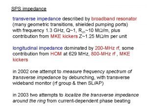
Introduction • L. Vos used this approach for resistive wall impedance calculations (CERN-AB-2003 -093) • Elias Metral, LCE meeting, 20/02/2004 (General formula for the resistive wall impedance derived from L. Vos formalism) • Models based on field matching technique [Zotter/Metral/Salvant/Mounet(Re. Wall), Mounet(IW 2 D), Burov/Lebedev]. • A code based on the transmission line theory has been developed (TLwall).

Overview • Introduction • TLwall – Theory – Benchmarks with Re. Wall/IW 2 D – When could be convenient • Summary

TLwall • TL based theory to calculate the resistive wall impedance of a multilayer round chamber • TL equation can be applied recursively to take into account whatever number of layers. • The code has been implemented in Matlab. A python version has been written by T. Rijoff. The code calculates the wall impedance of a round chamber loaded by a multilayer structure allowing for PEC, Vacuum or Material boundary conditions. • The code was benchmarked with Re. Wall/IW 2 D.

Overview • Introduction • TLwall – Theory – Benchmarks with Re. Wall/IW 2 D – When could be convenient • Summary

TLwall: code for wall impedance calculations Advantage Flexibility, stability, Speed Disadvantage TLwall is in excellent agreement with calculations based on the field matching technique C. Zannini, Electromagnetic simulations of CERN accelerators components, Ph. D thesis

Model description Leontovic Condition

Model description: Impedance calculations Leontovic Condition Ampere Law Longitudinal Impedance Transverse Impedance L. Vos: CERN-AB-2003 -005 ABP The transverse impedance is given by the following formula

Overview • Introduction • TLwall – Theory – Benchmarks with Re. Wall/IW 2 D – When could be convenient • Summary

Benchmark with Re. Wall/IW 2 D: metal with Vacuum boudary Longitudinal impedance g=10000 Pipe radius=18. 4 mm SPS beam pipe TL equation applies to planar geometry Model First layer metal with σ=1. 67 MS/m, thickness=1 mm Boundary condition: Vacuum TLwall overcomes this limitation accounting for the attenuation of cylindrical waves

Benchmark with Re. Wall/IW 2 D: metal with Vacuum boudary Longitudinal impedance g=10000 Pipe radius=18. 4 mm SPS beam pipe TL equation applies to planar geometry Model First layer metal with σ=1. 67 MS/m, thickness=1 mm Boundary condition: Vacuum TLwall overcomes this limitation accounting for the attenuation of cylindrical waves

Benchmark with Re. Wall/IW 2 D: metal with Vacuum boudary Transverse impedance g=10000 Pipe radius=18. 4 mm SPS beam pipe Model First layer metal with σ=1. 67 MS/m, thickness=1 mm Boundary condition: Vacuum

Benchmark with Re. Wall/IW 2 D: metal with magnetic boundary Longitudinal impedance g=10000 Pipe radius=24. 25 mm SPS MBB-MBA chambers Model First layer metal with σ=1. 35 MS/m, thickness=1. 5 mm Boundary condition: Silicon-Steel (material details in Appendix)

Benchmark with Re. Wall/IW 2 D: metal with magnetic boundary Transverse impedance g=10000 Pipe radius=24. 25 mm SPS MBB-MBA chambers Model First layer metal with σ=1. 35 MS/m, thickness=1. 5 mm Boundary condition: Silicon-Steel (material details in Appendix)

Benchmark with Re. Wall/IW 2 D: metal coating and PEC boundary Longitudinal impedance g=10000 Quasi-PEC approximation made in Rewall/IW 2 D Pipe radius=18. 4 mm LHC beamscreen Model First layer metal with σ=1. 82 GS/m, thickness=0. 05 mm Second layer metal with σ=1. 67 MS/m, thickness=1 mm Boundary condition: PEC

Benchmark with Re. Wall/IW 2 D: metal coating and PEC boundary Transverse impedance g=10000 Pipe radius=18. 4 mm LHC beamscreen Model First layer metal with σ=1. 82 GS/m, thickness=0. 05 mm Second layer metal with σ=1. 67 MS/m, thickness=1 mm Boundary condition: PEC

Benchmark with Re. Wall/IW 2 D: ceramic insert (Al 2 O 3) Longitudinal impedance g=10000 Pipe radius=18. 4 mm Model First layer ceramic with σ=1 p. S/m, thickness=1 mm, εr=10 Second layer metal with σ=58 MS/m, thickness=1 mm Boundary condition: PEC

Benchmark with Re. Wall/IW 2 D: ceramic insert (Al 2 O 3) Transverse impedance g=10000 Pipe radius=18. 4 mm Model First layer ceramic with σ=1 p. S/m, thickness=1 mm, εr=10 Second layer metal with σ=58 MS/m, thickness=1 mm Boundary condition: PEC

Benchmark with Re. Wall/IW 2 D: titanium coated ceramic Longitudinal impedance g=10000 Pipe radius=18. 4 mm PSB KSW magnets Model First layer metal with σ=2 MS/m, thickness=1 μm Second layer ceramic with σ=1 p. S/m, thickness=1 mm, εr=10 Third layer metal with σ=58 MS/m, thickness=1 mm Boundary condition: Vacuum

Benchmark with Re. Wall/IW 2 D: titanium coated ceramic Transverse impedance g=10000 Pipe radius=18. 4 mm PSB KSW magnets Model First layer metal with σ=2 MS/m, thickness=1 μm Second layer ceramic with σ=1 p. S/m, thickness=1 mm, εr=10 Third layer metal with σ=58 MS/m, thickness=1 mm Boundary condition: Vacuum

Benchmark with Re. Wall/IW 2 D: nonultrarelativistic case T. Rijoff Circular Vacuum chamber with radius = 31. 5 mm 1 layer = stainless steel (σ = 1. 35 106 S /m ) thickness = 3 mm β = 0. 015

Benchmark with Re. Wall/IW 2 D: dielectric metamaterial insertion and metal boundary A. Danisi, C. Zannini et al. Theoretical analysis of metamaterial insertions for resistive-wall beam-coupling impedance reduction, IPAC 2014

Benchmark with Re. Wall/IW 2 D TLwall benchmarks Metal with Vacuum boundary Metal with material(magnetic) boundary Metal with PEC boundary Ceramic insertion Metal coated ceramics Metamaterials Nonultrarelativistic case TLwall approximations Leontovic condition Usually verified in large ranges of frequencies TL equation applies to planar geometry TLwall overcomes this limitation in the critical case of Vacuum boudaries Beam coupling impedance calculation Approximated radial dependence of the E field Inductive bypass concept of L. Vos The code estimates the maximum frequency the calculation is considered to be accurate

Overview • Introduction • TLwall – Theory – Benchmarks with Re. Wall/IW 2 D – When could be convenient • Summary

TLwall: why in some cases could be convenient? • Calculation is lighter • Building an accelerator wall impedance model based on the machine aperture model (several hundreds of simulations in few seconds) • Using very large number of layers (simulating metamaterial multilayers ) • Model is simpler • Easier to implement modifications for special applications. • Surface impedance obtained with TLwall could be used as input for more complex calculations (e. g. elliptical multilayer chamber Mauro/Nicolo etc. ) • Very difficult to encounter numerical issues • Simulating ideal boundary conditions or very low resistivity • Easy to derive simple expressions in specific cases • Effect of coatings on the imaginary part of the impedance • Getting only the resistive wall impedance (the code gives separately resistive wall and indirect space charge impedance)

TLwall: why in some cases could be convenient? • Calculation is lighter • Building an accelerator wall impedance model based on the machine aperture model (several hundreds of simulations in few seconds) • Using very large number of layers (simulating metamaterial multilayers ) • Model is simpler • Easier to implement modifications for special applications. • Surface impedance obtained with TLwall could be used as input for more complex calculations (e. g. elliptical multilayer chamber Mauro/Nicolo etc. ) • Very difficult to encounter numerical issues • Simulating ideal boundary conditions or very low resistivity • Easy to derive simple expressions in specific cases • Effect of coatings on the imaginary part of the impedance • Getting only the resistive wall impedance (the code gives separately resistive wall and indirect space charge impedance)

Effect of a. C coating on the LHC beamscreen Longitudinal impedance Strong effect of the coating on the imaginary part above a certain frequency

Effect of a. C coating on the LHC beamscreen Transverse impedance Strong effect of the coating on the imaginary part above a certain frequency

Why the imaginary part depends on the a. C coating? • Case without a. C coating • 1 layer structure • 1 st layer (Cu) • Case with a. C coating • 2 layer structure • 1 st layer (a. C) • 2 st layer (Cu) From transmission line theory one can derive the surface impedance seen by the beam Coating thickness The a. C coating introduces an additional contribution to the imaginary impedance Presented at the Impedance meeting on February 16 th 2015

Effect of coatings/insertions on the beam coupling impedance • 1 layer structure • 1 st layer (B) All hypothesis applies to the a. C coating or dielectrics (Al 2 O 3) on metals • 2 layer structure • 1 st layer (F) • 2 st layer (B)

Verification of the formula F layer a. C: σ=400 S/m, εr =5. 4, s=0. 5 μm B layer Cu: σ=1 GS/m

Verification of the formula F layer a. C: σ=400 S/m, εr =5. 4, s=0. 5 μm B layer Cu: σ=1 GS/m

Verification of the formula F layer a. C: σ=400 S/m, εr =5. 4, s=0. 5 μm B layer Cu: σ=1 GS/m

Summary • The python version of TLwall is now available in my afs public directory • The code in several cases of application has been benchmarked with Re. Wall/IW 2 D • Cases where the code could potentially be convenient have been identified • IW 2 D shall always be considered as the reference code since it solves Maxwell equations without approximations.

Thank you very much for your attention

Appendix

Silicon-Steel model for the SPS Silicon-Steel electromagnetic model At low frequency the real part of the longitudinal impedance is much larger with silicon steel boundary
 Electrical length
 Open wire transmission line
 Vector impedance meter determine impedance in
 Structural steel connection calculations calculations
 Designing a zip line math problem
 Mary dahlgren sound walls
 Chris brown wall to wall
 T junction flemish bond
 Members used to carry wall loads over wall openings
 Pod fruit develops from
 Adjustable cross staff in surveying
 Lossless transmission line problems
 Transmission line basics
 Konstanta fasa
 Microstrip transmission line
 Microstrip transmission line
 Mechanical considerations of transmission line
 Two wire communication
 Metallic transmission lines
 L
L Reciprocal network
 Lossless transmission line
 Relational identity
 Horizontal
 Kontinuitetshantering
 List of static series compensators
 Line currents
 Impedence triangle
 Impedance relay
 Earth loop impedance
 The attenuation constant in lossless dielectrics will be
 Equation for gain of op amp
 Op amp gain formula
 Novell typiska drag
 Tack för att ni lyssnade bild
 Ekologiskt fotavtryck
 Series impedance voltmeter
 Shingelfrisyren
 Complex impedence
 Transverse impedance of a string
