Timing How is proper timing achieved Always performed


 250 0")


- Slides: 63
Timing
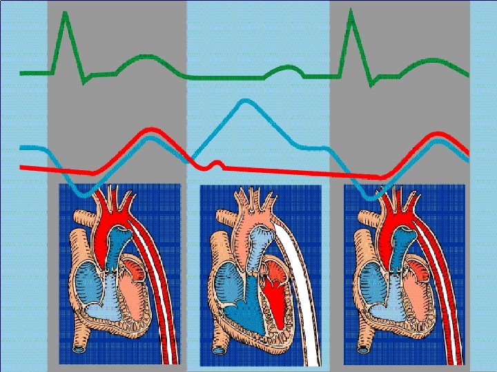
How is proper timing achieved? • Always performed using the arterial pressure waveform as the guide
Arterial Pressure Waveform PSP 75% SV PSP 25% SV DN IVC X AVO AEDP DN X AVO AEDP
Arterial Pressure Waveform Without IABP With IABP Assist 1: 2
Augmentation Peak Systolic Pressure Assisted Peak Systolic Pressure AUG PSP APSP Dicrotic Notch Patient Aortic End Diastolic Pressure DN PAEDP Balloon Aortic End Diastolic Pressure BAEDP
Assist Ratios 1: 1 1: 2 1: 4
Correct Inflation Just prior to DN DN DN
AUG should be higher than PSP Unless: 1. Patient’s SV significantly greater than balloon volume 2. Balloon is positioned too low 3. Hypovolemia 4. Balloon is too small 5. Low SVR 6. Improper timing 7. Partial obstruction of gas flow PSP AUG
Correct Deflation PSP BAEDP < PAEDP APSP < PSP APSP PAEDP BAEDP
Poor afterload reduction PSP May be caused by: 1. Balloon not large enough or not filled to full volume PAEDP 2. Compliant aortic wall 3. Improper placement 4. Partial obstruction of gas flow APSP BAEDP
Timing Errors • • Early Inflation Late Inflation Early Deflation Late Deflation
Early Inflation
Early Inflation AUG DN move inflation Correct Timing
Late Inflation
Late Inflation AUG DN move inflation Correct Timing
Early Deflation
Early Deflation PSP APSP move deflation Correct Timing
Late Deflation
Late Deflation BAEDP PAEDP move deflation Correct Timing
NYHA class III patient, EF 25%, during off-pump CABG. HR varied between 73139 bpm with significant changes in Pulse Pressure on a beat to beat basis.
Auto. Pilot™ Mode • Automatically selects the best available ECG source / lead • Automatically selects the AP source • Automatically selects the appropriate trigger mode • Automatically selects the optimal timing method and settings
Operator Mode Clinician selects: • • ECG source / lead AP source Trigger mode Timing settings
Both Modes • Automatically adjust ECG gain – Unless manual gain function selected • Automatically selects AP scale – Unless manual scale function selected • User can select ECG source / lead and AP source
Triggering
Definition The computer in the IAB console needs a stimulus to cycle the pneumatic system which inflates and deflates the balloon. The trigger signal tells the computer that another cardiac cycle has begun.
Options In most cases it is preferable to use the R wave of the ECG as the trigger signal. However, the operator also has the option of using the arterial pressure waveform or pacing spikes as the trigger event.
Patient Signal Connections Direct connections are always best
Monitor “Slaved” ECG Direct HP Merlon Marquette Tram Space. Labs Use 4 or 5 Lead cable
Monitor “Slaved” AP Direct one of these HP Merlon Marquette Tram Space. Labs Fiber Optic AP connection if Light. WAVE™ catheter is used
FOR GOOD, CONSISTENT TRIGGERING IT IS IMPORTANT TO PROVIDE THE PUMP WITH A GOOD ECG SIGNAL Good Choices – Unidirectional QRS with minimal artifact Poor Choices – Biphasic QRS, tall T or P waves, wandering baseline, artifact present
This lead will give you both triggering and timing problems
ECG Pattern This is the preset trigger mode. The computer analyzes the height, width (25135 msec), and slope of a positively or negatively deflected QRS complex. Rejection of pacer spikes is automatic. Auto. Pilot™’s choice when the QRS complex is normal and the HR < 130
ECG Peak The computer analyzes the height and slope of a positively or negatively deflected QRS complex. This may be the trigger mode of choice for wide complex or rapid rhythms. Rejection of pacer spikes is automatic. Auto. Pilot™’s choice when the QRS complex is wide, the HR > 130, or during arrhythmia when Arrhythmia Timing is OFF.
AFIB The computer analyzes the QRS complex in the same manner as Peak mode an initiates “Real-Time” timing. Deflation is automatic when the next trigger event is identified, allowing for more consistent deflation timing when R to R intervals are irregular. Rejection of pacer spikes is automatic. Auto. Pilot™’s choice the rhythm is irregular and Arrhythmia Timing is ON.
Timing with Irregular Rhythms “Real-Time” Timing Conventional Timing
Arterial Pressure HR The computer uses the systolic upstroke of the arterial pressure waveform as the trigger signal. This mode is an option when an ECG is unavailable or distorted. Auto. Pilot™’s choice when there are no R-waves available.
V Pace The computer uses the ventricular spike as the trigger signal. This mode can be used with ventricular or AV paced rhythms. Must be 100% paced. Auto. Pilot™’s uses this mode when there are no Rwaves or AP waveforms present, however, there are V or AV pacer spikes.
A Pace The computer uses the atrial pacing spike as the trigger signal. This mode can be used with atrially paced rhythms only. Must be 100% paced. Auto. Pilot™’s choice when the ECG is intermittent and pacer spike to R wave is > 100 ms.
Internal The balloon inflates and deflates at a preset rate regardless of the patient’s cardiac activity. This mode is only to be used when there is no cardiac output and no ECG. Preset rate is 80 bpm; can be varied between 40 to 120.
Cardiac Arrest What do you do with the IABP?
Helium Delivery
Pneumatic Systems 2 types of gas delivery systems: Vacuum / compressor system Bellows / stepper motor system
Balloon Pressure Waveform 4 1. Zero Baseline 2. Balloon Pressure Baseline 3. Rapid Inflation 5 3 9 4. Peak Inflation Artifact 5. Plateau Pressure 6 6. Rapid Deflation 8 2 1 7. Deflation Artifact 8. Return to Baseline 7 9. Duration of Balloon Cycle
Helium Fill Pressure BPW Stepper motor / bellows system 0 transducer pump helium
Balloon Inflation BPW Stepper motor / bellows system 0 transducer pump helium
Balloon Deflation BPW Stepper motor / bellows system 0 transducer pump helium
Heart Rate Variations 250 0 0 Tachycardia Bradycardia
BPW in Irregular Diastole (Afib) 250 0
Pressure Variations 250 0 0 Hypertension Hypotension
Comparison of Augmented AP waveform and Plateau of Balloon Pressure waveform
Intra-aortic Relationship of Inflated Balloon Catheter and Vascular Pressure transmembrane pressure 250 50 aorta IAB fully inflated aorta 150 0 Note that the endpoint of the BPW plateau should be equal or up to 20 mm. Hg higher than the Augmented Pressure.
Troubleshooting Gas Surveillance Alarms
Purge Failure Pump did not fill adequately with helium to establish the balloon pressure waveform baseline 250 0 Verify: Helium tank not empty Catheter connections intact Trigger present
High Baseline 250 0 Check for: 1. Partially wrapped balloon 2. Kinked catheter
Helium Loss 250 0 Check for: 1. Leak in tubing and connections 2. Blood in catheter tubing 3. Kinked catheter 4. Ectopic beats
Classic BPW appearance of a Kinked Catheter
Internal Leak Test pass fail Observe BPW baseline for 1 - 2 minutes BALLOON • Turn alarms OFF • Select INTERNAL trigger
IAB too Large for Aortic Environment BPW 0 transducer pump helium
Hands on review of the Auto. CAT® 2 WAVETM