Timers Lecture L 4 4 Reference TIM16 B

Timers Lecture L 4. 4

Reference TIM_16 B 8 C Block User Guide S 12 TIM 16 B 8 CV 1. pdf

Timers • • • The 9 S 12 C 32 Programmable Timer Output Compares Pulse Train Using Interrupts Input Capture Measuring the Period of a Pulse Train Using Interrupts

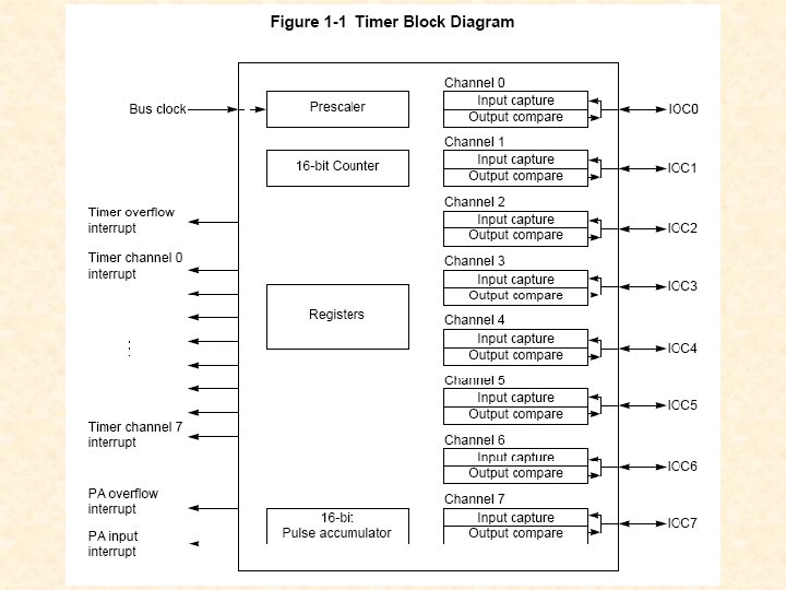
PIM_9 DP 256 Block Diagram Timer module

")
Timer Counter Timer Count Register (TCNT)

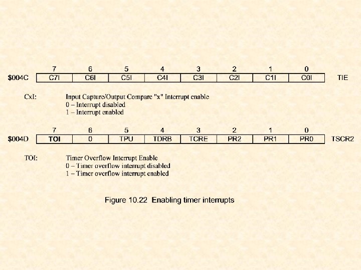
Timer System Control Register 1
")
Setting the timer count time Timer System Control Register 2 (TSCR 2)
")
Main Timer Interrupt Flag 2 (TFLG 2)
")
Timer Input Capture/Output Compare Select (TIOS)

Timers • • • The 9 S 12 DP 256 Programmable Timer Output Compares Pulse Train Using Interrupts Input Capture Measuring the Period of a Pulse Train Using Interrupts
")
Timer Input Capture/Output Compare Registers 0 -7 Main Timer Interrupt Flag 1 (TFLG 1)

; TIOS TCNT TSCR 1 TSCR 2 TFLG 1 TC 6 OUTA Delay using Output Compares EQU $0040 ; Timer Inp Cap. Out Comp. Sel EQU $0044 ; Timer Counter Register EQU $0046 ; Timer System Control Reg 1 EQU $004 D ; Timer System Control Reg 2 EQU $004 E ; Timer Interrupt Flag Reg 1 EQU $005 C ; Timer Output Compare Reg 6 EQU $FF 4 F ORG $4000 jsr ldb tba jsr bsr decb bne swi timer_init #10 main mn 1 hexasc outa second_delay mn 1

timer_init ldaa staa ldd std rts #$40 tios #$02 tscr 2 #$80 tscr 1 tcnt tc 6 ; select output compare 6 ; div by 4: 2 MHz timer clock ; enable timer ; tc 6 = current count

ms 25_delay msd 1 pshd ldd addd std ldaa staa ldaa anda beq puld rts ; 25 msec delay ; save D tc 6 #50000 tc 6 #$40 tflg 1 #$40 msd 1 ; clear outpt comp 6 flag ; wait for timeout ; restore D second_delay pshb ldab bsr decb bne pulb rts ; add 50000 to prev count #40 ms 25_delay sd 1 ; delay 1 second ; save B ; 40 x 25 ms = 1000 ms ; delay 25 ms ; 40 times

Pulse Train Example


; Pulse train using output compares 7 and 6 TIOS OC 7 M OC 7 D TCNT TSCR 1 TCTL 1 TSCR 2 TFLG 1 TC 6 TC 7 equ $0040 ; Timer Input Cap. ; Output Comp. Select equ $0042 ; Output Compare 7 Mask Register equ $0043 ; Output Compare 7 Data Register equ $0044 ; Timer Counter Register equ $0046 ; Timer System Control Register 1 equ $0048 ; Timer Control Register 1 equ $004 D ; Timer System Control Register 2 equ $004 E ; Timer Interrupt Flag Register 1 equ $005 C ; Timer Output Compare Register 6 equ $005 E ; Timer Output Compare Register 7 ORG p_width period $800 dw dw 6625 17500

tinit ldaa staa ldaa staa clr ldaa staa rts #$c 0 TIOS #$02 TSCR 2 #$80 TSCR 1 TCNT TC 6 TC 7 #$40 OC 7 M OC 7 D #$30 TCTL 1 ; select output compares 6 & 7 ; div by 4: 2 MHz timer clock ; enable timer ; init cnt in TC 6 & TC 7 ; pulse train out PT 6 ; PT 6 goes low on TC 7 match ; set PT 6 high on TC 6 match

ORG $4000 bsr ldaa staa ldd addd std ldaa anda beq bra tinit #$c 0 tflg 1 tc 7 period tc 7 p_width tc 6 tflg 1 #$40 pl 2 pl 1 pulse pl 1 pl 2 ; initialize timer ; clear output flags 6 and 7 ; TC 7 new = TC 7 old + PERIOD ; TC 6 = TC 7 new + P_WIDTH ; wait for PT 6 to go low on ; TC 7 match and then high on ; TC 6 match

Timers • • • The 9 S 12 DP 256 Programmable Timer Output Compares Pulse Train Using Interrupts Input Capture Measuring the Period of a Pulse Train Using Interrupts

Pulse Train

; Pulse train using output compares 7 and 6 TIOS equ $0040 ; Timer Input Cap. ; Output Comp. Select OC 7 M equ $0042 ; Output Compare 7 Mask Register OC 7 D equ $0043 ; Output Compare 7 Data Register TCNT equ $0044 ; Timer Counter Register TSCR 1 equ $0046 ; Timer System Control Register 1 TCTL 1 equ $0048 ; Timer Control Register 1 TIE equ $004 C ; Timer Interrupt Enable Register 1 TSCR 2 equ $004 D ; Timer System Control Register 2 TFLG 1 equ $004 E ; Timer Interrupt Flag Register 1 TC 6 equ $005 C ; Timer Output Compare Register 6 TC 7 equ $005 E ; Timer Output Compare Register 7 TC 6_IVEC equ $0 FE 4 ; Timer Channel 6 interrupt vector ORG p_width period $800 dw dw ORG 6625 17500 $4000 pulsei pl 1 bsr bra tinit pl 1 ; initialize timer

tinit sei ldaa staa ldaa staa clr ldaa staa ldd std ldaa staa cli rts ; disable interrupts #$c 0 TIOS #$02 TSCR 2 #$80 TSCR 1 TCNT TC 6 TC 7 #$40 OC 7 M OC 7 D #$30 TCTL 1 #tc 6_intser TC 6_IVEC #$40 TIE ; select output compares 6 & 7 ; div by 4: 2 MHz timer clock ; enable timer ; init cnt in TC 6 & TC 7 ; pulse train out PT 6 ; PT 6 goes low on TC 7 match ; set PT 6 high on TC 6 match ; save int vector ; enable TC 6 interrupts ; enable interrupts

tc 6_intser ldd addd std ldaa staa rti tc 7 period tc 7 p_width tc 6 #$c 0 tflg 1 ; TC 7 new = TC 7 old + PERIOD ; TC 6 = TC 7 new + P_WIDTH ; clear output flags 6 and 7

Timers • • • The 9 S 12 DP 256 Programmable Timer Output Compares Pulse Train Using Interrupts Input Capture Measuring the Period of a Pulse Train Using Interrupts

Input Capture

pwidth. asm ; Use input capture to measure width of single pulse. ; Polling mode -- no interrupts ; Use TC 2 -- signal on PT 2 TIOS TCNT TSCR 1 TCTL 4 TIE TSCR 2 TFLG 1 TC 2 pwidth equ $0040 ; Timer Input Cap. ; Output Comp. Select equ $0044 ; Timer Counter Register equ $0046 ; Timer System Control Register 1 equ $004 B ; Timer Control Register 4 equ $004 C ; Timer Interrupt Enable Register 1 equ $004 D ; Timer System Control Register 2 equ $004 E ; Timer Interrupt Flag Register 1 equ $0054 ; Timer Input Capture Register 6 org dw $800 0
 org $4000 main bsr swi tic_init clr ldaa staa rts")
pwidth. asm (cont. ) org $4000 main bsr swi tic_init clr ldaa staa rts tic_init pulse_width ; initialize timer ; measure single pulse width tios tscr 2 #$80 tscr 1 ; select all input captures ; div by 1: 8 MHz timer clock ; enable timer
 pulse_width pw 1 pw 2 ldaa staa ldaa anda beq")
pwidth. asm (cont. ) pulse_width pw 1 pw 2 ldaa staa ldaa anda beq ldd std ldaa staa ldaa anda beq ldd ldaa staa subd std rts #$10 tctl 4 #$04 tflg 1 #$40 pw 1 tc 2 2, -sp #$04 tflg 1 #$20 tctl 4 tflg 1 #$40 pw 2 tc 2 #$04 tflg 1 2, sp+ pwidth ; capture on rising edge ; clear C 2 F flag ; wait for rising edge ; read t 1 ; save t 1 ; clear C 2 F flag ; capture on falling edge ; wait for falling edge ; read t 2 ; clear C 2 F flag ; d = t 2 - t 1 ; save pwidth

Timers • • • The 9 S 12 DP 256 Programmable Timer Output Compares Pulse Train Using Interrupts Input Capture Measuring the Period of a Pulse Train Using Interrupts

; Measuring the period of a pulse train. ; Use interrupts ; Use TC 1 -- signal on PT 1 TIOS equ $0040 ; Timer Input Cap. ; Output Comp. Select TCNT equ $0044 ; Timer Counter Register TSCR 1 equ $0046 ; Timer System Control Register 1 TCTL 4 equ $004 B ; Timer Control Register 4 TIE equ $004 C ; Timer Interrupt Enable Register 1 TSCR 2 equ $004 D ; Timer System Control Register 2 TFLG 1 equ $004 E ; Timer Interrupt Flag Register 1 TFLG 2 equ $004 F ; Timer Interrupt Flag Register 2 TC 1 equ $0054 ; Timer Input Capture Register 1 TC 1_IVEC equ $0 FEE ; Timer Channel 1 interrupt vector TOF_IVEC equ $0 FE 0 ; Timer overflow flag interrupt vector Out 1 byt equ $FF 52 ; display hex value of byte at X ovcnt_old tic 1_old dperiod org dw dw dw rmb $800 0 4

init_ic sei clr ldaa staa staa ldaa staa ldd std cli rts tios tscr 2 #$80 tscr 1 #$40 tctl 4 #$02 tflg 1 #$80 tflg 2 tscr 2 #$20 tie #tc 1_intser TC 1_IVEC #tof_intser TOF_IVEC ; select input capture 1 ; div by 1: 8 MHz timer clock ; enable timer ; rising edge of TC 1 ; clear any old flags ; enable TOI interrupt ; enable TC 1 interrupt ; save int vector

tof_intser ldd addd std ldaa staa rti ovcnt #1 ovcnt #$80 tflg 2 ; inc ovcnt ; clear TOF ovcnt TC 1 ovcnt_old tic 1_old

tc 1_intser ldd std ldd std tsx bsr ldd std ldaa staa rti tc 1 2, -sp ovcnt 2, -sp tic 1_old 2, -sp ovcnt_old 2, -sp 6, sp tic 1_old 4, sp ovcnt_old dminus 0, x dperiod 2, x dperiod+2 #$02 tflg 1 ; get new inp capture ; push it ; get new ovcnt ; push it ; get old inp capture ; push it ; get old ovcnt ; push it ; get new inp capture ; store it in tic 1_old ; get new ovcnt ; store it in ovcnt_old ; x = sp ; x -> ddiff ; store dperiod ; clear C 1 F flag

Subtracting Double Numbers ovcnt_old tc 1 tic 1_old

org $4000 bsr ldx ldab jsr decb bne ldy jsr bra init_ic #dperiod #4 out 1 byt main mn 0 mn 1 #30 ms_delay mn 0 ; initialize timer ; output dperiod ; to screen ; continuously
- Slides: 39