
Time Calibration Transition from ARCA Phase 1 to

Time Calibration • Transition from ARCA Phase 1 to ARCA Phase 2 ARCA Phase 1: Hybrid WR implementation (see Time Calibration TDR) DOM “hybrid” WR -> GPS time broadcasted from shore DU Base CLB “full” WR -> RTT Measurement 06/04/2017 Time Cal meeting G. Riccobene INFN - LNS 1
Time Calibration 06/04/2017 Time Cal meeting G. Riccobene INFN - LNS 2
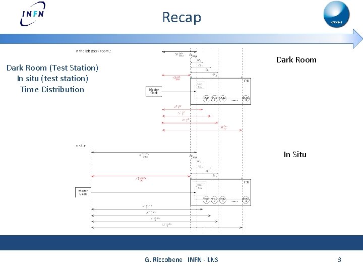
Recap Dark Room (Test Station) In situ (test station) Time Distribution In Situ G. Riccobene INFN - LNS 3
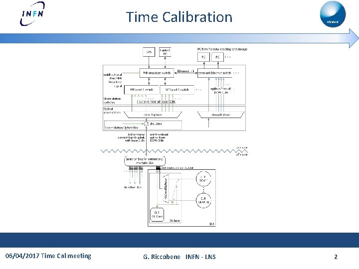
Time Calibration The WR gear of the CLB in the base is used for measuring the WR RTT_Cable DOM Time Calibration (inter-DU): All asymmetries due to fiber lenghts or chromatic dispersion in the MEOC are cancelled or measured on-shore and properly taken into-account off-line. • Cancelled: o measurement of RTT_Cable in situ and RTT_Cable in the dark room o SC/DC fiber length asymmetry in the base o SC/DC fiber lenght asymmetries in Dark Room (Test Station) / in Situ (Shore Station) • Offline calculation: o c(λ) in MEOC fibres: measured before deployment o SC/DC node (JB) asymmetry: measured before deployment Time Calibration of Bases: The base is synthonised (fixed frequency) and “synchronised” (fixed time delay) but the absolute time of the base remains unknown (due to the base SC/DC asymmetry, not measured) 06/04/2017 Time Cal meeting G. Riccobene INFN - LNS 4

Recap Take into account different asymmetries of components used in the shore station and in the test station: use WR RTT_Cable Dark Room G. Riccobene INFN - LNS In Situ 5
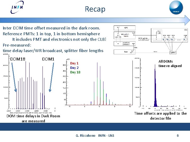
Recap Inter DOM time offset measured in the dark room. Reference PMTs: 1 in top, 1 in bottom hemisphere It includes PMT and electronics not only the CLB! Pre-measured: time delay laser/WR broadcast, splitter fiber lengths DOM 18 DOM 1 Day 2 Day 18 All DOMs time re-aligned Time offsets are applied to the detector file DOM time delays in Dark Room are measured G. Riccobene INFN - LNS 6
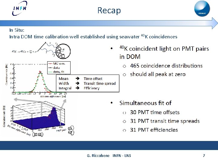
Recap In Situ: Intra DOM time calibration well established using seawater 40 K coincidences G. Riccobene INFN - LNS 7
Open issues for Phase 1 (and beyond) How to treat the case of multiple broadcast switches/lines ? In the present optical system implementation 1 optical line per each JB is foreseen to distribute the broadcast signal. The actual WR fw implies use of N broadcast switches for N JBs (only port 18 sends the broadcast signal now) T. Chiarusi: ask 7 sol to mirror the WR Broadcast output in other ports Need to: Syncronise the N WR Broadcast switches Measure the SS RTT for each broadcast line Is this extendable to approx 30 JBs ? G. Riccobene INFN - LNS 8
Open issues for Phase 1 (and beyond) 1 broadcast fiber per JB 2 x G. Riccobene INFN - LNS 9
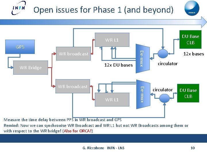
Open issues for Phase 1 (and beyond) DU Base CLB WR L 1 GPS 12 x DU bases De-mux WR L 1 De-mux WR broadcast WR Bridge WR broadcast 12 x bases circulator DU Base CLB Measure the time delay between PPS in WR broadcast and GPS Remind: Now we can synchronise WR Broadcast and WR L 1 but not WR Broadcasts among them or with respect to the WR bridge! (Also for ORCA!) G. Riccobene INFN - LNS 10
Open issues for Phase 1 (and beyond) DOMs keeps operating in “hybrid mode” both in actual solution (no ethernet switch in the base) or with aggregation ethernet switch in the base for DOM data All the rest of the calibration procedure (Dark Room inter-DOM, in Situ 40 K) holds as per the TDR G. Riccobene INFN - LNS 11
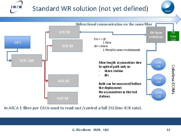
Standard WR solution (not yet defined) Bidirectional communication on the same fiber WR M GPS WR M WR GM DU <-> JB 1 fibre JB<->shore 1 fibre(DU colors multiplexed) WR M Both can be measured before the deployment. No asymmetries in the test stations. DU Base CLB DOM CLB Colorless DOMs Fiber length asymmetries due to optical path only in: - shore station - JBs DU Base switch(es) DOM CLB In ARCA 1 fibre per DU is used to read-out /control a full DU (low 40 K rate). G. Riccobene INFN - LNS 12
Standard WR solution RTT measurements (Cable RTT, α, hardware delays [TXM, TXS, RXM, RXS]): Shore <-> DU base switch(es) DOMs <-> DU base switch(es) Can we synchronise each slave (CLB) to the master clock only by “WR electronics” data? Standard WR method: align PPS of master and slaves (before integrating DOMs) All CLBs have the same hardware delay? So, one CLB can represent all? (in theory) If so: hw delays parameters (master/slave) can be easily determined for all CLBs If not: synchronise each CLB (too costly/time effective) Dark Room calibration Also: each WR switch port has its own Hw delays parameters set. To our experience, these are not perfectly corrected through tables in fw 3. 1 (± 500 ps among ports). Need to understand how this is treated in newer WR fw versions. In case this is not solved: need to calibrate all WR switch ports (230 x 2 DUs) before installation. This also applies to the switch in the base (DOM<->DU base switch) we can always rely on Dark Room calibration G. Riccobene INFN - LNS 13
Standard WR solution “Phase 1 -like approach” for time calibration: Intra-DOM: 40 K calibration in situ Inter-DOM, Inter-DU Do not set CLB hw delays parameters to synchronise CLBs to the Master into the wrs_hal. conf file, only add them in the detector file Dark Room laser calibration : DOM (reference PMT)<-> DU base switch time delays check time synchronisation between 2 DU base switches (the second switch on the DU is synchonised as “slave”) DU base switches <-> shore station: bidirectional link on 1 fibre hw delays of each device are measured with respect to a “KM 3 Ne. T WR calibrator” e. g. a reference CLB. G. Riccobene INFN - LNS 14
Standard WR solution “Standard WR approach” for time calibration (needs more investigation): Intra-DOM: 40 K calibration in situ Inter-DOM, Inter-DU: Set hw delays parameters of all WR elements (including CLB) to synchronise Master and Slaves into the wrs_hal. conf file (including node and SS time asymmetries) -> Doable only if all CLBs and switches have the same time latencies Dark Room laser calibration: verification of RTT + PMT/CLB delay DOM (reference PMT)<-> DU base switch time delays DU base switches <-> shore station: bidirectional link on 1 fiber G. Riccobene INFN - LNS 15
What can we gain? Almost all the developed procedures for time calibration apply in the case of full WR solution Ease of calibration procedures: simpler pre-calibration measurement of the test station (slide 5) simpler detector file arrangement (node asymmetries, SS asymmetries, Dark room delays, intra dom delays) ease of synchronisation to the MC. Maintainability: Simplified test/shore station (ease of component replacement in case of failure) Scalability: add one layer between GM and WR fabric element communicating with Dus (requires only PPS synchronisation of the new layer elements) G. Riccobene INFN - LNS 16
What can we gain? Additional handles: RTT DOM<-> DU Base switch: monitor time delay stabilty vs time (pressure/temperature/…) Additional CLB on the JB (CLB is needed for EDFA control) accurate measurement of α along the MEOC Bases synchronised wrt master clock (recover detector absolute time in laser beacon runs) G. Riccobene INFN - LNS 17
Comparison Matrix G. Riccobene INFN - LNS 18
- Slides: 18