
Timber Tectonics in the Digital Age Cody Knights

Timber Tectonics in the Digital Age Cody Knight’s PORTFOLIO PROFESSORS MARIAPAOLA RIGGIO AND NANCY YEN-WEN CHENG SPRING 2018
Learning Goals My personal goals for this course: 1) Gain a deeper understanding on design and structural systems with engineered wood products 2) Gain experience in parametric design (3 D modeling) 3) Gain experience working and communicating with people of different disciplines AUTHOR’S NAME TIMBER TECTONICS IN THE DIGITAL AGE – SPRING 2018 WEEK # 2
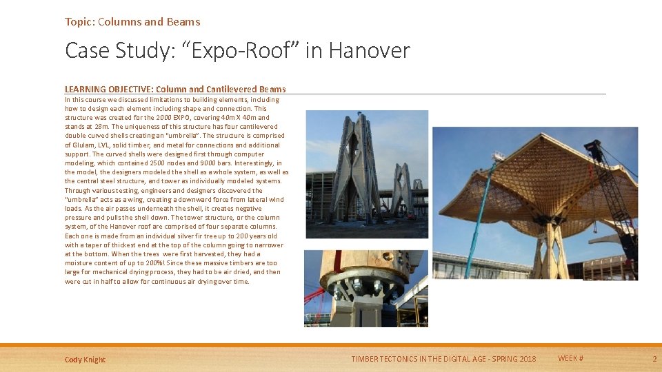
Topic: Columns and Beams Case Study: “Expo-Roof” in Hanover LEARNING OBJECTIVE: Column and Cantilevered Beams In this course we discussed limitations to building elements, including how to design each element including shape and connection. This structure was created for the 2000 EXPO, covering 40 m X 40 m and stands at 28 m. The uniqueness of this structure has four cantilevered double curved shells creating an “umbrella”. The structure is comprised of Glulam, LVL, solid timber, and metal for connections and additional support. The curved shells were designed first through computer modeling, which contained 2500 nodes and 9000 bars. Interestingly, in the model, the designers modeled the shell as a whole system, as well as the central steel structure, and tower as individually modeled systems. Through various testing, engineers and designers discovered the “umbrella” acts as a wing, creating a downward force from lateral wind loads. As the air passes underneath the shell, it creates negative pressure and pulls the shell down. The tower structure, or the column system, of the Hanover roof are comprised of four separate columns. Each one is made from an individual silver fir tree up to 200 years old with a taper of thickest end at the top of the column going to narrower at the bottom. When the trees were first harvested, they had a moisture content of up to 200%! Since these massive timbers are too large for mechanical drying process, they had to be air dried, and then were cut in half to allow for continuous air drying over time. Cody Knight TIMBER TECTONICS IN THE DIGITAL AGE - SPRING 2018 WEEK # 2
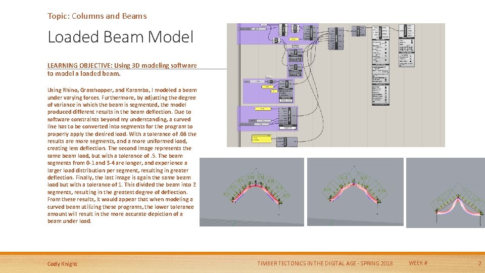
Topic: Columns and Beams Loaded Beam Model LEARNING OBJECTIVE: Using 3 D modeling software to model a loaded beam. Using Rhino, Grasshopper, and Karamba, I modeled a beam under varying forces. Furthermore, by adjusting the degree of variance in which the beam is segmented, the model produced different results in the beam deflection. Due to software constraints beyond my understanding, a curved line has to be converted into segments for the program to properly apply the desired load. With a tolerance of. 08 the results are more segments, and a more uniformed load, creating less deflection. The second image represents the same beam load, but with a tolerance of. 5. The beam segments from 0 -1 and 3 -4 are longer, and experience a larger load distribution per segment, resulting in greater deflection. Finally, the last image is again the same beam load but with a tolerance of 1. This divided the beam into 2 segments, resulting in the greatest degree of deflection. From these results, it would appear that when modeling a curved beam utilizing these programs, the lower tolerance amount will result in the more accurate depiction of a beam under load. Cody Knight TIMBER TECTONICS IN THE DIGITAL AGE - SPRING 2018 WEEK # 2
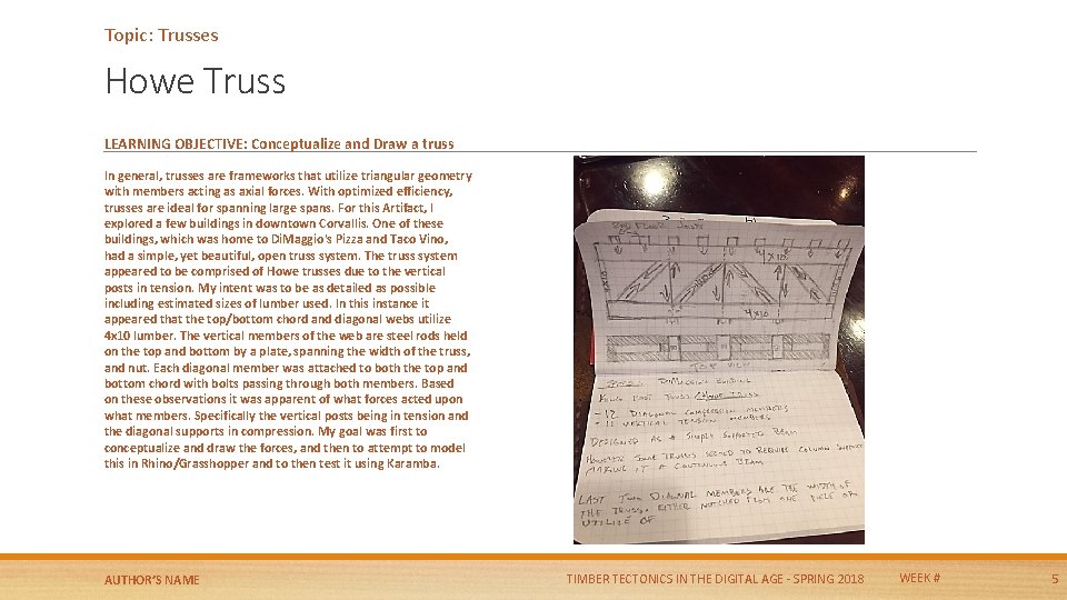
Topic: Trusses Howe Truss LEARNING OBJECTIVE: Conceptualize and Draw a truss In general, trusses are frameworks that utilize triangular geometry with members acting as axial forces. With optimized efficiency, trusses are ideal for spanning large spans. For this Artifact, I explored a few buildings in downtown Corvallis. One of these buildings, which was home to Di. Maggio's Pizza and Taco Vino, had a simple, yet beautiful, open truss system. The truss system appeared to be comprised of Howe trusses due to the vertical posts in tension. My intent was to be as detailed as possible including estimated sizes of lumber used. In this instance it appeared that the top/bottom chord and diagonal webs utilize 4 x 10 lumber. The vertical members of the web are steel rods held on the top and bottom by a plate, spanning the width of the truss, and nut. Each diagonal member was attached to both the top and bottom chord with bolts passing through both members. Based on these observations it was apparent of what forces acted upon what members. Specifically the vertical posts being in tension and the diagonal supports in compression. My goal was first to conceptualize and draw the forces, and then to attempt to model this in Rhino/Grasshopper and to then test it using Karamba. AUTHOR’S NAME TIMBER TECTONICS IN THE DIGITAL AGE - SPRING 2018 WEEK # 5
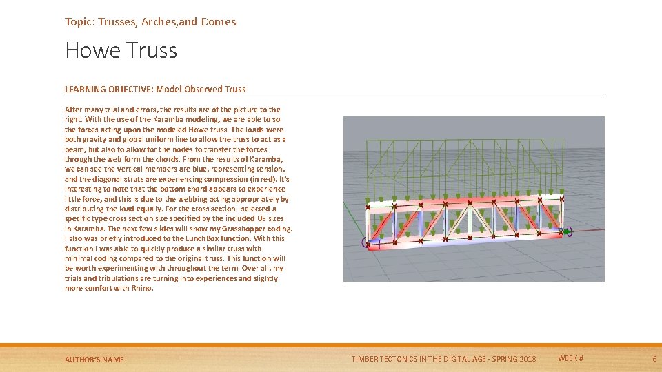
Topic: Trusses, Arches, and Domes Howe Truss LEARNING OBJECTIVE: Model Observed Truss After many trial and errors, the results are of the picture to the right. With the use of the Karamba modeling, we are able to so the forces acting upon the modeled Howe truss. The loads were both gravity and global uniform line to allow the truss to act as a beam, but also to allow for the nodes to transfer the forces through the web form the chords. From the results of Karamba, we can see the vertical members are blue, representing tension, and the diagonal struts are experiencing compression (in red). It’s interesting to note that the bottom chord appears to experience little force, and this is due to the webbing acting appropriately by distributing the load equally. For the cross section I selected a specific type cross section size specified by the included US sizes in Karamba. The next few slides will show my Grasshopper coding. I also was briefly introduced to the Lunch. Box function. With this function I was able to quickly produce a similar truss with minimal coding compared to the original truss. This function will be worth experimenting with throughout the term. Over all, my trials and tribulations are turning into experiences and slightly more comfort with Rhino. AUTHOR’S NAME TIMBER TECTONICS IN THE DIGITAL AGE - SPRING 2018 WEEK # 6
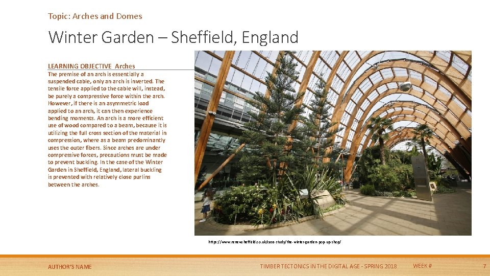
Topic: Arches and Domes Winter Garden – Sheffield, England LEARNING OBJECTIVE Arches The premise of an arch is essentially a suspended cable, only an arch is inverted. The tensile force applied to the cable will, instead, be purely a compressive force within the arch. However, if there is an asymmetric load applied to an arch, it can then experience bending moments. An arch is a more efficient use of wood compared to a beam, because it is utilizing the full cross section of the material in compression, where as a beam predominantly uses the outer fibers. Since arches are under compressive forces, precautions must be made to prevent buckling. In the case of the Winter Garden in Sheffield, England, lateral buckling is prevented with relatively close purlins between the arches. https: //www. renewsheffield. co. uk/case-study/the-winter-garden-pop-up-shop/ AUTHOR’S NAME TIMBER TECTONICS IN THE DIGITAL AGE - SPRING 2018 WEEK # 7
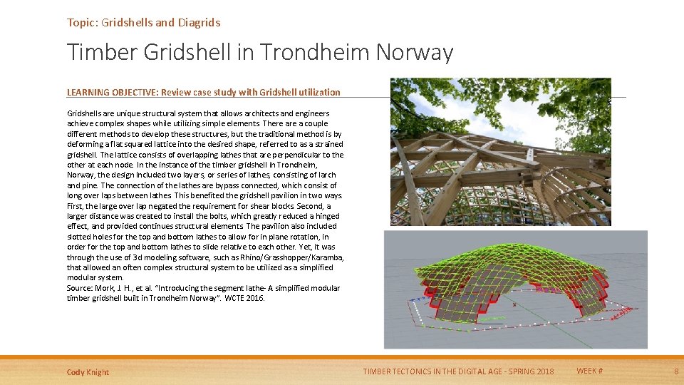
Topic: Gridshells and Diagrids Timber Gridshell in Trondheim Norway LEARNING OBJECTIVE: Review case study with Gridshell utilization Gridshells are unique structural system that allows architects and engineers achieve complex shapes while utilizing simple elements. There a couple different methods to develop these structures, but the traditional method is by deforming a flat squared lattice into the desired shape, referred to as a strained gridshell. The lattice consists of overlapping lathes that are perpendicular to the other at each node. In the instance of the timber gridshell in Trondheim, Norway, the design included two layers, or series of lathes, consisting of larch and pine. The connection of the lathes are bypass connected, which consist of long over laps between lathes. This benefited the gridshell pavilion in two ways. First, the large over lap negated the requirement for shear blocks. Second, a larger distance was created to install the bolts, which greatly reduced a hinged effect, and provided continues structural elements. The pavilion also included slotted holes for the top and bottom lathes to allow for in plane rotation, in order for the top and bottom lathes to slide relative to each other. Yet, it was through the use of 3 d modeling software, such as Rhino/Grasshopper/Karamba, that allowed an often complex structural system to be utilized as a simplified modular system. Source: Mork, J. H. , et al. “Introducing the segment lathe- A simplified modular timber gridshell built in Trondheim Norway”. WCTE 2016. Cody Knight TIMBER TECTONICS IN THE DIGITAL AGE - SPRING 2018 WEEK # 8
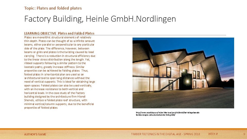
Topic: Plates and folded plates Factory Building, Heinle Gmb. H. Nordlingen LEARNING OBJECTIVE Plates and Folded Plates are monolithic structural elements of relatively thin depth. Plates can be thought of as a infinite amount beams, either parallel or perpendicular to any particular side of the plate. The difference, however, between beams or grids and plates is the twisting caused by load carrying. There is a reduction in structural efficiency due to the linear stress distribution along the length. Yet, ribbed supports following a similar pattern to the isostatic paths, greatly increase stiffness. Similar properties can be achieved by folding plates. Thus, folded plates in a horizontal plan are used as an architectural tool to span long distances without the need of vertical supports. This is ideal for obtaining large open spaces. Folded plates can also be used vertically, with an increase resistance to both vertical and horizontal loads. In the case study of the Factory building designed by the architecture firm Hiendl Sheneis, utilizes a folded plate roof structure, with minimal vertical/column supports, due to the beneficial properties of folded plates. http: //www. wooddays. eu/hr/architecture/projekt/detail/betriebsgebaeudeheinle-energie-und-automationstechnik-gmbh/ AUTHOR’S NAME TIMBER TECTONICS IN THE DIGITAL AGE - SPRING 2018 WEEK # 9
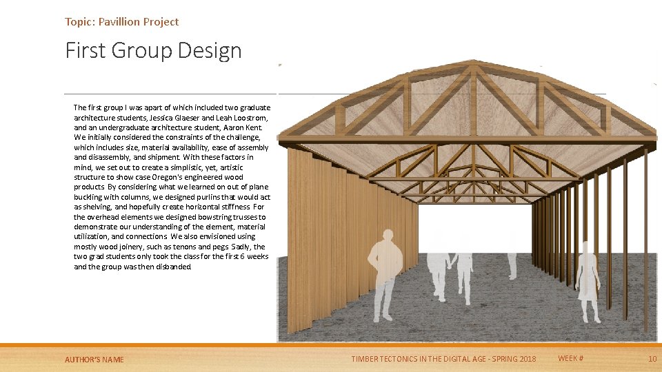
Topic: Pavillion Project First Group Design The first group I was apart of which included two graduate architecture students, Jessica Glaeser and Leah Loostrom, and an undergraduate architecture student, Aaron Kent. We initially considered the constraints of the challenge, which includes size, material availability, ease of assembly and disassembly, and shipment. With these factors in mind, we set out to create a simplistic, yet, artistic structure to show case Oregon's engineered wood products. By considering what we learned on out of plane buckling with columns, we designed purlins that would act as shelving, and hopefully create horizontal stiffness. For the overhead elements we designed bowstring trusses to demonstrate our understanding of the element, material utilization, and connections. We also envisioned using mostly wood joinery, such as tenons and pegs. Sadly, the two grad students only took the class for the first 6 weeks and the group was then disbanded. AUTHOR’S NAME TIMBER TECTONICS IN THE DIGITAL AGE - SPRING 2018 WEEK # 10
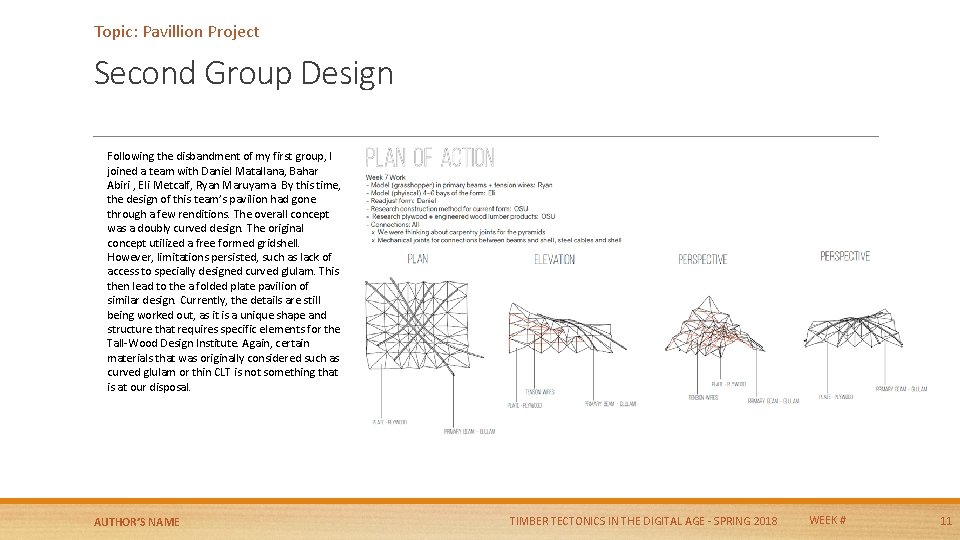
Topic: Pavillion Project Second Group Design Following the disbandment of my first group, I joined a team with Daniel Matallana, Bahar Abiri , Eli Metcalf, Ryan Maruyama. By this time, the design of this team’s pavilion had gone through a few renditions. The overall concept was a doubly curved design. The original concept utilized a free formed gridshell. However, limitations persisted, such as lack of access to specially designed curved glulam. This then lead to the a folded plate pavilion of similar design. Currently, the details are still being worked out, as it is a unique shape and structure that requires specific elements for the Tall-Wood Design Institute. Again, certain materials that was originally considered such as curved glulam or thin CLT is not something that is at our disposal. AUTHOR’S NAME TIMBER TECTONICS IN THE DIGITAL AGE - SPRING 2018 WEEK # 11
Cody Knight knightco@oregonstate. edu List of Teammates: Daniel Matallana Bahar Abiri Eli Metcalf Ryan Maruyama Aaron KENT LEAH LOOSTROM JESSICA GLAESER Credits YOUR NAME HERE’S PORTFOLIO PROFESSORS MARIAPAOLA RIGGIO AND NANCY YEN-WEN CHENG SPRING 2018
- Slides: 12