
Tier 1 status at INFNCNAF Giuseppe Lo Re

- Slides: 25
Tier 1 status at INFN-CNAF Giuseppe Lo Re INFN – CNAF Bologna Offline Week 3 -9 -2003
INFN – Tier 1 l INFN computing facility for HEP community Ø Location: INFN-CNAF, Bologna (Italy) o One of the main nodes on GARR network Ø Ending prototype phase this year Ø Fully operational next year Ø Personnel: ~ 10 FTE’s l Multi-experiment Ø LHC experiments, Virgo, CDF, BABAR Ø Resources dynamically assigned to experiments according to their needs l Main (~50%) Italian resources for LCG Ø Coordination with other Tier 1 (management, security etc. . ) Ø Coordination with Italian tier 2 s, tier 3 s Ø Participation to grid test-beds (EDG, EDT, GLUE) Ø GOC (deployment in progress)
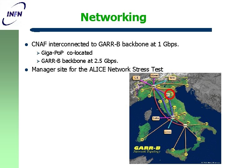
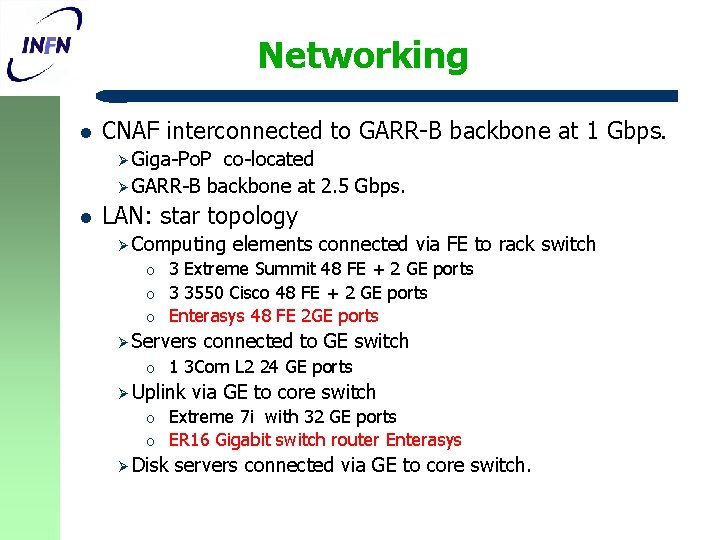
Networking l CNAF interconnected to GARR-B backbone at 1 Gbps. Ø Giga-Po. P co-located Ø GARR-B backbone at 2. 5 Gbps. l Manager site for the ALICE Network Stress Test
New Location l l CNAF upgrade for Tier 1 activity -> New Computing room The present location (at CNAF office level) is not suitable, mainly due to: Ø Insufficient space. Ø Weight (~ 700 kg. /0. 5 m 2 for a standard rack with 40 1 U servers). l Moving to the final location, within this month. Ø New hall in the basement (-2 nd floor) almost ready. Ø Easily accessible with lorries from the road Ø ~ 1000 m 2 of total space Ø Not suitable for office use (remote control)
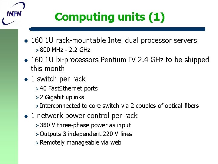
Computing units (1) l 160 1 U rack-mountable Intel dual processor servers Ø 800 l l MHz - 2. 2 GHz 160 1 U bi-processors Pentium IV 2. 4 GHz to be shipped this month 1 switch per rack Ø 40 Fast. Ethernet ports Ø 2 Gigabit uplinks Ø Interconnected to core switch via 2 couples of optical fibers l 1 network power control per rack Ø 380 V three-phase power as input Ø Outputs 3 independent 220 V lines Ø Remotely manageable via web
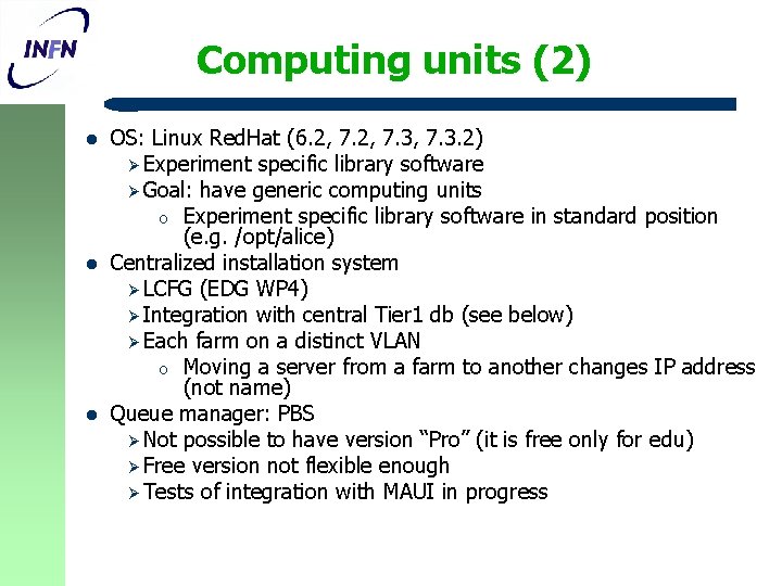
Computing units (2) l l l OS: Linux Red. Hat (6. 2, 7. 3, 7. 3. 2) Ø Experiment specific library software Ø Goal: have generic computing units o Experiment specific library software in standard position (e. g. /opt/alice) Centralized installation system Ø LCFG (EDG WP 4) Ø Integration with central Tier 1 db (see below) Ø Each farm on a distinct VLAN o Moving a server from a farm to another changes IP address (not name) Queue manager: PBS Ø Not possible to have version “Pro” (it is free only for edu) Ø Free version not flexible enough Ø Tests of integration with MAUI in progress
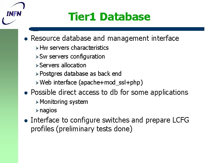
Tier 1 Database l Resource database and management interface Ø Hw servers characteristics Ø Sw servers configuration Ø Servers allocation Ø Postgres database as back end Ø Web interface (apache+mod_ssl+php) l Possible direct access to db for some applications Ø Monitoring system Ø nagios l Interface to configure switches and prepare LCFG profiles (preliminary tests done)
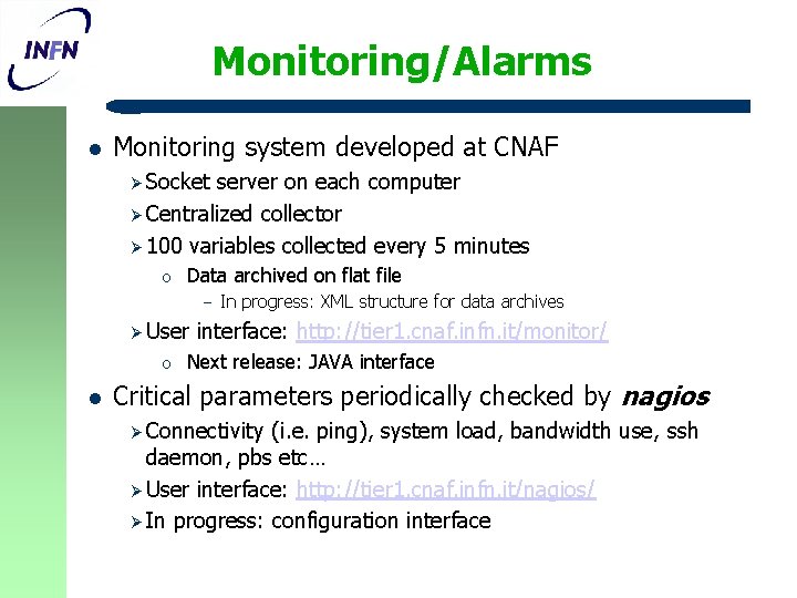
Monitoring/Alarms l Monitoring system developed at CNAF Ø Socket server on each computer Ø Centralized collector Ø 100 variables collected every 5 minutes o Data archived on flat file – Ø User o l In progress: XML structure for data archives interface: http: //tier 1. cnaf. infn. it/monitor/ Next release: JAVA interface Critical parameters periodically checked by nagios Ø Connectivity (i. e. ping), system load, bandwidth use, ssh daemon, pbs etc… Ø User interface: http: //tier 1. cnaf. infn. it/nagios/ Ø In progress: configuration interface
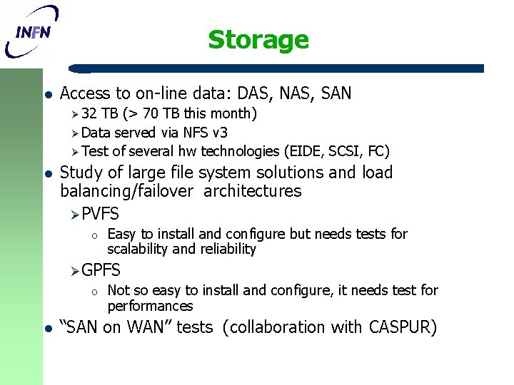
Storage l Access to on-line data: DAS, NAS, SAN Ø 32 TB (> 70 TB this month) Ø Data served via NFS v 3 Ø Test of several hw technologies (EIDE, SCSI, FC) l Study of large file system solutions and load balancing/failover architectures Ø PVFS o Easy to install and configure but needs tests for scalability and reliability Ø GPFS o l Not so easy to install and configure, it needs test for performances “SAN on WAN” tests (collaboration with CASPUR)
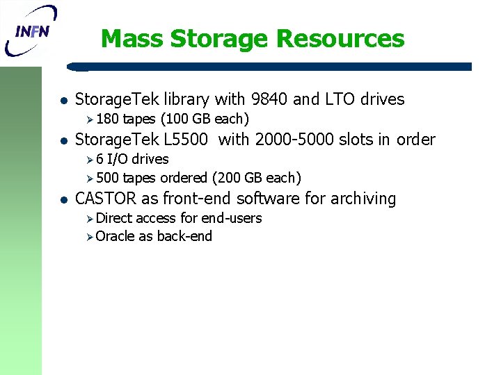
Mass Storage Resources l Storage. Tek library with 9840 and LTO drives Ø 180 l tapes (100 GB each) Storage. Tek L 5500 with 2000 -5000 slots in order Ø 6 I/O drives Ø 500 tapes ordered (200 GB each) l CASTOR as front-end software for archiving Ø Direct access for end-users Ø Oracle as back-end
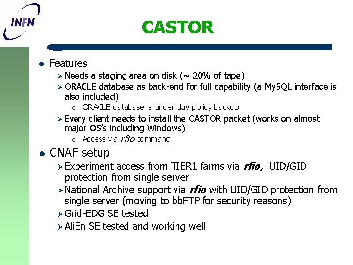
CASTOR l Features Ø Needs a staging area on disk (~ 20% of tape) Ø ORACLE database as back-end for full capability (a My. SQL interface is also included) o ORACLE database is under day-policy backup Ø Every client needs to install the CASTOR packet (works on almost major OS’s including Windows) o l Access via rfio command CNAF setup access from TIER 1 farms via rfio, UID/GID protection from single server Ø National Archive support via rfio with UID/GID protection from single server (moving to bb. FTP for security reasons) Ø Grid-EDG SE tested Ø Ali. En SE tested and working well Ø Experiment
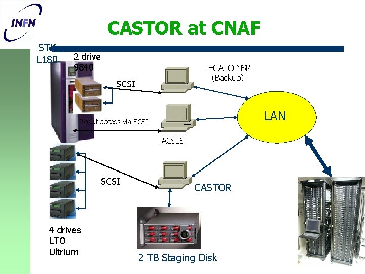
CASTOR at CNAF STK L 180 2 drive 9840 LEGATO NSR (Backup) SCSI LAN Robot access via SCSI ACSLS SCSI 4 drives LTO Ultrium CASTOR 2 TB Staging Disk
Present ALICE resources l l CPU: 6 worker nodes bi-processors 2. 4 GHz + 1 Ali. En server bi-processor 800 MHz (verificare). Some of ALICE CPU’s have been assigned to CMS for its DC Disk: 4. 2 TB, but only 800 GB used by Ali. En Tape: 2. 4 TB, used 1 TB. Computing and disk resources for 2004 at Italian Tier 1 and Tier 2’s (Catania and Torino) already submitted to the INFN referees. Feedback expected in a couple of weeks.
Summary & conclusions l INFN-TIER 1 is closing the prototype phase Ø But l l l still testing new technological solutions Moving the resources to the final location Starting integration with LCG We are waiting input for the preparation of the ADC 04
Networking l CNAF interconnected to GARR-B backbone at 1 Gbps. Ø Giga-Po. P co-located Ø GARR-B backbone at 2. 5 Gbps. l LAN: star topology Ø Computing o o o 3 Extreme Summit 48 FE + 2 GE ports 3 3550 Cisco 48 FE + 2 GE ports Enterasys 48 FE 2 GE ports Ø Servers o o connected to GE switch 1 3 Com L 2 24 GE ports Ø Uplink o elements connected via FE to rack switch via GE to core switch Extreme 7 i with 32 GE ports ER 16 Gigabit switch router Enterasys Ø Disk servers connected via GE to core switch.
GARR LAN CNAF 1 Gbps SSR 2000 Switch-lan. CNAF (*) Catalyst 6500 Farm. SWG 1 (*) LAN TIER 1 LHCBSW 1 (*) Farm. SW 3(*) Farm. SW 2(*) NAS 2 131. 154. 99. 192 NAS 3 131. 154. 99. 193 Fcds 1 Fcds 2 (*) vlan tagging enabled 1 Gbps link 8 T F. C. 2 T SCSI Fcds 3
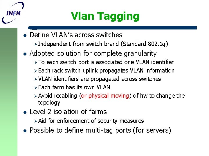
Vlan Tagging l Define VLAN’s across switches Ø Independent l from switch brand (Standard 802. 1 q) Adopted solution for complete granularity Ø To each switch port is associated one VLAN identifier Ø Each rack switch uplink propagates VLAN information Ø VLAN identifiers are propagated across switches Ø Each farm has its own VLAN Ø Avoid recabling (or physical moving) of hw to change the topology l Level 2 isolation of farms Ø Aid l for enforcement of security measures Possible to define multi-tag ports (for servers)
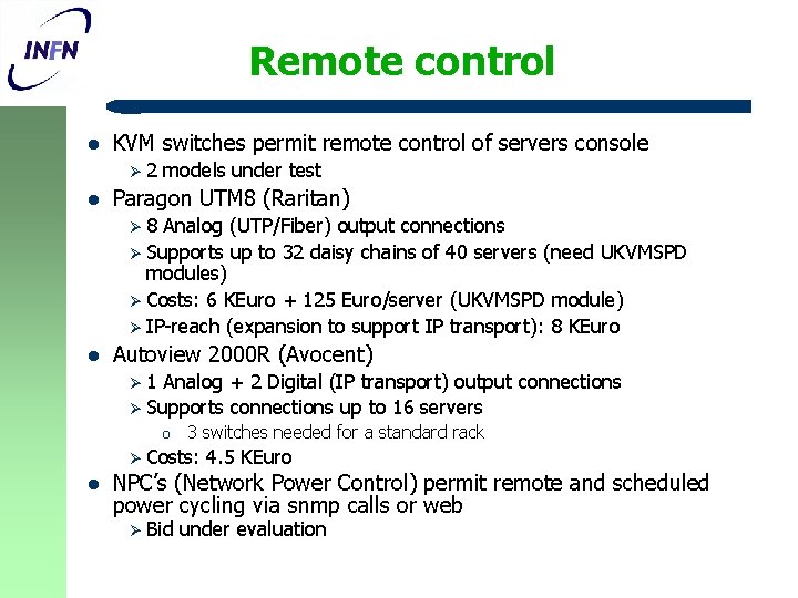
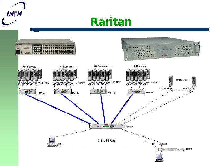
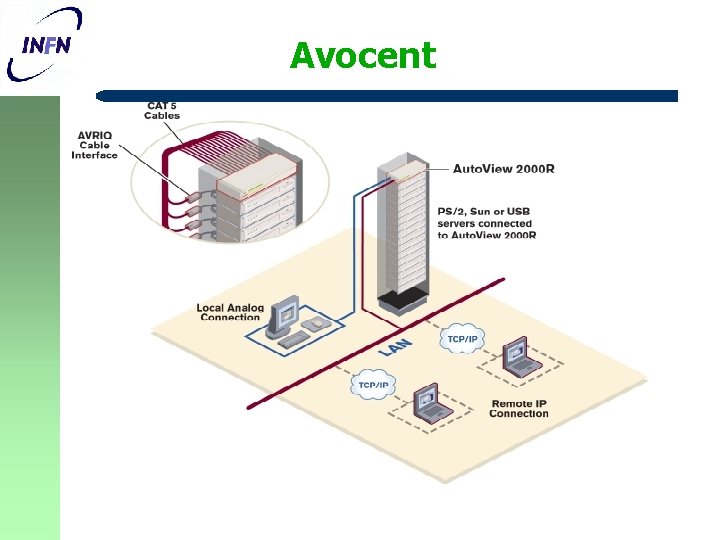
Remote control l KVM switches permit remote control of servers console Ø 2 l models under test Paragon UTM 8 (Raritan) Ø 8 Analog (UTP/Fiber) output connections Ø Supports up to 32 daisy chains of 40 servers (need UKVMSPD modules) Ø Costs: 6 KEuro + 125 Euro/server (UKVMSPD module) Ø IP-reach (expansion to support IP transport): 8 KEuro l Autoview 2000 R (Avocent) Ø 1 Analog + 2 Digital (IP transport) output connections Ø Supports connections up to 16 servers o 3 switches needed for a standard rack Ø Costs: l 4. 5 KEuro NPC’s (Network Power Control) permit remote and scheduled power cycling via snmp calls or web Ø Bid under evaluation
Raritan
Avocent
TAPE HARDWARE
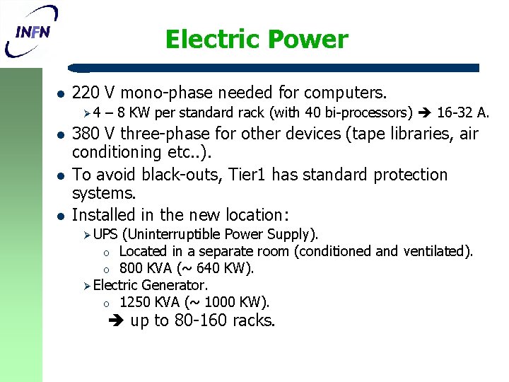
Electric Power l 220 V mono-phase needed for computers. Ø 4 l l l – 8 KW per standard rack (with 40 bi-processors) 16 -32 A. 380 V three-phase for other devices (tape libraries, air conditioning etc. . ). To avoid black-outs, Tier 1 has standard protection systems. Installed in the new location: Ø UPS (Uninterruptible Power Supply). o Located in a separate room (conditioned and ventilated). o 800 KVA (~ 640 KW). Ø Electric Generator. o 1250 KVA (~ 1000 KW). up to 80 -160 racks.
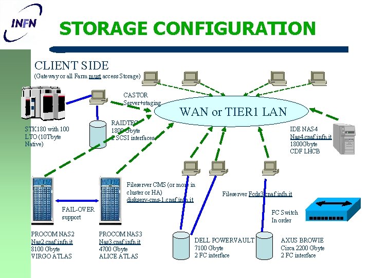
STORAGE CONFIGURATION CLIENT SIDE (Gateway or all Farm must access Storage) CASTOR Server+staging STK 180 with 100 LTO (10 Tbyte Native) WAN or TIER 1 LAN RAIDTEC 1800 Gbyte 2 SCSI interfaces IDE NAS 4 Nas 4. cnaf. infn. it 1800 Gbyte CDF LHCB Fileserver CMS (or more in cluster or HA) diskserv-cms-1. cnaf. infn. it Fileserver Fcds 3. cnaf. infn. it FAIL-OVER support PROCOM NAS 2 Nas 2. cnaf. infn. it 8100 Gbyte VIRGO ATLAS FC Switch In order PROCOM NAS 3 Nas 3. cnaf. infn. it 4700 Gbyte ALICE ATLAS DELL POWERVAULT 7100 Gbyte 2 FC interface AXUS BROWIE Circa 2200 Gbyte 2 FC interface