Three Phase Transformer When more power is needed


 power is delivered from generator with 3 separate")


 to")


 Wye")


- Slides: 20
Three Phase Transformer When more power is needed, three transformers can be tied together. This is called three-phase.
How much is it stronger? It is stronger by 173. 2 % = 1. 732 = √ 3
Two types of 3Ø transformer construction st 1 type NP 1 NS 1 NP 3 NP 2 NS 3 Three-phase transformer bank composed of 3 single phase independent transformers
nd 2 type Three phase transformer wound on a single three legged core NP 1 NS 1 NP 2 NS 2 NP 3 NS 3
Advantages of single 3Ø transformer over bank of 3 1Ø transformer • Occupies less floor space for equal rating • Less weight • Cheaper to maintain and connected
Generating three- phase Three phase (3Ø) power is delivered from generator with 3 separate windings. These windings are equally spaced, with 120º apart.
Three-phase voltages • Because three source voltages are timed at 3 different intervals, they can be transmitted over just 3 conductors. • If three-phase transformer bank we need 6 conductors to transmit 3 separate single-phase loads.
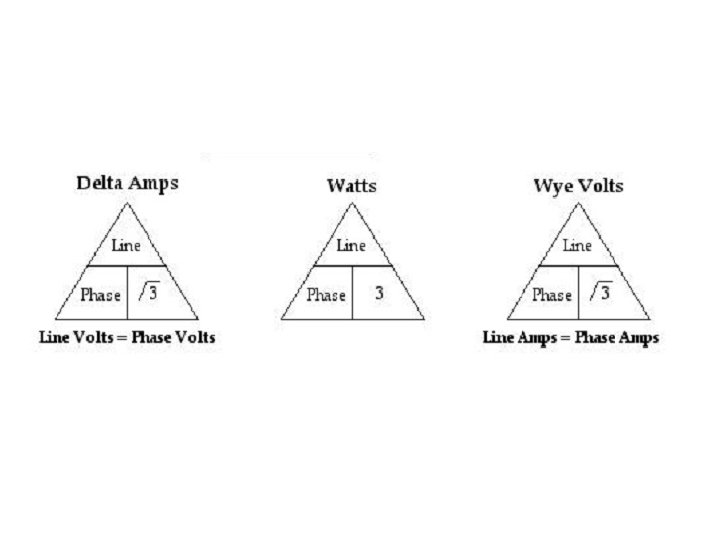
Multiply √ 3 We calculate the total voltage of all 3 line of a 3 phase transformer by multiplying the voltage of each single winding (phase) by √ 3. Why?
The reason is the angles of each phase are always 120º apart. By using trigonometric formula
How to tie 3 transformer together? Wye connection We call each single phase transformer windings “Phases”. • In parallel • (+) to (+) and (-) to (-) The combination we call “Line”.
Simplified Wye connection L 1 -L 2 120 V Advantage? 120 V Single-phase, 120 V fluorescent light Three-phase, 208 V heavy machine ? = Phase × √ 3 = 208 V , 1Ø L 2 –L 3 = Phase × √ 3 = 208 V, 1Ø L 3 –L 1 = Phase × √ 3 = 208 V, 1Ø L 1 - N L 2 - N L 3 - N Single -phase, 208 V oven = 120 V, 1Ø
How to tie 3 transformer together? Delta connection • In series • (+) to (-) They form a loop
Simplified Delta connection
Center tap
Types of Three- Phase Transformers 1. 2. 3. 4. Wye / Wye (Y-Y) Wye /Delta (Y-Δ) Delta -Wye (Δ-Y) Delta-Delta (Δ-Δ)
Wye-Wye Connection a a’ NP 1 b c NS 1 + VLP Vфp Vфs NS 2 - NP 3 Line Voltage b’ + NP 2 The overall voltage ratio is VLS c’ NS 3 n n a b + VLp Vфp Np 2 Np 3 c where a is the voltage ratio of each phase Vфs Np 1 Ns 2 Ns 1 Ns 3 a’ b’ + V Ls c’
Wye-Delta Connection a a’ NP 1 b + Vфp VLP c The overall voltage ratio is NS 1 b’ + NS 2 Vфs NP 2 - VLS NP 3 c’ NS 3 n a b + where a is the voltage ratio of each phase c’ Vфp Np 2 Ns 2 Np 1 + Ns 3 VLp b’ Np 3 Ns 1 c Vфs VLs a’
Delta-Wye Connection a VLP b + - + Vфp N - P 1 NS 1 a’ + + Vфs - c’ NP 2 VLS NS 2 c NP 3 The overall voltage ratio is b’ NS 3 n c + VLP + Vф. P NP 2 - NS 1 NP 3 b NP 1 a Vфs - + NS 2 a’ + VLS NS 3 b’ c’
Delta-Delta Connection a VLP b + Vфp - a’ NS 1 Vфs NP 1 VLs The overall voltage ratio is b’ NP 2 NS 2 c’ c NP 3 NS 3 a Ns 2 b c - Vфp V Lp NP 1 - +a’ + + - NP 2 NP 3 Ns 1 Ns 3 + Vфs V Ls - b’ c’