Three Phase Circuits Part2 Values of Phase Currents


 Line Currents and Phase Currents It is seen from Fig: 3 that each")


* or Mesh Connection Fig: 5")

 Line Voltages and Phase Voltages • It is seen from Fig: 5(b) that")
 Line Currents and Phase Currents • From Fig: 5…Current in line No. 1")


 is shown a Y-connected lighting network in a")

 Large k. VA for given amount of power • All electric machinery, like")
- Slides: 23
Three Phase Circuits Part-2
Values of Phase Currents • The arrow placed alongside the currents IR IY and IB flowing in the three phases [Fig: 1] indicate the directions of currents when they are assumed to be positive and not the directions at a particular instant. It should be clearly understood that at no instant will all the three currents flow in the same direction either outwards or inwards. The three arrows indicate that first the current flows outwards in phase R, then after a phase-time of 120°, it will flow outwards from phase Y and after a further 120°, outwards from phase B. • The current flowing outwards in one or two conductors is always equal to that flowing inwards in the remaining conductor or conductors. In other words, each conductor in turn, provides a return path for the currents of the other conductors. Fig: 1
• In Fig: 2 are shown the three phase currents, having the same peak value of 20 A but displaced from each other by 120°. At instant ‘a’, the currents in phases R and B are each + 10 A (i. e. flowing outwards) whereas the current in phase Y is – 20 A (i. e. flowing inwards). In other words, at the instant ‘a’, phase Y is acting as return path for the currents in phases R and B. At instant b, IR = +15 A and IY = +5 A but IB = – 20 A which means that now phase B is providing the return path. Fig: 2 • At instant c, IY = +15 A and IB = +5 A and IR = – 20 A. • Hence, now phase R carries current inwards whereas Y and B carry current outwards. Similarly at point d, IR = 0, IB = 17. 3 A and IY = – 17. 3 A. In other words, current is flowing outwards from phase B and returning via phase Y. • In addition, it may be noted that although the distribution of currents between the three lines is continuously changing, yet at any instant the algebraic sum of the instantaneous values of the three currents is zero i. e. IR + IY + IB = 0
Voltages and Currents in Y-Connection Fig: 3 • The voltage induced in each winding is called the phase voltage and current in each winding is likewise known as phase current. However, the voltage available between any pair of terminals (or outers) is called line voltage (VL) and the current flowing in each line is called line current (IL ). • As seen from Fig: 3, in this form of interconnection, there are two phase windings between each pair of terminals but since their similar ends have been joined together, they are in opposition.
• Obviously, the instantaneous value of p. d. between any two terminals is the arithmetic difference of the two phase e. m. fs. concerned. However, the r. m. s. value of this p. d. is given by the vector difference of the two phase e. m. fs. The vector diagram for phase voltages and currents in a star connection is shown in Fig: 3. • where a balanced system has been assumed. * It means that ER = EY = Eph (phase e. m. f. ). • Line voltage VRY between line 1 and line 2 is the vector difference of ER and EY. • Line voltage VYB between line 2 and line 3 is the vector difference of EY and EB. • Line voltage VBR between and line 1 is the vector difference of EB and ER. (a) Line Voltages and Phase Voltages • The p. d. between line 1 and 2 is VRY = ER – EY. . . vector difference. • Hence, VRY is found by compounding ER and EY reversed and its value is given by the diagonal of the parallelogram of Fig. 19. 13. Obviously, the angle between ER and EY reversed is 60°. Hence if ER = EY = EB = say, Eph – the phase e. m. f. , then Fig: 4
• It will be noted from Fig: 4 that 1. Line voltages are 120° apart. 2. Line voltages are 30° ahead of their respective phase voltages. 3. The angle between the line currents and the corresponding line voltages is (30 + φ ) with current lagging.
(b) Line Currents and Phase Currents It is seen from Fig: 3 that each line is in series with its individual phase winding, hence the line current in each line is the same as the current in the phase winding to which the line is connected. Current in line 1 = IR ; Current in line 2 = IY; Current in line 3 = IB Since IR = IY = IB = say, Iph – the phase current ∴ line current IL = Iph (c) Power The total active or true power in the circuit is the sum of the three phase powers.
Example: 1
Example: 2
Example: 3
Delta (Δ)* or Mesh Connection Fig: 5
• In this form, of interconnection the dissimilar ends of the three phase winding are joined together i. e. the ‘starting’ end of one phase is joined to the ‘finishing’ end of the other phase and so on as showing in Fig: 5(a). • In other words, the three windings are joined in series to form a closed mesh as shown in Fig: 5(b). • Three leads are taken out from the three junctions as shown as outward directions are taken as positive. • It might look as if this sort of interconnection results in Fig: 4 and Fig: 5 As an aid to memory, remember that first letter D of Dissimilar is the same as that of Delta. 680 Electrical Technology short circuiting the three windings. • However, if the system is balanced then sum of the three voltages round the closed mesh is zero, hence no current of fundamental frequency can flow around the mesh when the terminals are open. • It should be clearly understood that at any instant, the e. m. f. in one phase is equal and opposite to the resultant of those in the other two phases. This type of connection is also referred to as 3 -phase, 3 -wire system.
(i) Line Voltages and Phase Voltages • It is seen from Fig: 5(b) that there is only one phase winding completely included between any pair of terminals. • Hence, in Δ-connection, the voltage between any pair of lines is equal to the phase voltage of the phase winding connected between the two lines considered. • Since phase sequence is R Y B, the voltage having its positive direction from R to Y leads by 120° on that having its positive direction from Y to B. • Calling the voltage between lines 1 and 2 as VRY and that between lines 2 and 3 as VYB, we find that VRY lead VYB by 120°. Similarly, VYB leads VBR by 120º as shown in Fig: 4. • Let VRY = VYB = VBR = line voltage VL. Then, it is seen that VL = Vph.
(ii) Line Currents and Phase Currents • From Fig: 5…Current in line No. 1 is found by compounding IR and IB reversed and its value is given by the diagonal of the parallelogram of Fig. 19. 25. The angle between IR and IB reversed (i. e. – IB) is 60°. If IR = IY = phase current Iph (say), then Fig: 6
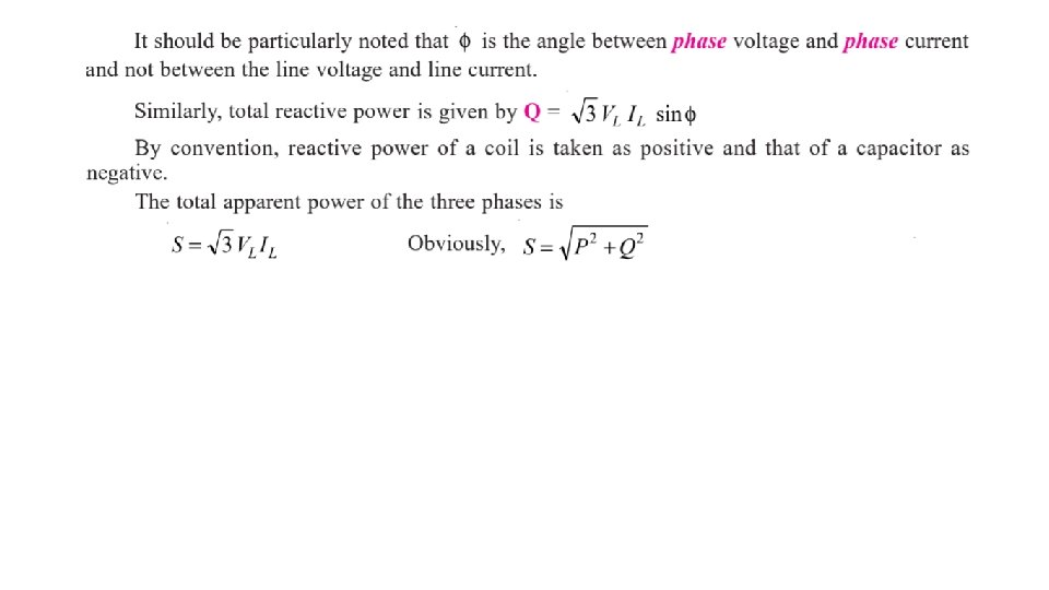
• With reference to Fig: 6, it should be noted that 1. line currents are 120º apart ; 2. line currents are 30º behind the respective phase currents ; 3. the angle between the line currents and the corresponding line voltages is (30 + φ ) with the current lagging. (iii) Power
Balanced Y/Δ and Δ/Y Conversion • Fig: 7
• Similarly, a balanced Y-connected load having equal branch impedances each of Z ∠ φ may be replaced by an equivalent Δconnected load whose each phase impedance is 3 Z ∠ φ. This equivalence is shown in Fig: 7.
Example: 4
Star and Delta connected Lighting Loads Fig: 8
• In Fig: 8 (a) is shown a Y-connected lighting network in a three storey house. For such a load, it is essential to have neutral wire in order to ensure uniform distribution of load among the three phases despite random switching on and off or burning of lamps. • It is seen from Fig: 8 (a), that network supplies two flats on each floor of the three storey residence and there is balanced distribution of lamp load among the three phases. • There are house fuses at the cable entry into the building which protect the two mains against short-circuits in the main cable. At the flat entry, there apartment (or flat) fuses in the single-phase supply which protect the two mains and other flats in the same building from short-circuits in a given building. • There is no fuse (or switch) on the neutral wire of the mains because blowing of such a fuse (or disconnection of such a switch) would mean a break in the neutral wire. • This would result in unequal voltages across different groups of lamps in case they have different power ratings or number. • Consequently, filaments in one group would burn dim whereas in other groups they would burn too bright resulting in their early burn-out. The house-lighting wire circuit for Δ-connected lamps is shown in Fig: 8(b).
Power Factor Improvement • The heating and lighting loads supplied from 3 -phase supply have power factors, ranging from 0. 95 to unity. But motor loads have usually low lagging power factors, ranging from 0. 5 to 0. 9. Single-phase motors may have as low power factor as 0. 4 and electric wedding units have even lower power factors of 0. 2 or 0. 3. • In each case, the k. VA is directly proportional to current. The chief disadvantage of a low p. f. is that the current required for a given power, is very high. This fact leads to the following undesirable results
(i) Large k. VA for given amount of power • All electric machinery, like alternators, transformers, switchgears and cables are limited in their current-carrying capacity by the permissible temperature rise, which is proportional to I 2. • Hence, they may all be fully loaded with respect to their rated k. VA, without delivering their full power. • Obviously, it is possible for an existing plant of a given k. VA rating to increase its earning capacity (which is proportional to the power supplied in k. W) if the overall power factor is improved i. e. raised. (ii) Poor voltage regulation • When a load, having allow lagging power factor, is switched on, there is a large voltage drop in the supply voltage because of the increased voltage drop in the supply lines and transformers. • This drop in voltage adversely affects the starting torques of motors and necessitates expensive voltage stabilizing equipment for keeping the consumer’s voltage fluctuations within the statutory limits. • Moreover, due to this excessive drop, heaters take longer time to provide the desired heat energy, fluorescent lights flicker and incandescent lamps are not as bright as they should be. • Hence, all supply undertakings try to encourage consumers to have a high power factor.