THREE PHASE CIRCUITS Generation of Three Phase Fig


 Connection Fig: 9")
- Slides: 12
THREE PHASE CIRCUITS
Generation of Three Phase • Fig: 1 illustrates the relative positions of the windings of a 3 -phase, 4 -pole alternator and Fig: 2 shows the developed diagram of its armature windings. • Assuming full-pitched winding and the direction of rotation as shown, phase ‘a’ occupies the position under the centres of N and S-poles. • It starts at Sa and ends or finishes at Fa. • The second phase ‘b’ start at Sb which is 120 electrical degrees apart from the start of phase ‘a’, progresses round the armature clockwise (as does ‘a’) and finishes at Fb. • Similarly, phase ‘c’ starts at Sc, which is 120 electrical degrees away from Sb, progresses round the armature and finishes at Fc. Fig: 1 Fig: 2
Fig: 3 • The sum of ordinates of three e. m. f. curves of Fig. 3 is zero. For example, taking ordinates AB and AC as positive and AD as negative, it can be shown by actual measurement that • AB + AC + (– AD) = 0 • If we add the three vectors of Fig. 4 either vectorially or by calculation, the result is zero.
Vector Diagram Fig: 4 Fig: 5
Phase Sequence • By phase sequence is meant the order in which the three phases attain their peak or maximum values. • In the development of the three-phase e. m. fs. in Figure clockwise rotation of the field system in Figure: 1 was assumed. • This assumption made the e. m. fs. of phase ‘b’ lag behind that of ‘a’ by 120° and in a similar way, made that of ‘c’ lag behind that of ‘b’ by 120° (or that of ‘a’ by 240°). • Hence, the order in which the e. m. fs. of phases a, b and c attain their maximum values is a b c. It is called the phase order or phase sequence abc → → as illustrated in Fig. 6 (a). Fig: 6
• If, now, the rotation of the field structure of Fig. 1 is reversed i. e. made anticlockwise, then the order in which the three phases would attain their corresponding maximum voltages would also be reversed. • This means that e. m. f. of phase ‘c’ would now lag behind that of phase ‘a’ by 120° instead of 240°
Phase Sequence at Load • The phase sequence can be reversed by interchanging any pair of lines. • In the case of an induction motor, reversal of sequence results in the reversed direction of motor rotation. • In the case of 3 -phase unbalanced loads, the effect of sequence reversal is, in general, to cause a completely different set of values of the currents. • Hence, when working on such systems, it is essential that phase sequence be clearly specified otherwise unnecessary confusion will arise. • Incidentally, reversing the phase sequence of a 3 -phase generator which is to be paralleled with a similar generator can cause extensive damage to both the machines. Fig: 7
• Fig. 7 illustrates the fact that by interchanging any two of the three cables the phase sequence at the load can be reversed though sequence of 3 -phase supply remains the same i. e. abc. • It is customary to define phase sequence at the load by reading repetitively from top to bottom. • For example, load phase sequence in Fig. 7 would be read as abcabcabc – or simply abc. The changes are as tabulated below :
Numbering of Phase • The three phases may be numbered 1, 2, 3 or a, b, c or as is customary, they may be given three colours. • The colours used commercially are red, yellow (or sometimes white) and blue. In this case, the sequence is RYB. • Obviously, in any three-phase system, there are two possible sequences in which the three coil or phase voltages may pass through their maximum values i. e. red → yellow → blue (RYB) or red → blue → yellow (RBY). • By convention, RYB sequence is taken as positive and RBY as negative.
Interconnection of Three Phases • If the three armature coils of the 3 -phase alternator (Fig. 7) are not interconnected but are kept separate, as shown in Fig. 8, then each phase or circuit would need two conductors, the total number of conductors, in that case, being six. • It means that each transmission cable would contain six conductors which will make the whole system complicated and expensive. • Hence, the three phases are generally interconnected which results in substantial saving of copper. • The general methods of interconnection are • (a) Star or Wye (Y) connection and (b) Mesh or Delta ( Δ ) connection. Fig: 8
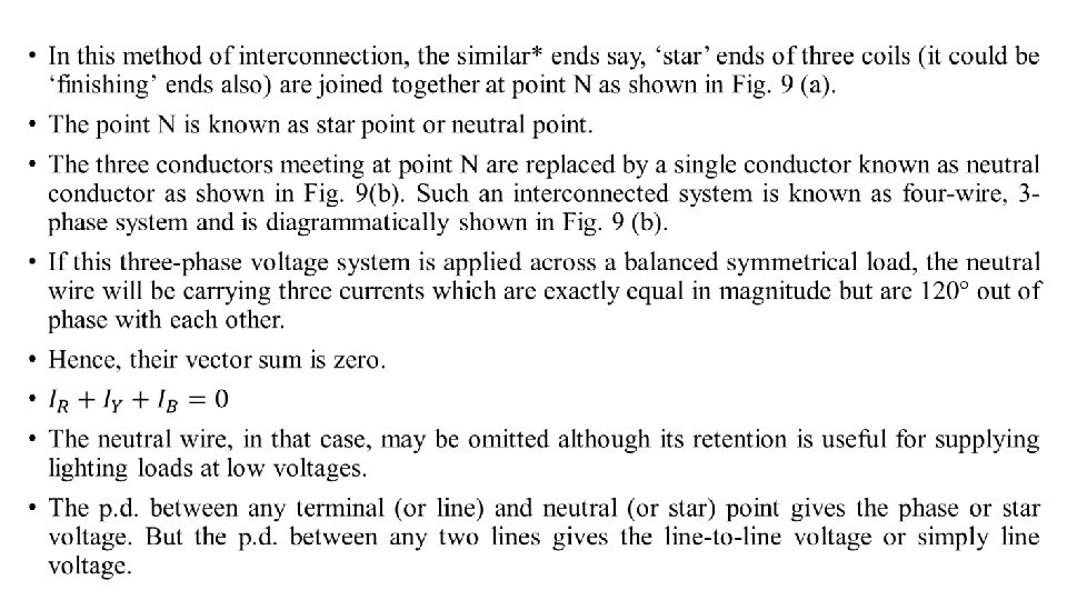
Star or Wye (Y) Connection Fig: 9