
Thomas Alva Edison 1847 1931 Nikola Tesla 1856
- Slides: 24
Thomas Alva Edison (1847 – 1931) Nikola Tesla (1856 – 1943) Electricity & Electronics Bruce E. Amrein, MES, MBA, CTS 1 Igniting the Spark of Science!
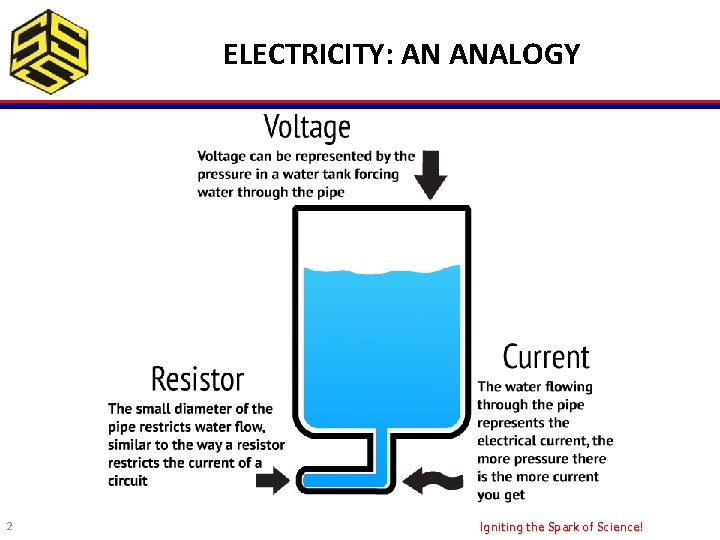
ELECTRICITY: AN ANALOGY 2 Igniting the Spark of Science!
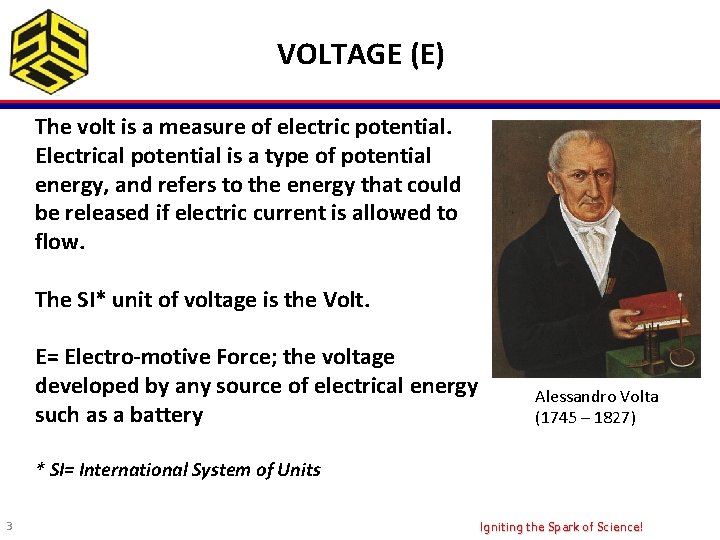
VOLTAGE (E) The volt is a measure of electric potential. Electrical potential is a type of potential energy, and refers to the energy that could be released if electric current is allowed to flow. The SI* unit of voltage is the Volt. E= Electro-motive Force; the voltage developed by any source of electrical energy such as a battery Alessandro Volta (1745 – 1827) * SI= International System of Units 3 Igniting the Spark of Science!
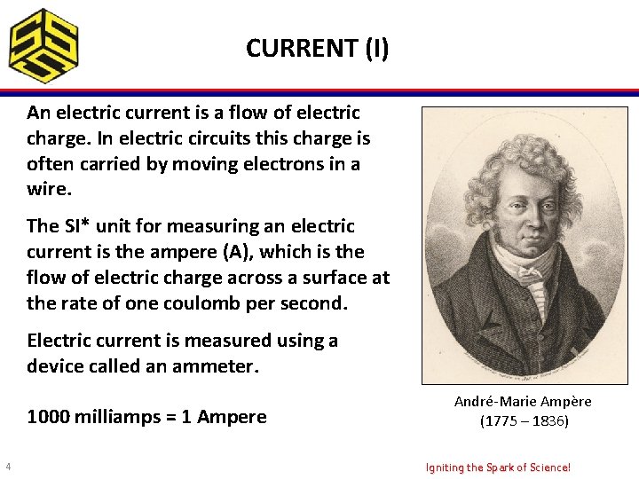
CURRENT (I) An electric current is a flow of electric charge. In electric circuits this charge is often carried by moving electrons in a wire. The SI* unit for measuring an electric current is the ampere (A), which is the flow of electric charge across a surface at the rate of one coulomb per second. Electric current is measured using a device called an ammeter. 1000 milliamps = 1 Ampere 4 André-Marie Ampère (1775 – 1836) Igniting the Spark of Science!
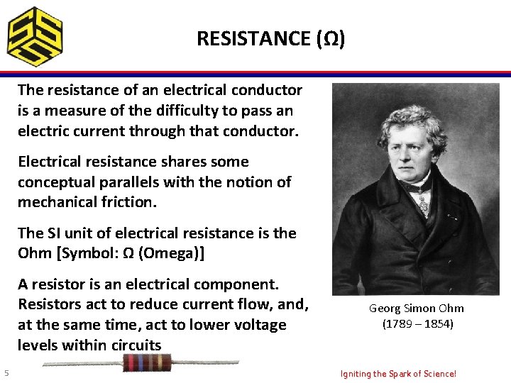
RESISTANCE (Ω) The resistance of an electrical conductor is a measure of the difficulty to pass an electric current through that conductor. Electrical resistance shares some conceptual parallels with the notion of mechanical friction. The SI unit of electrical resistance is the Ohm [Symbol: Ω (Omega)] A resistor is an electrical component. Resistors act to reduce current flow, and, at the same time, act to lower voltage levels within circuits 5 Georg Simon Ohm (1789 – 1854) Igniting the Spark of Science!
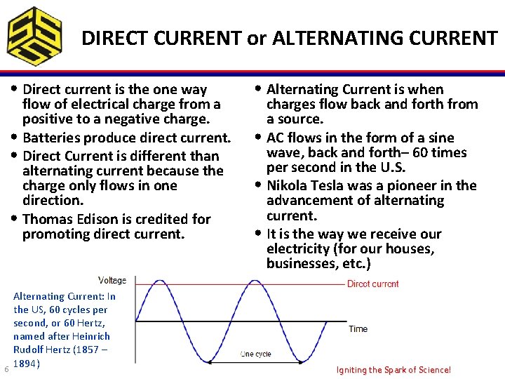
DIRECT CURRENT or ALTERNATING CURRENT • Direct current is the one way flow of electrical charge from a positive to a negative charge. • Batteries produce direct current. • Direct Current is different than alternating current because the charge only flows in one direction. • Thomas Edison is credited for promoting direct current. 6 Alternating Current: In the US, 60 cycles per second, or 60 Hertz, named after Heinrich Rudolf Hertz (1857 – 1894) • Alternating Current is when charges flow back and forth from a source. • AC flows in the form of a sine wave, back and forth– 60 times per second in the U. S. • Nikola Tesla was a pioneer in the advancement of alternating current. • It is the way we receive our electricity (for our houses, businesses, etc. ) Igniting the Spark of Science!
SYMBOLOGY & NOTATION • Voltage, symbolized by the letters “E” or “V”; measured in volts. • Current, symbolized by the letter “I”; measured in amps– short for amperes. • Small currents, symbolized by the letter “I”; measured in milliamps (1/1000 th of an amp). • Resistance, symbolized by the letter “R”, measured in ohms (Ω). 7 Igniting the Spark of Science!
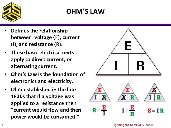
OHM’S LAW • Defines the relationship between voltage (E), current (I), and resistance (R). • These basic electrical units apply to direct current, or alternating current. • Ohm’s Law is the foundation of electronics and electricity. • Ohm established in the late 1820 s that if a voltage was applied to a resistance then “current would flow and then power would be consumed. ” 8 Igniting the Spark of Science!
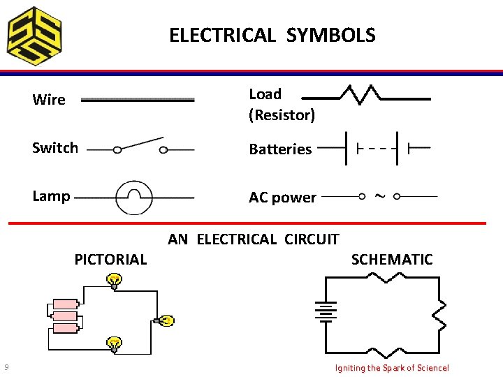
ELECTRICAL SYMBOLS Wire Load (Resistor) Switch Batteries Lamp AC power PICTORIAL 9 AN ELECTRICAL CIRCUIT SCHEMATIC Igniting the Spark of Science!
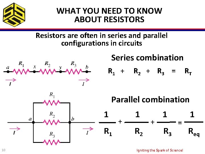
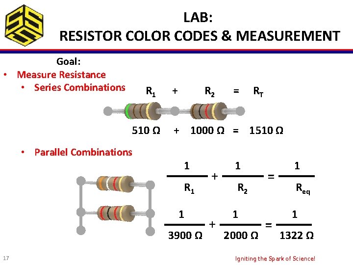
WHAT YOU NEED TO KNOW ABOUT RESISTORS Resistors are often in series and parallel configurations in circuits Series combination R 1 + R 2 + R 3 = RT Parallel combination 1 R 1 10 + 1 R 2 + 1 R 3 = Igniting the Spark of Science! 1 Req
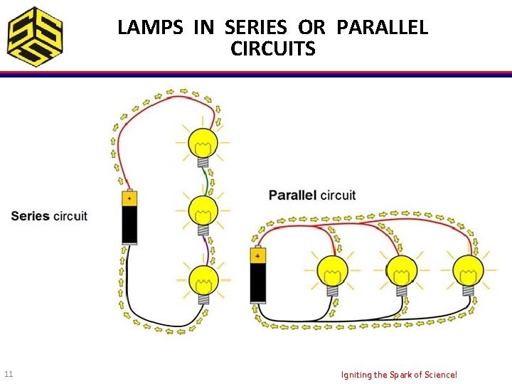
LAMPS IN SERIES OR PARALLEL CIRCUITS 11 Igniting the Spark of Science!
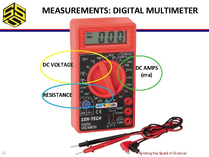
MEASUREMENTS: DIGITAL MULTIMETER DC VOLTAGE DC AMPS (ma) RESISTANCE 12 Igniting the Spark of Science!
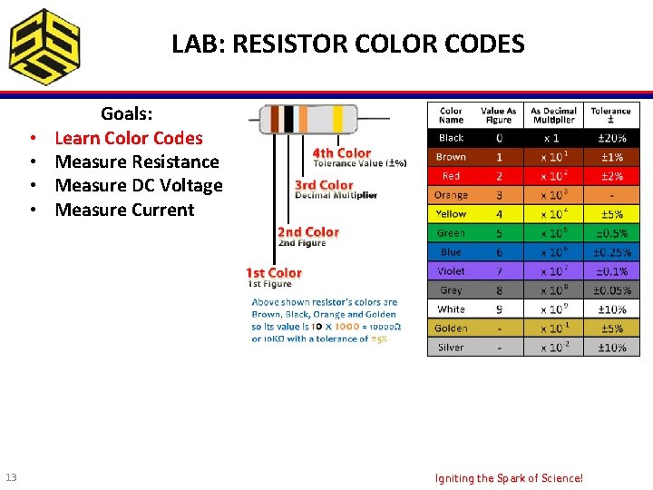
LAB: RESISTOR COLOR CODES • • 13 Goals: Learn Color Codes Measure Resistance Measure DC Voltage Measure Current Igniting the Spark of Science!
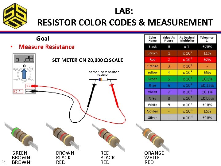
LAB: RESISTOR COLOR CODES & MEASUREMENT Goal • Measure Resistance Ω 14 GREEN BROWN SET METER ON 20, 000 Ω SCALE BROWN BLACK RED ORANGE WHITE Igniting the Spark of Science! RED
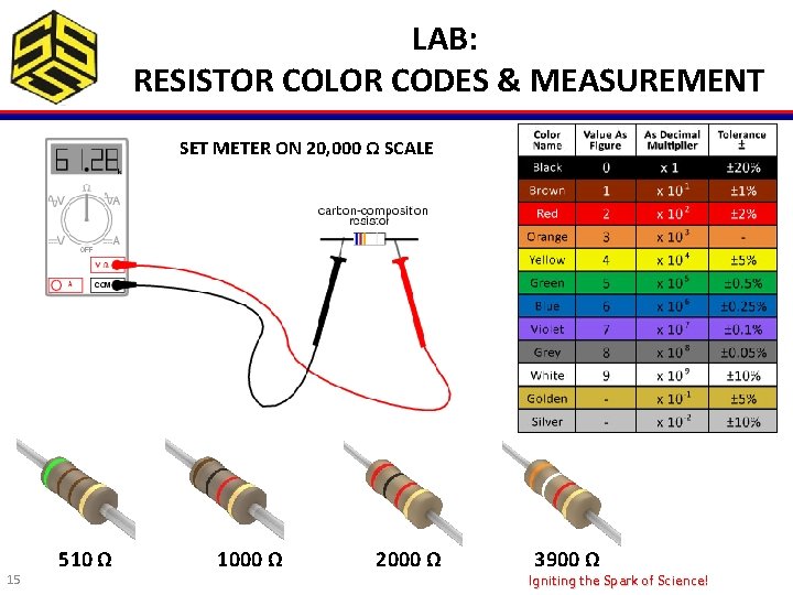
LAB: RESISTOR COLOR CODES & MEASUREMENT SET METER ON 20, 000 Ω SCALE 15 510 Ω 1000 Ω 2000 Ω 3900 Ω Igniting the Spark of Science!
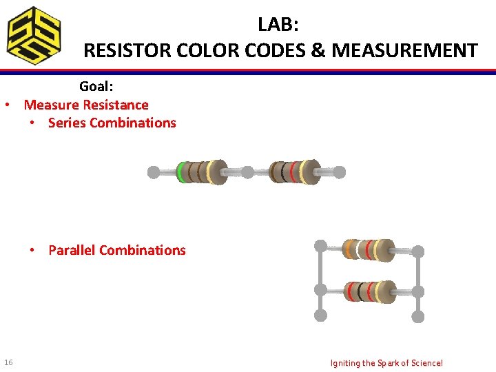
LAB: RESISTOR COLOR CODES & MEASUREMENT Goal: • Measure Resistance • Series Combinations • Parallel Combinations 16 Igniting the Spark of Science!
LAB: RESISTOR COLOR CODES & MEASUREMENT Goal: • Measure Resistance • Series Combinations R 1 510 Ω • Parallel Combinations + R 2 RT + 1000 Ω = 1510 Ω 1 R 1 1 3900 Ω 17 = + + 1 R 2 1 2000 Ω = = 1 Req 1 1322 Ω Igniting the Spark of Science!
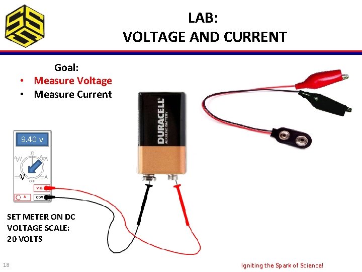
LAB: VOLTAGE AND CURRENT Goal: • Measure Voltage • Measure Current 9. 40 v V SET METER ON DC VOLTAGE SCALE: 20 VOLTS 18 Igniting the Spark of Science!
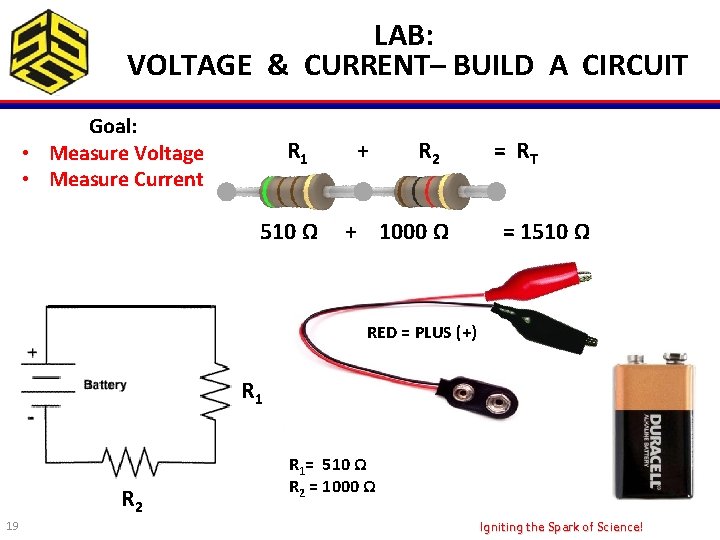
LAB: VOLTAGE & CURRENT– BUILD A CIRCUIT Goal: • Measure Voltage • Measure Current R 1 510 Ω + R 2 + 1000 Ω = RT = 1510 Ω RED = PLUS (+) R 1 R 2 19 R 1= 510 Ω R 2 = 1000 Ω Igniting the Spark of Science!
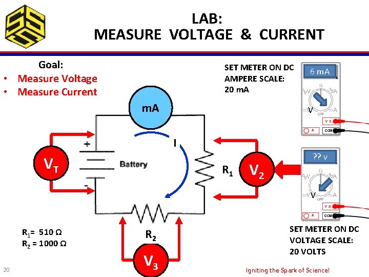
LAB: MEASURE VOLTAGE & CURRENT Goal: • Measure Voltage • Measure Current SET METER ON DC AMPERE SCALE: 20 m. A 6 m. A V I VT R 1 V 2 ? ? v V R 1= 510 Ω R 2 = 1000 Ω 20 R 2 V 3 SET METER ON DC VOLTAGE SCALE: 20 VOLTS Igniting the Spark of Science!
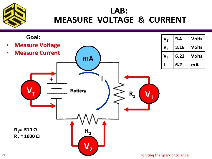
LAB: MEASURE VOLTAGE & CURRENT Goal: • Measure Voltage • Measure Current m. A VT 9. 4 Volts V 1 3. 18 Volts V 2 6. 22 Volts I 6. 2 m. A I VT R 1= 510 Ω R 2 = 1000 Ω 21 R 1 V 1 R 2 V 2 Igniting the Spark of Science!
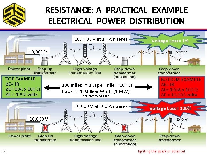
RESISTANCE: A PRACTICAL EXAMPLE ELECTRICAL POWER DISTRIBUTION 100, 000 V at 10 Amperes Voltage Loss= 1% 10, 000 V TOP EXAMPLE ΔE= IR ΔE= 10 A x 100 Ω ΔE = 1000 volts 100 miles @ 1 Ω per mile = 100 Ω Power = 1 Million Watts (1 MW) Wire= #3 AWG Copper 10, 000 V at 100 Amperes BOTTOM EXAMPLE ΔE= IR ΔE= 100 A x 100 Ω ΔE = 10, 000 volts Voltage Loss= 100% 10, 000 V X 22 X Igniting the Spark of Science!
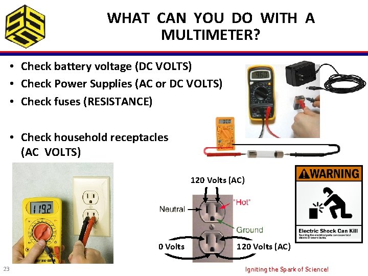
WHAT CAN YOU DO WITH A MULTIMETER? • Check battery voltage (DC VOLTS) • Check Power Supplies (AC or DC VOLTS) • Check fuses (RESISTANCE) • Check household receptacles (AC VOLTS) 120 Volts (AC) 0 Volts 23 120 Volts (AC) Igniting the Spark of Science!
Thank you! Are there any questions? 24 Igniting the Spark of Science!