
Things that Happened Before You were Born The

Things that Happened Before You were Born (The earth and SWMM were created) a story by Dr. Larry A. Roesner, Ph. D. , P. E. based (loosely*) on biblical quotes and his own bigger than life experiences *Actually very loosely
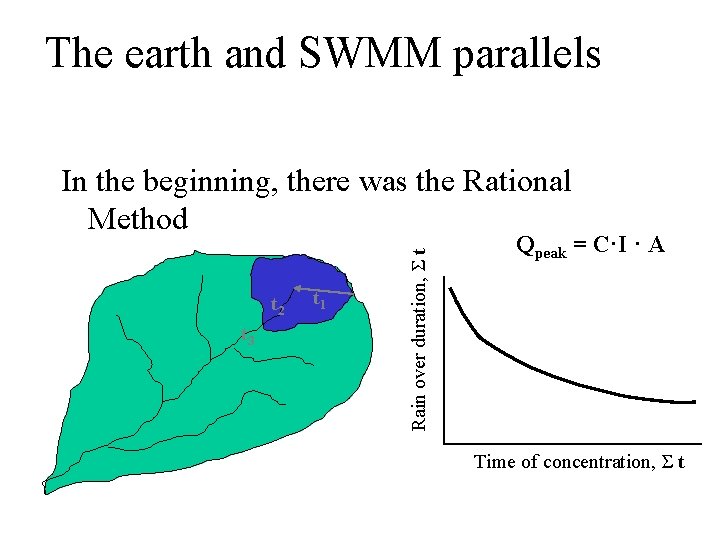
The earth and SWMM parallels t 2 t 3 t 1 Rain over duration, Σ t In the beginning, there was the Rational Method Qpeak = C·I · A Time of concentration, Σ t
The earth and SWMM parallels And darkness covered the drainage world because of the limited applicability of the Rational Method
The earth and SWMM parallels Then forward looking engineers said “let there be light” And so, they created more rational models n. SCS TR 20 and TR 55 n. HEC-1, 2, 3, 4, 5, 6, and RAS n. SWMM
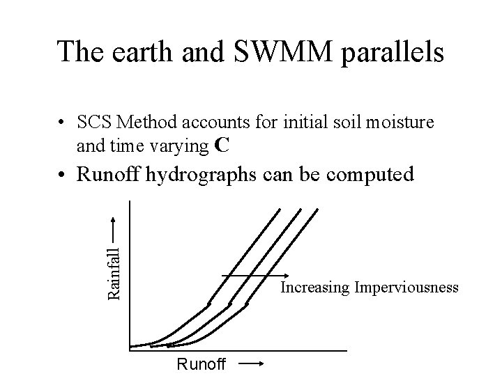
The earth and SWMM parallels • SCS Method accounts for initial soil moisture and time varying C Rainfall • Runoff hydrographs can be computed Increasing Imperviousness Runoff
The earth and SWMM parallels • HEC model produces runoff hydrograph from rainfall hyetograph using unit hydrograph technique (Who knows the Schneider coefficient for a 30% pervious urban area? ) • Hydrologic routing produces channel flows • Hec 2 computes steady state backwater through maximum discharge profile
The earth and SWMM parallels • SWMM was to be the mother of all models • It would trace runoff from its point of origin, through the stormwater system to and through the receiving waters, computing flows and water levels • It would trace wet weather pollution from its point of origin to its final fate in the receiving waters
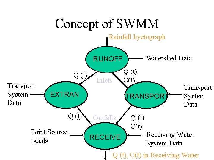
Concept of SWMM Rainfall hyetograph Watershed Data RUNOFF Q (t) Transport System Data Q (t) C(t) Inlets EXTRAN Q (t) Point Source Loads TRANSPORT Outfalls RECEIVE Transport System Data Q (t) C(t) Receiving Water System Data Q (t), C(t) in Receiving Water
The earth and SWMM parallels And so it was, and (most) Civil Engineers saw the models and they were good. And so they rested, for 30 yrs!!?
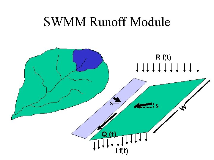
SWMM Runoff Module R f(t) S S Q (t) I f(t) W
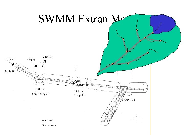
SWMM Extran Module

INTRODUCTION TO SWMM AND MIKE SWMM CE 580 Analysis of Urban Water Systems Dr Larry Roesner, Colorado State University
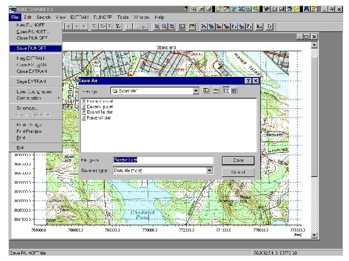
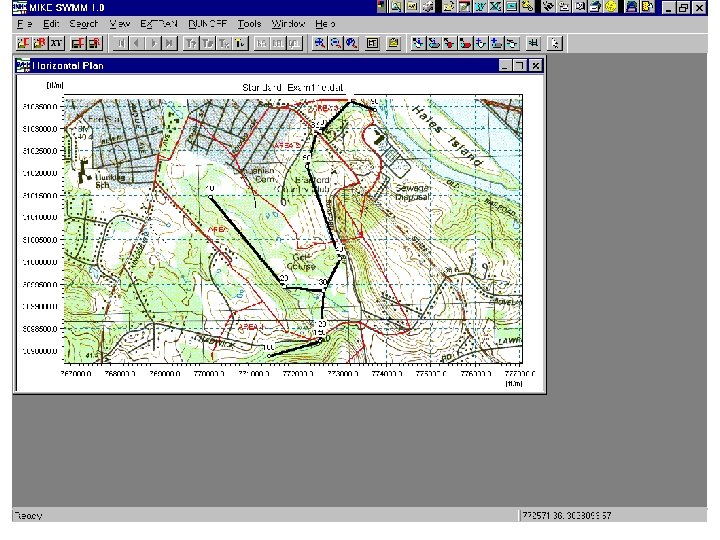
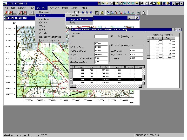
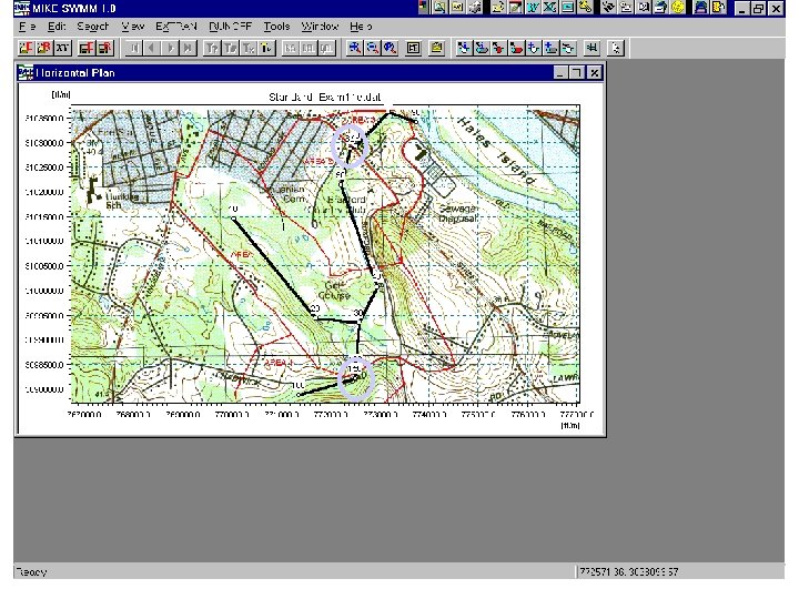
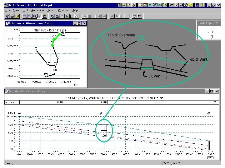
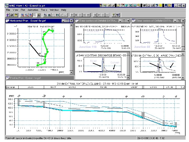
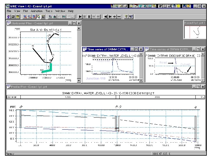
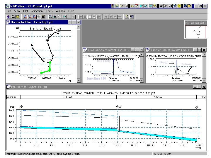
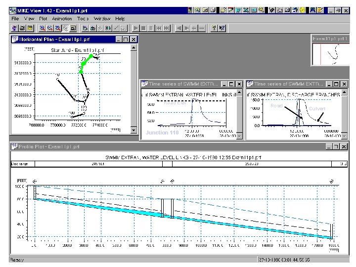
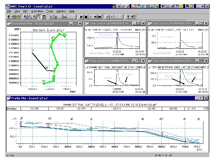
This presentation is an embellishment of the road culvert example contained in the Mike SWMM documentation. In order to see the results of road overtopping, the weirs at nodes 110 and 60 have been changed to box conduits. Three simuations were performed: o The "existing" condition: File name Exam 11 e. dat - culvert 110 diameter = 1. 0 ft - culvert 60 diameter = 3. 0 ft o The "existing" condition: File name Exam 11 p 1. dat - culvert 110 diameter = 2. 0 ft - culvert 60 diameter = 3. 5 ft o The "existing" condition: File name Exam 11 p 2. dat - culvert 110 diameter = 4. 0 ft - culvert 60 diameter = 5. 0 ft The first simulation shows severe overtopping of the road at both location, with prolonged backwater at junction 110. The second simulation shows much improvement, and the third simulation shows the problem fixed except for a small 15 minute overtopping of the road at junction 110. Modifications by LAR 12/2/98

. . . o w t f o r e w o p e Th Camp Dresser & Mc. Kee Danish Hydraulic Institute

Danish Hydraulic Institute - a Consulting and Research Organization • Objectives: – to develop and apply advanced methods and technologies • within hydraulic and hydrological engineering – to provide specialised consulting services – to contribute to the technological development through • international research collaboration and through • transfer of know-how and technology
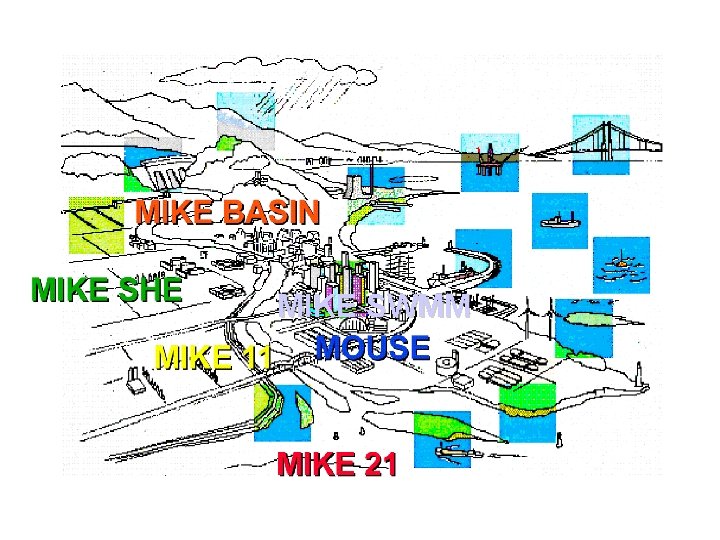
MIKE SWMM
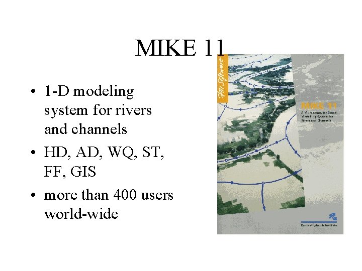
MIKE 11 • 1 -D modeling system for rivers and channels • HD, AD, WQ, ST, FF, GIS • more than 400 users world-wide
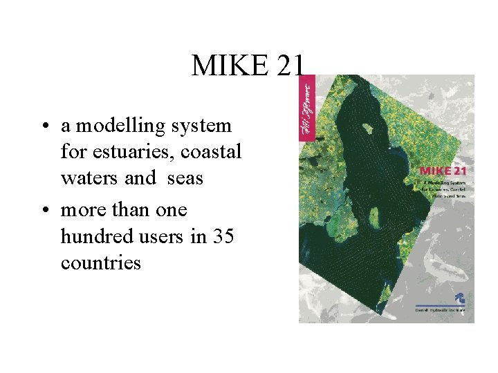
MIKE 21 • a modelling system for estuaries, coastal waters and seas • more than one hundred users in 35 countries
MIKE SHE • an integrated hydrological modeling system • 3 -D Groundwater movement, unsaturated zone, Solute transport, dynamic link to MIKE 11 • some 50 users in 10 countries
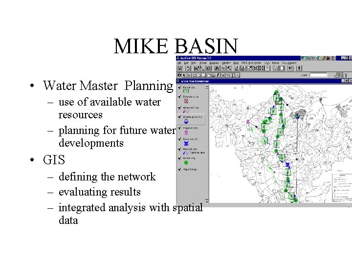
MIKE BASIN • Water Master Planning – use of available water resources – planning for future water developments • GIS – defining the network – evaluating results – integrated analysis with spatial data
LITPACK • an integrated modelling system for Littoral Processes And Coastline Kinetics • more than 60 users in 20 countries
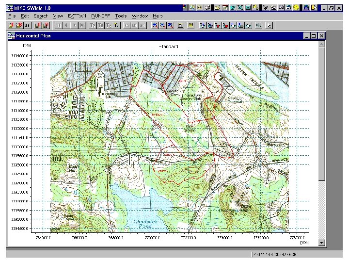
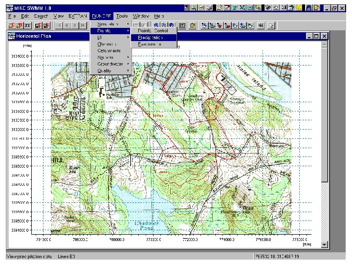
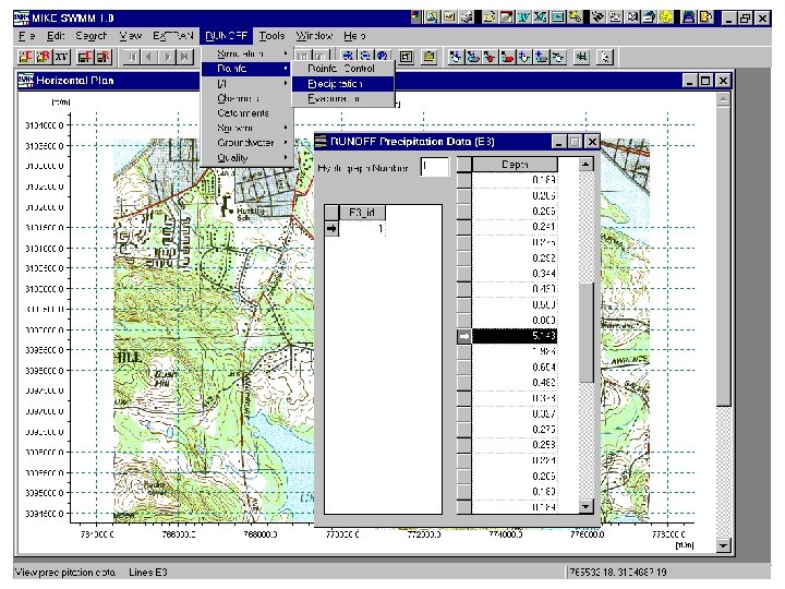
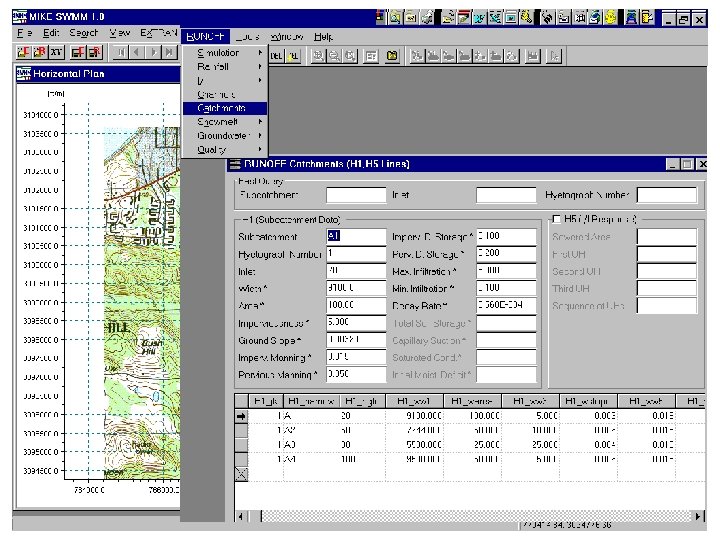
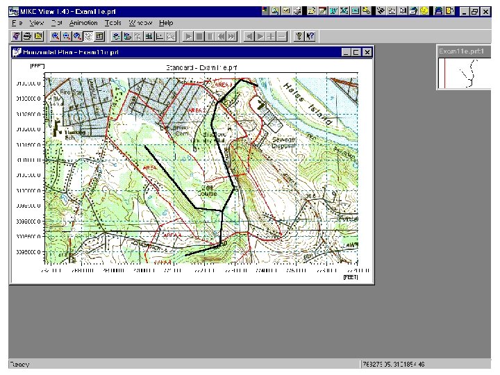
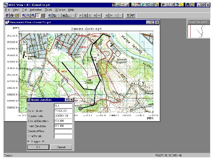
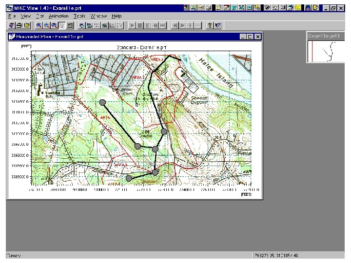
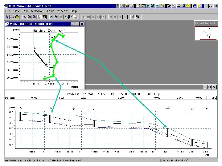
Top of Overbank Top of Bank Culvert
Road Elev. Junction 110 Road Junction 60 Culvert Road Culvert
Road Elev. Junction 110 Road Culvert
Road Elev. Junction 110 Road Culvert
Road Elev. Junction 110 Road Culvert
Road Elev. Junction 110 Junction 60 Culvert Road Culvert

Modeling an Urban Development with MIKE-SWMM Presented by: Melissa Figurski CE 394 K. 2 Surface Water Hydrology Term project, Spring 2001
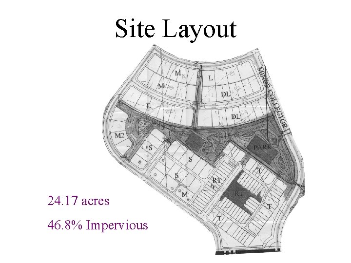
Site Layout 24. 17 acres 46. 8% Impervious
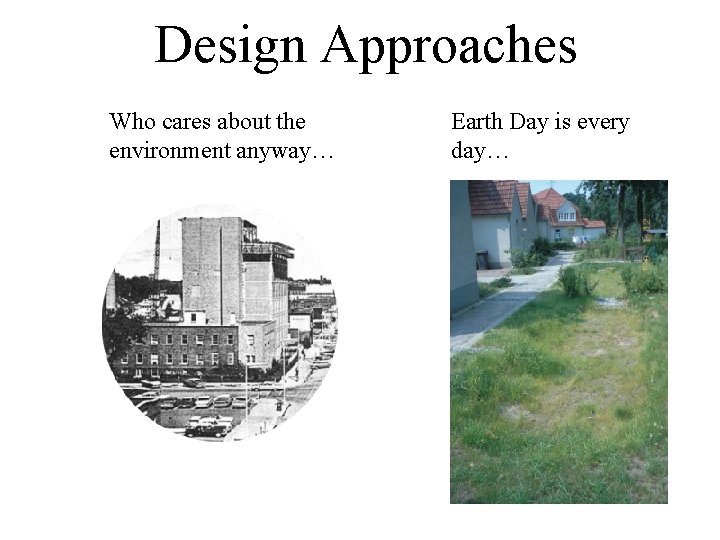
Design Approaches Who cares about the environment anyway… Earth Day is every day…
MIKE-SWMM Evaluations • Pre-development – Natural runoff • Post-development – Sewer system pipe runoff – Grassy swale to detention pond runoff
Design Criteria, City of Austin • Drainage Criteria Manual – detention ponds • “Ponds shall be designed to reduce post-development peak rates of discharge to existing pre-development peak rates of discharge from the 2, 10, and 25 year storm events at each point of discharge from the project or development site. ” • Environmental Criteria Manual – runoff treatment volume • “one-half inch of runoff plus an additional one-tenth inch for each ten percent increase of gross impervious cover twenty percent within the drainage area to the control”
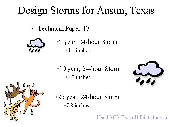
Design Storms for Austin, Texas • Technical Paper 40 • 2 year, 24 -hour Storm • 4. 1 inches • 10 year, 24 -hour Storm • 6. 7 inches • 25 year, 24 -hour Storm • 7. 8 inches Used SCS Type-II Distribution
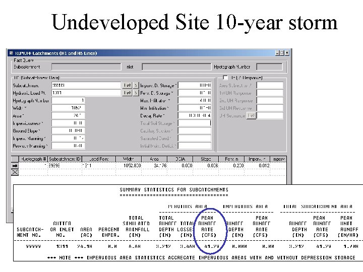
Undeveloped Site 10 -year storm
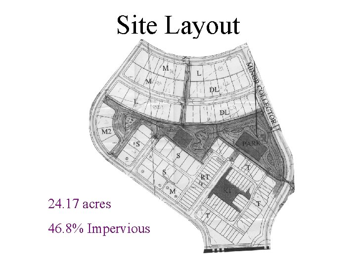
Site Layout 24. 17 acres 46. 8% Impervious
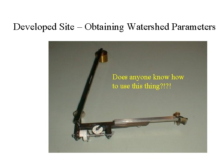
Developed Site – Obtaining Watershed Parameters Does anyone know how to use this thing? !? !
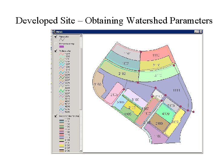
Developed Site – Obtaining Watershed Parameters
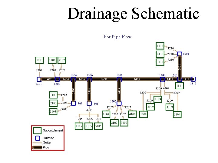
Drainage Schematic For Pipe Flow
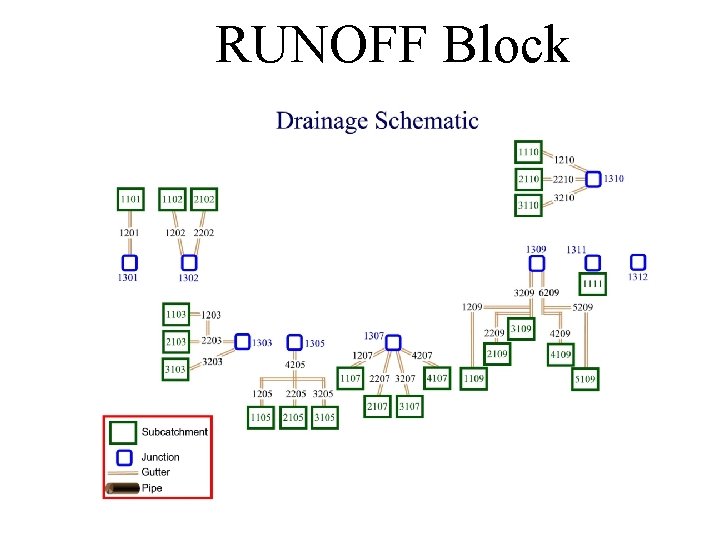
RUNOFF Block
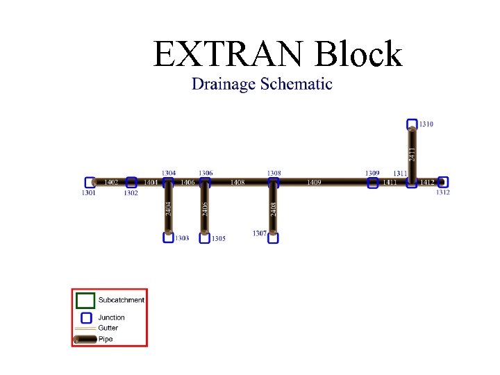
EXTRAN Block
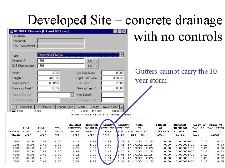
Developed Site – concrete drainage with no controls Gutters cannot carry the 10 year storm
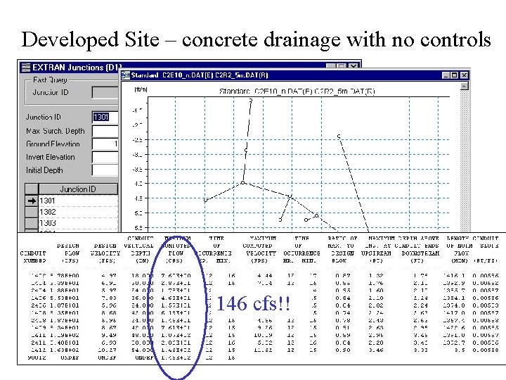
Developed Site – concrete drainage with no controls 146 cfs!!
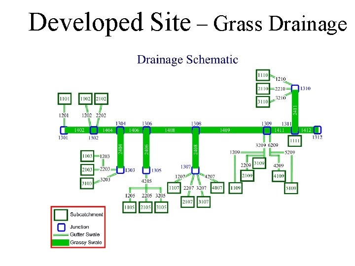
Developed Site – Grass Drainage
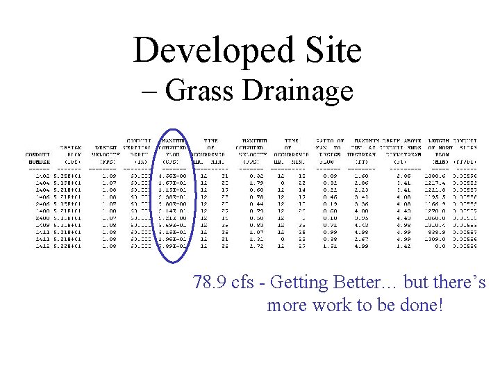
Developed Site – Grass Drainage 78. 9 cfs - Getting Better… but there’s more work to be done!
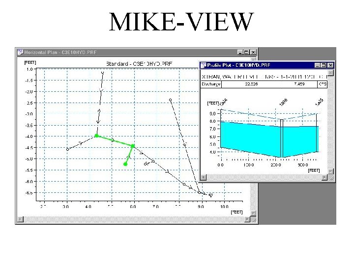
MIKE-VIEW
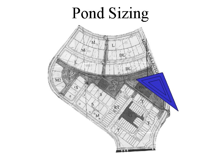
Pond Sizing
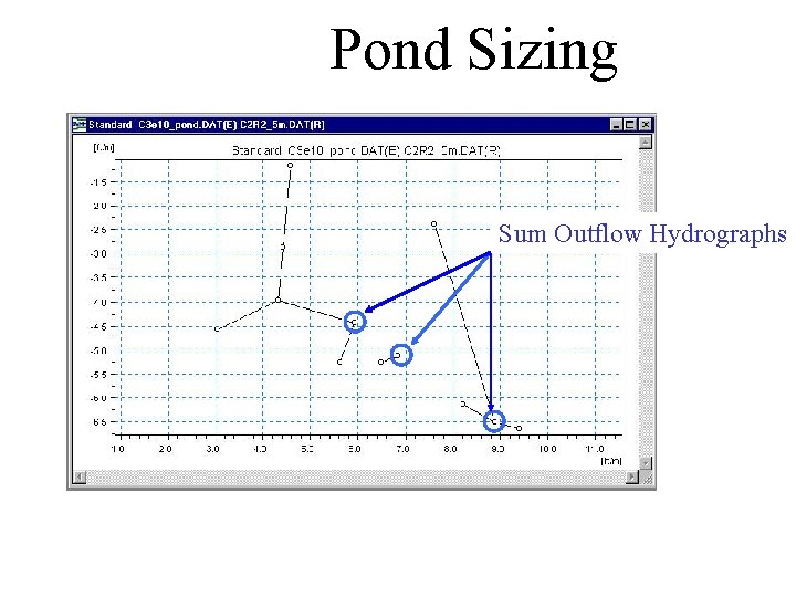
Pond Sizing Sum Outflow Hydrographs
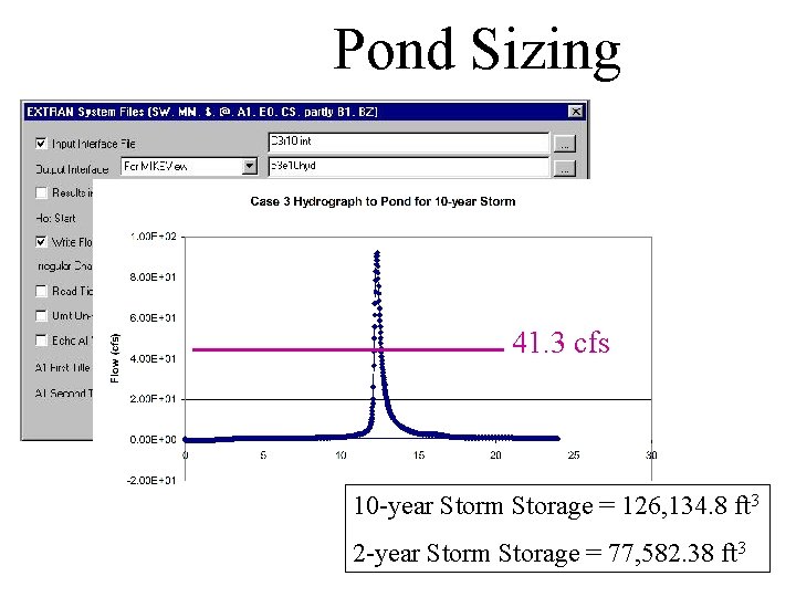
Pond Sizing 41. 3 cfs 10 -year Storm Storage = 126, 134. 8 ft 3 2 -year Storm Storage = 77, 582. 38 ft 3
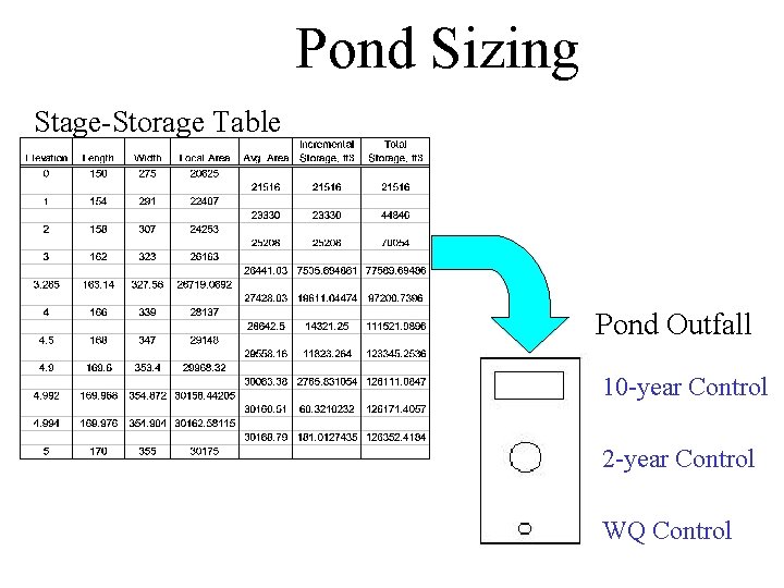
Pond Sizing Stage-Storage Table Pond Outfall 10 -year Control 2 -year Control WQ Control
Almost There… • Input Pond Stage/Storage Data into MIKESWMM • Size Pond Outfall Structures for 2 and 10 year Storms • Convince World to Use Swales
- Slides: 65