Thin Film Magnetism The Reflectometric Approach Dnes Lajos


![Magnetisation and SMR field dependence of a Mg. O(001)[57 Fe(26Å)/Cr(13Å)]20 multilayer ESRF ID 18 Magnetisation and SMR field dependence of a Mg. O(001)[57 Fe(26Å)/Cr(13Å)]20 multilayer ESRF ID 18](https://slidetodoc.com/presentation_image/36dd6e47b2ec2d226e2ed0480532c343/image-38.jpg)
![Magnetisation and SMR field dependence of a Mg. O(001)[57 Fe(26Å)/Cr(13Å)]20 multilayer Magnetisation and SMR field dependence of a Mg. O(001)[57 Fe(26Å)/Cr(13Å)]20 multilayer](https://slidetodoc.com/presentation_image/36dd6e47b2ec2d226e2ed0480532c343/image-39.jpg)

![Bulk spin flop in an epitaxial Mg. O(001)[57 Fe(26Å)/Cr(13Å)]20 multilayer ESRF ID 18 0 Bulk spin flop in an epitaxial Mg. O(001)[57 Fe(26Å)/Cr(13Å)]20 multilayer ESRF ID 18 0](https://slidetodoc.com/presentation_image/36dd6e47b2ec2d226e2ed0480532c343/image-41.jpg)


![Domain ripening: off-specular SMR Mg. O(001)[57 Fe(26Å)/Cr(13Å)]20 2 @ AF reflection Decreasing the field Domain ripening: off-specular SMR Mg. O(001)[57 Fe(26Å)/Cr(13Å)]20 2 @ AF reflection Decreasing the field](https://slidetodoc.com/presentation_image/36dd6e47b2ec2d226e2ed0480532c343/image-54.jpg)

![Spin-flop-induced domain coarsening (SMR) 100 Mg. O(001)[57 Fe(26Å)/Cr(13Å)]20 2 @ AF reflection prompt reflected Spin-flop-induced domain coarsening (SMR) 100 Mg. O(001)[57 Fe(26Å)/Cr(13Å)]20 2 @ AF reflection prompt reflected](https://slidetodoc.com/presentation_image/36dd6e47b2ec2d226e2ed0480532c343/image-56.jpg)
![Spin-flop induced domain coarsening (PNR) Mg. O(001)[57 Fe(26Å)/Cr(13Å)]20 7 m. T 14. 2 m. Spin-flop induced domain coarsening (PNR) Mg. O(001)[57 Fe(26Å)/Cr(13Å)]20 7 m. T 14. 2 m.](https://slidetodoc.com/presentation_image/36dd6e47b2ec2d226e2ed0480532c343/image-57.jpg)


- Slides: 63

Thin Film Magnetism: The Reflectometric Approach Dénes Lajos Nagy KFKI Research Institute for Particle and Nuclear Physics and Eötvös Loránd University , Budapest, Hungary Thin Films as Seen by Local Probes ERASMUS Intensive Programme Frostavallen (Höör), Sweden, 2 -12 May, 2002

Outline · A brief survey of thin film magnetism exchange coupling in multilayers magnetic anisotropy in thin films · Principles of reflectometry · Polarised neutron reflectometry (PNR)

Outline · Synchrotron Mössbauer reflectometry (SMR) depth selectivity electronically allowed and forbidden reflections time integral and time differential SMR · Antiferromagnetically coupled multilayers the spin flop transition domain formation, ripening and coarsening · Summary

Exchange coupling in multilayers · Within a single layer: “rigid” ferromagnetic coupling. · Bilinear layer coupling: with · J 1 > 0: ferromagnetic J 1 < 0: antiferromagnetic coupling ® M(H) is linear up to saturation

Oscillatory exchange coupling in multilayers D. T. Pierce et al. , J. Magn. Mater. 200, 290 (1999).

Exchange coupling in multilayers · Bilinear + biquadratic coupling: ·J 2 < 0: preferred 90° orientation ® M(H) is nonlinear around saturation

Bilinear vs. bilinear + biquadratic coupling

Magnetic anisotropy in thin films · Shape anisotropy is the consequence of the anisotropy of the dipole–dipole interaction. In case of thin films, it leads to a preferred in plane magnetisation. · Magnetocrystalline anisotropy: The crystal electric field splits the orbital levels. Therefore, the spin orbit coupling leads to preferred orientation of the magnetisation (easy axes).

Magnetocrystalline anisotropy in thin films · Volume anisotropy: The anisotropy energy follows the symmetry of the crystal lattice. In case of thin films, this leads to in plane anisotropy. The in plane symmetry may be, e. g. : uniaxial, e. g. Fe(211) – grown on Mg. O(110), fourfold, e. g. Fe(110) – grown on Mg. O(001), etc.

Magnetic anisotropy in thin films · Surface and interface anisotropy: The symmetry of the crystal is broken at the surface and at interfaces leading to an axial component of the crystal electric field with its axis perpendicular to the surface or the interface. Via spin orbit coupling, this leads to a preferred out of plane magnetisation. · Deformation anisotropy: The relaxation of the lattice at the surface or the lattice mismatch at epitaxial interfaces results in this kind of anisotropy via magnetoelastic effects.

Magnetic anisotropy in thin films · The layer thickness and temperature dependence of the exchange coupling and anisotropy leads to a variety of magnetic and domain structures in thin films and multilayers at different layer thickness, temperature and magnetic field. The competition of in plane and out of plane anisotropy may lead to the spin reorientation transition.

source sample detector

source detector sample Reflection geometry: depth selectivity

Neutron, X-ray and Mössbauer reflectometry · Total external reflection appears for . For thermal neutrons and hard x rays: |n 1| 10 5. c 1. . . 10 mrad grazing incidence experiment is possible. · Specular reflected beam: The intensity rapidly decreases for > c with increasing scattering vector Q = 2 k · sin .

Neutron, X-ray and Mössbauer reflectometry · In a stratified medium: reflected and refracted beams appear at each interface interference. · The reflected intensity R(Q) = r(Q) 2 bears information on the depth profile of the index of refraction n(z). In frames of a given model for the stratified system, n(z) can be reconstructed from R(Q), e. g. , with the method of the characteristic matrices.

Neutron, X-ray and Mössbauer reflectometry Relation between scattering amplitude and index of refraction:

Neutron reflectometry: the scattering amplitudes isotope specific scattering length + for neutron spin parallel to magnetisation - for neutron spin antiparallel to magnetisation for neutron spin perpendicular to magnetisation: spin flip scattering!

X-ray and Mössbauer reflectometry: the scattering amplitudes µ electron density hyperfine matrix elements photoabsorption hyperfine energies

Mössbauer reflectometry: the optical model · The optical approach for grazing incidence is valid, however it leads to a characteristic matrix problem in the optics of an anisotropic, opti cally active and absorptive medium. f M’ L’ f: scattering amplitude : susceptibility M’: differential propagation matrix L’: characteristic matrix The reflectivity amplitude is: with

Polarised neutron scattering (H. Zabel)

Polarised neutron scattering (H. Zabel)

Polarised neutron scattering (H. Zabel)

Polarised neutron reflectometry (H. Zabel)

Polarised neutron reflectometry (H. Zabel)

Polarised neutron reflectometry (H. Zabel)

Polarised neutron reflectometry (H. Zabel)

Polarised neutron reflectometry (H. Zabel)

Mössbauer reflectometry: why at synchrotrons? · Due to the small (1 2 cm) size of the sample and the small (1 10 mrad) angle of grazing incidence, the solid angle involved in a Mössbauer reflectometry experiment is 10 5 only 1 photon from 106 is used in a conventional source experiment. In contrast, the highly collimated SR is fully used. · The linear polarisation of the SR allows for an easy determination of the magnetisation direction.

Arrangement of an SMR experiment z from the high resolution monochromator y x APD E 2 or k w Hext /2 scan: qz scan w scan: qx scan

Depth selective phase analysis with SMR · Close to the critical angle of electronic total reflection, the penetration depth of hard x rays strongly depends on the angle of grazing incidence. For iron at E = 14. 4 ke. V: [mrad] 5 4 3 0 d [nm] 40. 5 20. 5 3. 5 1. 3 · By changing around c one can adjust the depth at which the thin film is ‘sampled’. Example: oxidised 57 Fe films (V. G. Semenov et al. )


Depth selective phase analysis with SMR

Electronically allowed and forbidden reflections Float glass/57 Fe(22. 5 Å)/[56 Fe(22. 5 Å)/57 Fe(22. 5 Å)]15/Al(90 Å)

Time-integral and time-differential SMR · Time integral SMR: total number of delayed photons from t 1 to t 2 as a function of (delayed – 2 scan). t 1: deadtime, bunch quality t 2: bunch repetition time · As a rule, a – 2 scan of the prompt photons (i. e. , conventional x ray reflectometry) is recorded along with a time integral SMR scan.

Time-integral and time-differential SMR · Time differential SMR: time response measurement in a fixed – 2 geometry. hyperfine interaction quantum beats · Full SMR: prompt – 2 scan delayed time integral – 2 scan a set of time response reflectivity measurements · All these data should be evaluated simultaneously.

Time-integral and time-differential SMR

Antiferromagnetic reflections in SMR and the direction of the layer magnetisation ( /2 -scan) z y B z By E x k E z y B x k 1 2 3 4 5 6
![Magnetisation and SMR field dependence of a Mg O00157 Fe26ÅCr13Å20 multilayer ESRF ID 18 Magnetisation and SMR field dependence of a Mg. O(001)[57 Fe(26Å)/Cr(13Å)]20 multilayer ESRF ID 18](https://slidetodoc.com/presentation_image/36dd6e47b2ec2d226e2ed0480532c343/image-38.jpg)
Magnetisation and SMR field dependence of a Mg. O(001)[57 Fe(26Å)/Cr(13Å)]20 multilayer ESRF ID 18
![Magnetisation and SMR field dependence of a Mg O00157 Fe26ÅCr13Å20 multilayer Magnetisation and SMR field dependence of a Mg. O(001)[57 Fe(26Å)/Cr(13Å)]20 multilayer](https://slidetodoc.com/presentation_image/36dd6e47b2ec2d226e2ed0480532c343/image-39.jpg)
Magnetisation and SMR field dependence of a Mg. O(001)[57 Fe(26Å)/Cr(13Å)]20 multilayer

The bulk spin flop in AF-coupled multilayers · Fourfold in plane magnetocrystalline anisotropy. · All layer magnetisations are aligned along the same easy axis. · At a moderate increasing magnetic field parallel to the easy axis in which the layer magnetizations lay, all magnetisations jump to the perpendicular easy direction. · The new alignment is retained in remanence.
![Bulk spin flop in an epitaxial Mg O00157 Fe26ÅCr13Å20 multilayer ESRF ID 18 0 Bulk spin flop in an epitaxial Mg. O(001)[57 Fe(26Å)/Cr(13Å)]20 multilayer ESRF ID 18 0](https://slidetodoc.com/presentation_image/36dd6e47b2ec2d226e2ed0480532c343/image-41.jpg)
Bulk spin flop in an epitaxial Mg. O(001)[57 Fe(26Å)/Cr(13Å)]20 multilayer ESRF ID 18 0 1/2 250 200 150 1 100 Counts 3/2 50 20 16 12 0. 0 0. 2 0. 4 0. 6 0. 8 [deg] 1. 0 1. 2 8 4 0 H [m. T] 5 4 1 2 3

1. 0 0. 8 3 0. 6 Kerr angle (mdeg) Normalised AF peak intensity Magnetisation and SMR field dependence of a Mg. O(100)[57 Fe(26Å)/Cr(13Å)]20 multilayer during the bulk spin flop 0. 4 0. 2 2 up 1 down 0 up again -1 -3 0 Hsf -2 -30 -20 -10 0 10 20 30 H (m. T) 0 10 20 H (m. T) 30 40

The “Smirnov figures” for SMR The quantum beat patterns of a thin resonant 57 Fe layer show exactly the same dependence on the direction of the hyperfine field as they do in the forward scattering case.

Perpendicular magnetic anisotropy An out of plane anisotropy of the Fe magnetisation was observed using the 57 Fe marker layer technique in the inner region of 7 mono layers fcc Fe enclosed between ferromagnetic fcc Co layers stabilised by Cu. The outer regions show an FM coupling to Co and an increased hyperfine magnetic field. (C. Carbone et al. , unpublished)

Antiferromagnetic domains in multilayers S. S. P. Parkin et al, 1993. Layer magnetisations:

Domains in a Fe/Cr/Fe trilayer M. Rührig et al. , Phys. Stat. Sol. (a) 125, 635 (1991). M. Rührig, Theses, 1993.

Formation of patch domains. . . … in Greek mythology

Antiferromagnetic multilayer leaving magnetic saturation z H = 0. 95 Hsat y x H || x H > Hsat

Formation of two kinds of domains z y x z y

Domain formation on leaving saturation


From saturation to remanence: the domain ripening 1. The correlation length of the domains immediately after their formation is equal to the lateral structural correlation length of the multilayer (terrace length, £ 50 nm). Still, in remanence we observe mm size domains. Why? 2. The driving force of the spontaneous change of the domain size in decreasing field is the domain wall energy. The sign of the size change depends on the scaling law of the domain wall density: inclusions (µ x) decreasing domain size chessboard (µ 1/x) increasing domain size

Domain ripening: the final state · The correlation length of the primary domains in remanence is determined by the domain wall energy driven and coercivity limited spontaneous growth (ripening). Ripening takes place when the applied magnetic field is decreased from the saturation region to zero. · Critical domain size after ripening: with the domain wall width for 2 Oe < Hc < 30 Oe: 0. 6 mm < xc < 8. 4 mm
![Domain ripening offspecular SMR Mg O00157 Fe26ÅCr13Å20 2 AF reflection Decreasing the field Domain ripening: off-specular SMR Mg. O(001)[57 Fe(26Å)/Cr(13Å)]20 2 @ AF reflection Decreasing the field](https://slidetodoc.com/presentation_image/36dd6e47b2ec2d226e2ed0480532c343/image-54.jpg)
Domain ripening: off-specular SMR Mg. O(001)[57 Fe(26Å)/Cr(13Å)]20 2 @ AF reflection Decreasing the field and having left the saturation region, the AF peak appears with increasing intensity. In Hext = 0. 3 T the domain size is x 500 nm. On decreasing the field to 0, the domain size increases to x = 2. 6 mm. Domain ripening is an irreversible process: the domain size no longer changes in increasing or decreasing field.

Formation of very large domains (coarsening) · After ripening, the domain size in remanence is expected to be always about 500 nm … 5 mm. · This is not the case! The domain size is a complicated function of the magnetic prehistory. Under favourable conditions, even much larger domains (up to mm? ) may be formed.
![Spinflopinduced domain coarsening SMR 100 Mg O00157 Fe26ÅCr13Å20 2 AF reflection prompt reflected Spin-flop-induced domain coarsening (SMR) 100 Mg. O(001)[57 Fe(26Å)/Cr(13Å)]20 2 @ AF reflection prompt reflected](https://slidetodoc.com/presentation_image/36dd6e47b2ec2d226e2ed0480532c343/image-56.jpg)
Spin-flop-induced domain coarsening (SMR) 100 Mg. O(001)[57 Fe(26Å)/Cr(13Å)]20 2 @ AF reflection prompt reflected intensity (% of max. ) 50 100 delayed in remanence after 4. 07 T 50 0 100 ¬ 90° rot. delayed in remanence after 13 m. T 50 0 100 Correlation length: x = 1/Dqx delayed in remanence after 35 m. T 50 0 -6 -4 -2 0 2 -4 -1 q x (10 Å ) 4 6 Delayed photons before the spin flop x = 2. 6 mm Delayed photons after the spin flop x 1 > 16. 5 mm x 2 = 2. 6 mm ESRF ID 18
![Spinflop induced domain coarsening PNR Mg O00157 Fe26ÅCr13Å20 7 m T 14 2 m Spin-flop induced domain coarsening (PNR) Mg. O(001)[57 Fe(26Å)/Cr(13Å)]20 7 m. T 14. 2 m.](https://slidetodoc.com/presentation_image/36dd6e47b2ec2d226e2ed0480532c343/image-57.jpg)
Spin-flop induced domain coarsening (PNR) Mg. O(001)[57 Fe(26Å)/Cr(13Å)]20 7 m. T 14. 2 m. T 35 m. T non spin flip scattering p || M p M JINR Dubna SPN 1

Domain coarsening on spin flop · Coarsening on spin flop is an explosion like 90 deg flop of the magnetization annihilating primary 180 deg walls. It is limited neither by an energy barrier nor by coercivity. Consequently, the correlation length of the secondary patch domains x may become comparable with the sample size.

Domain coarsening during spin flop

Summary · Reflectometry is a powerful tool for studying the depth profile of the scattering length density in thin films. · The scattering length density is sensitive to the electron density (non resonant x rays), kind of the isotopes, as well as the strength and direction of the magnetisation (thermal neutrons), electron density, as well as the strength and orientation of the hyperfine interactions (nuclear resonant / Mössbauer x rays).

Summary · In neutron reflectometry, the antiferromagnetic structure of a coupled magnetic multilayer results in half order Bragg peaks. · In polarised neutron reflectometry (PNR) with spin analysis the field (and neutron spin ) parallel (ferromagnetic) magnetisation of a magnetic multilayer results in non spin flip scattering, the field (and neutron spin ) perpendicular (antiferromagnetic) magnetisation of a magnetic multilayer results in spin flip scattering.

Summary · In (synchrotron) Mössbauer reflectometry (SMR), the antiferromagnetic structure of a coupled magnetic multilayer results in half order Bragg peaks, provided that (for 1/2® 3/2 SMR) the magnetisation is parallel to the photon propagation direction. · Off specular (diffuse) reflectivity is sensitive to the in plane autocorrelation of the scattering length density. Off specular reflectivity measured at a half order reflection maps the antiferromagnetic domain structure of a coupled magnetic multilayer (both for PNR and SMR).

References 1. L. Deák et al. , Phys. Rev. B 53, 6158 (1996). 2. A. I. Chumakov et al. , Hyp. Int. 123/124, 427 (1999). 3. J. F. Anker, G. P. Felcher, J. Magn. Mater. 200, 741 (1999). 4. H. Spiering, L. Deák, L. Bottyán, Hyp. Int. 125, 197 (2000). 5. D. L. Nagy et al. , Hyp. Int. 126, 353 (2000). 6. G. P. Felcher, S. G. E. te Velthuis, Appl. Surf. Sci. 7151, 1 (2001). 7. D. L. Nagy et al. , Phys. Rev. Lett. 88, 157202 (2002). and references in those papers…
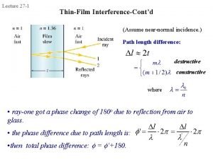
 Thin film interference
 Thin film texture
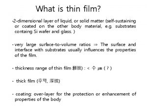
 What is thin film
 Interference in thin film
 Coherent and incoherent sources of light
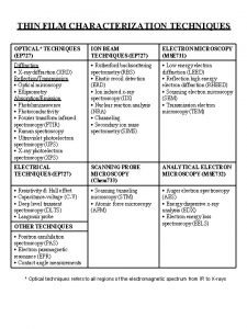
 Thin film characterization techniques
 Film interference
 What is thin film in physics
 Pvc thin film
 Sputtering thin film
 Opaquant meaning
 Interference in thin film
 Monolithic ic
 Thick and thin film preparation
 Csepi lajos
 Mezoszint
 Tarczy lajos alapiskola hetény
 Praxismenedzsment
 Lajos bokros
 Erdős lajos
 Muha lajos
 Dr mester lajos szeged
 Bartha lajos mnb
 Vass lajos általános iskola
 Liturgicky kalendar dnes
 Vzneseny tak jemny akordy
 Tma dnes
 Tübüloveziküler sistem
 Antony dnes
 Lieberkühn bezleri
 Detska praca v minulosti a dnes
 Meníny dnes
 Derinin dnes hücreleri
 Prvn meaning
 Akym pismom piseme
 Volny vers
 Nedea
Nedea Práca v minulosti a dnes
 Becő termésű növények
 Vezmi dnes sviecku do dlani
 Explain wedge film and squeeze film journal bearings
 Cognitive approach vs behavioral approach
 Cognitive approach vs behavioral approach
 Process of research definition
 Waterfall and sprinkler strategy
 Multi approach avoidance conflict
 Approach to system development
 Datagram networks and virtual circuit networks
 Deep learning approach and surface learning approach
 Chapter 36 magnetism answer key
 Electromagnet experiment hypothesis
 F equals qvb
 Electricity and magnetism
 Chapter 24 magnetism magnetic fundamentals answers
 Ultrafast magnetism
 Magnetism
 Magnetism
 Is magnetism an invisible force
 Electromagnetic application
 Electric fuse and circuit breaker graphic organizer
 Physics 102
 Magnetism lesson outline answer key
 Electricity and magnetism vocabulary
 Gauss law in magnetism

