Thermocouples Working Principle Seebeck effect when any conductor

Thermocouples
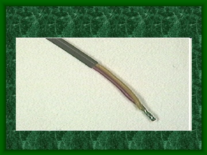

Working Principle • Seebeck effect when any conductor subjected to thermal gradient generates a voltage.


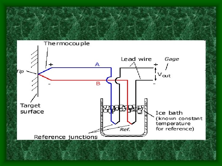
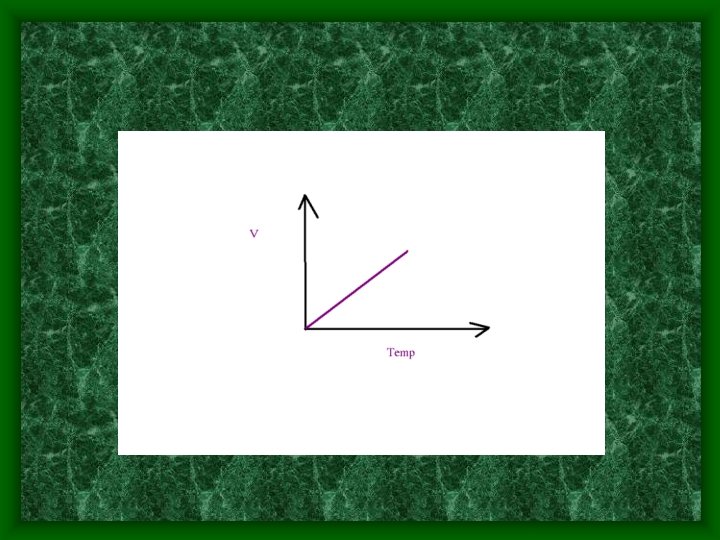
To measure this thermal gradient - connect another conductor. voltage depends on type of metal used. Difference – 1 – 70 micro volts per degree C Thermocouple gives difference in temp. not the absolute value

Current continues to flow as long as T 2>T 1 Emf e= a 1 + a 2 ( ) 2+……. + an ( ) n Finally reduced to e= a 1 Thermocouples behaves according to thermo electric laws

Thermo electric laws 1. The application of heat to a single homogeneous metal in itself is not capable of producing electric current 2. Thermo electric emf is produced when two junctions of 2 dissimilar homogenous metal kept at different temp ( emf not affected by temp. gradient)

3. Emf produced by 2 dissimilar metals having jns. at diff. Temp. , emf developed will not be affected when a third metal is made a part of ckt. – based on law of intermediate metals 4. Law of intermediate temp. Eac= Eab + Ebc

Law of intermediate metals : states that net emf in a circuit remains unaltered if a third metal is introduced provided that the two junctions of third metals are at same temp

Helps it possible to use extension wires Eg. For platinum –rhodium thermocouple we can use Cu as extension wire- made less expensive

Features • • • O/p in mv Need ampr Compesion ckts. Less accurate Kept inside protective wells Cheaper when compared to RTD

IC temp transducers Ics used as temp. transducer Most linear Highest o/p Prone to self heating

Ics used LM 335 series LM 35 series AD 592 series

Lm 335 series • Uses a temp sensitive zener diode • Provides o/p- 10 mv /K

Lm 34 series Precision sensor O/p V proportional to F O/p 10 mv /F Low cost, Low o/p impedance, Linear Draws little I (about 70 micro amps) To measure zero degree needs –ve supply

AD 592 series Used when data has to be transmitted over a distance

Torque measurement

Torque measurement body depends on angular displacement or tension To measure –torque- a shaft of calibrated length- attached to shaft Strain produced- sensed by transducerconverted to torque by calibration

Strain gauge torque transducer
 / 2")
Strain gauge transducer T = G ( R 4 – r 4) / 2 L G- Rigidity Modulus R- outer radius of shaft R- inner radius of shaft L- length of shaft - angular deflection
![45 = +/- [ TR / [ G (R 4 - r 4)]](http://slidetodoc.com/presentation_image_h2/266fae1dad35824c182cbfb73bf75990/image-23.jpg "45 = +/- [ TR / [ G (R 4 - r 4)]")
45 = +/- [ TR / [ G (R 4 - r 4)] ie, strain Torque Strain gauge connected to bridge ckt with power source & display system

Strain gauge transducer • • • usually 4 gauges in the form of bridge 1&2 diametrically opposite to each other 3& 4 diametrically opposite provides temp. compensation. Better stability

Inductive type transducer

Inductive type • Flange A – Coil • Flange B – Core moves in& out according to displacement of flange So L varied, coil connected to Ac bridge, o/p proportional to torque

Digital method

Digital Method Flange has a tooth. When non torque- teeth aligned perfectly. Teeth produced V in coils. Two pulses compared, At no torque –V pulses occur in both coils simultaneously.

Digtal method When torque applied – phase shift in pulses. Compared. Phase shift calibrated to torque

Magneto-strictive transducer

Magneto- strictive transducer two ac coils wound on a core Kept close to shaft ( flux linkage) So flux path coincides with direction of strain – when torque applies Coil s connected to bridge – initially balanced. L varies with permeability. Torque calibrated

THANK U
- Slides: 32