
Thermions Work Overview at EPDT Karolina Klimek Adam

- Slides: 24
Thermions Work Overview at EP-DT, Karolina Klimek Adam Wątroba Kamil Iwanowski HSSIP November 2018
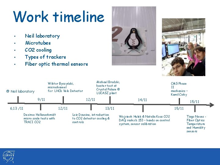
Work timeline • • • Neil laboratory Microtubes CO 2 cooling Types of trackers Fiber optic thermal sensors Michael Brodski, heater test at Crystal Palace @ LUCASZ plant Wiktor Byczyński, microchannel for LHCb Velo Detector @ Neil laboratory 9/11 6, 13 /11 12/11 Desiree Hellenschmidt micro scale tests with TRACI CO 2 CMS Phase II mechanics – Kamil Cichy 14/11 13/11 Loic Davoine, introduction to CO 2 detector cooling & controls 15/11 Wojciech Hulek & Natalia Koss CO 2 DAQ racks b. 153 – hands on control system, sensor calibration Tiago Neves Fiber Optics Temperature and Humidity sensors
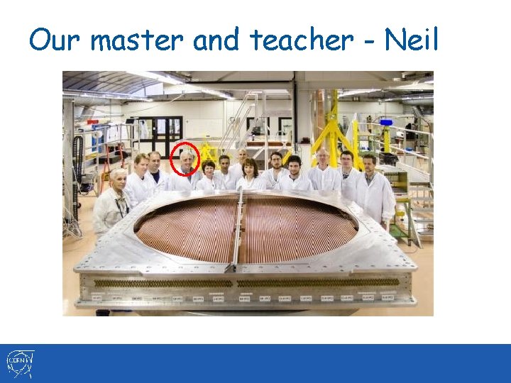
Our master and teacher - Neil
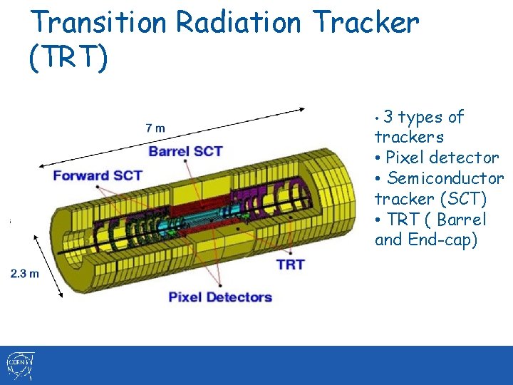
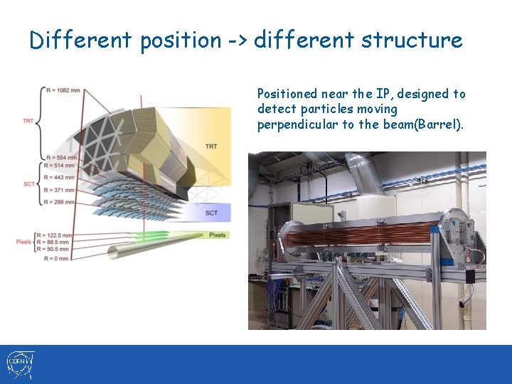
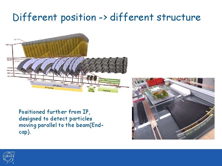
Transition Radiation Tracker (TRT) • 3 types of trackers • Pixel detector • Semiconductor tracker (SCT) • TRT ( Barrel and End-cap)
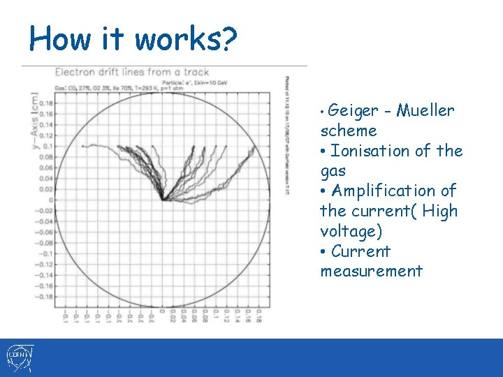
How it works? • Geiger - Mueller scheme • Ionisation of the gas • Amplification of the current( High voltage) • Current measurement
Different position -> different structure Positioned near the IP, designed to detect particles moving perpendicular to the beam(Barrel).
Different position -> different structure Positioned further from IP, designed to detect particles moving parallel to the beam(Endcap).
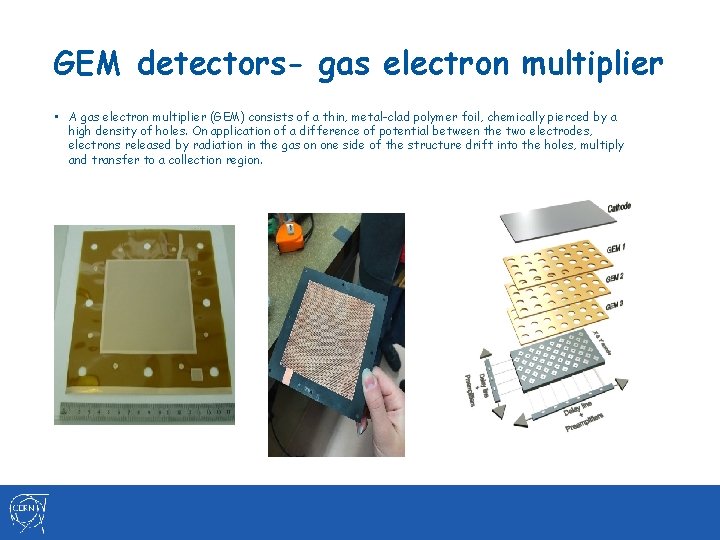
GEM detectors- gas electron multiplier • A gas electron multiplier (GEM) consists of a thin, metal-clad polymer foil, chemically pierced by a high density of holes. On application of a difference of potential between the two electrodes, electrons released by radiation in the gas on one side of the structure drift into the holes, multiply and transfer to a collection region.
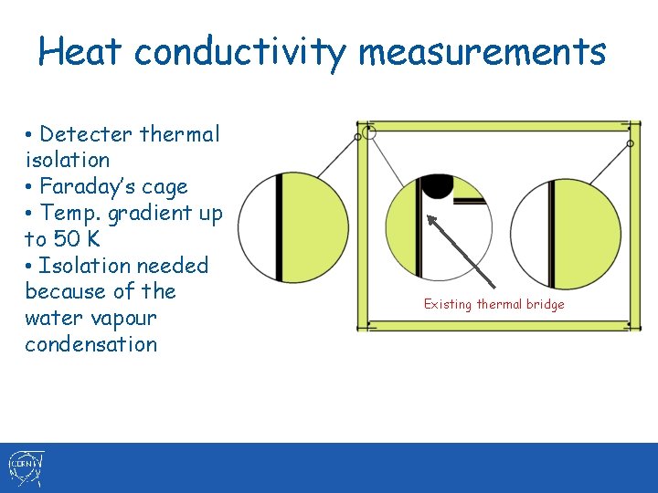
Heat conductivity measurements • Detecter thermal isolation • Faraday’s cage • Temp. gradient up to 50 K • Isolation needed because of the water vapour condensation Existing thermal bridge
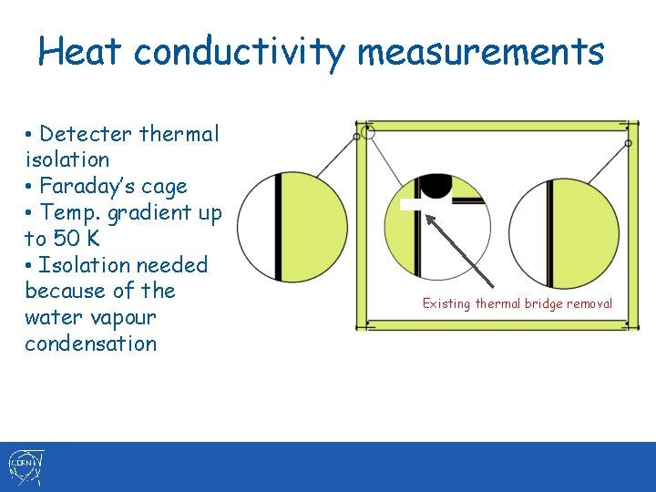
Heat conductivity measurements • Detecter thermal isolation • Faraday’s cage • Temp. gradient up to 50 K • Isolation needed because of the water vapour condensation Existing thermal bridge removal
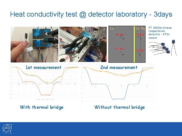
Heat conductivity test @ detector laboratory - 3 days PT 100 1 st measurement With thermal bridge PT 100 2 nd measurement Without thermal bridge PT 100(resistance temperature detector - RTD) sensor
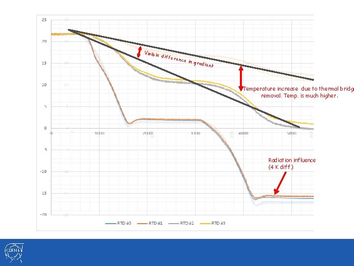
Visible differ ence i n grad ient Temperature increase due to thermal bridge removal. Temp. is much higher. Radiation influence (4 K diff. )
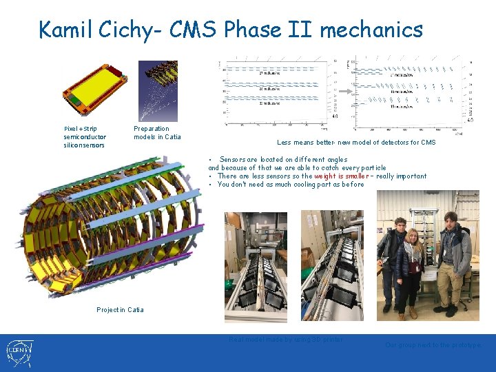
Kamil Cichy- CMS Phase II mechanics Pixel + Strip semiconductor silicon sensors Preparation models in Catia Less means better- new model of detectors for CMS • Sensors are located on different angles and because of that we are able to catch every particle • There are less sensors so the weight is smaller – really important • You don’t need as much cooling part as before Project in Catia Real model made by using 3 D printer Our group next to the prototype.
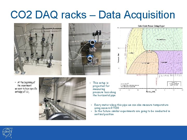
CO 2 DAQ racks – Data Acquisition • This setup is projected for measuring pressure loss along the horizontal pipe • Every meter along this pipe we can also measure temperature using sensors RT 100 • In the future similar experiments are going to be conducted in vertical position
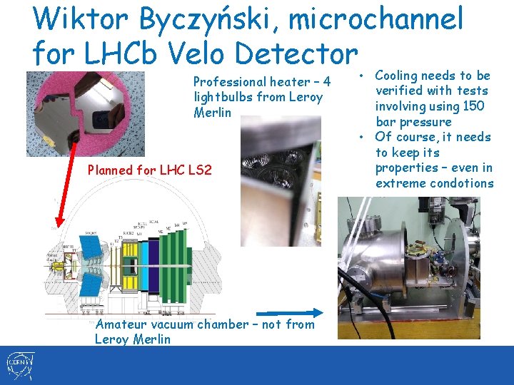
Wiktor Byczyński, microchannel integrated for LHCb Velo Detector • Cooling with silicon wafle • By using CO 2 evaporation to cool circuits, this method is very efficient and eco – friendly • New parts will be installed during LHC LS 2
Wiktor Byczyński, microchannel for LHCb Velo Detector Professional heater – 4 lightbulbs from Leroy Merlin Planned for LHC LS 2 Amateur vacuum chamber – not from Leroy Merlin • Cooling needs to be verified with tests involving using 150 bar pressure • Of course, it needs to keep its properties – even in extreme condotions
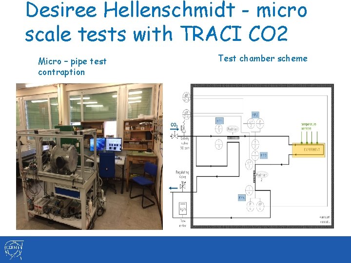
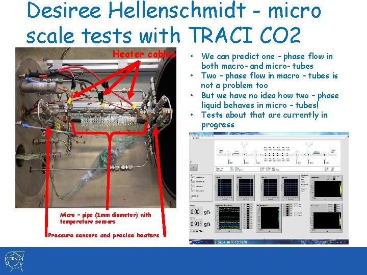
Desiree Hellenschmidt - micro scale tests with TRACI CO 2 Micro – pipe test contraption Test chamber scheme
Desiree Hellenschmidt - micro scale tests with TRACI CO 2 Heater cables • • Micro – pipe (1 mm diameter) with temperature sensors Pressure sensors and precise heaters We can predict one – phase flow in both macro- and micro- tubes Two – phase flow in macro – tubes is not a problem too But we have no idea how two – phase liquid behaves in micro – tubes! Tests about that are currently in progress
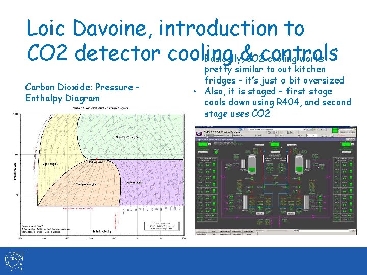
Loic Davoine, introduction to CO 2 detector cooling controls • Basically, & CO 2 cooling works Carbon Dioxide: Pressure – Enthalpy Diagram pretty similar to out kitchen fridges – it’s just a bit oversized • Also, it is staged – first stage cools down using R 404, and second stage uses CO 2
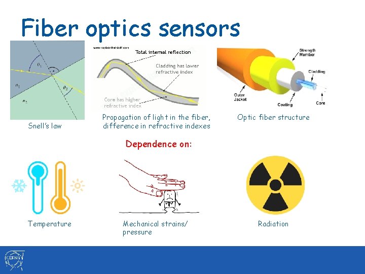
Fiber optics sensors Snell’s law Propagation of light in the fiber, difference in refractive indexes Optic fiber structure Dependence on: Temperature Mechanical strains/ pressure Radiation
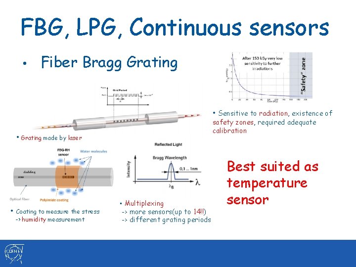
FBG, LPG, Continuous sensors • Fiber Bragg Grating • Sensitive to radiation, existence of safety zones, required adequate calibration • Grating made by laser • Coating to measure the stress -> humidity measurement • Multiplexing -> more sensors(up to 14!!) -> different grating periods Best suited as temperature sensor
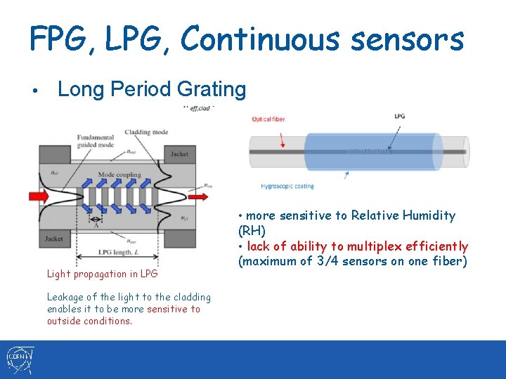
FPG, LPG, Continuous sensors • Long Period Grating Light propagation in LPG Leakage of the light to the cladding enables it to be more sensitive to outside conditions. • more sensitive to Relative Humidity (RH) • lack of ability to multiplex efficiently (maximum of 3/4 sensors on one fiber)
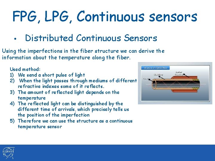
FPG, LPG, Continuous sensors • Distributed Continuous Sensors Using the imperfections in the fiber structure we can derive the information about the temperature along the fiber. Used method: 1) We send a short pulse of light 2) When the light passes through mediums of different refractive indexes some of it reflects. 3) The amount of reflected light depends on the temperature 4) The reflected light can be distinguished by the different time of arrivals, which precisely tells us the position of the imperfection 5) Therefore we can use the structure as a continuous temperature sensor
Thanks for your attention