THEMIS FM 1 INSTRUMENT SUITE PRESHIP REVIEW PSR


- Slides: 35

THEMIS FM 1 INSTRUMENT SUITE PRE-SHIP REVIEW (PSR) ELECTRIC FIELD INSTRUMENT John Bonnell EFI, IDPU and II&T Teams University of California - Berkeley FM 1 Instrument Suite Pre-Ship Review (PSR) EFI-1 UCB September 21, 2005

THEMIS Electric Field Instrument (EFI) FM 1 PSR The THEMIS EFI, IDPU and II&T Teams FM 1 Instrument Suite Pre-Ship Review (PSR) EFI-2 UCB September 21, 2005

Outline • Summary of EFI Status at FM 1 PSR • FM 1 Configuration by SN • End-Item Data Package, Summary and To. C • Final Test and Cal Results vs. Requirement Fulfillment • PFRs • PER EFI RFAs • FM 1 Open Items • Bonus Content: • FM 1 Verification Matrix • FM 1 Vibration Testing Summary • FM 1 TVAC Testing Summary • Response to PER RFA 07 FM 1 Instrument Suite Pre-Ship Review (PSR) EFI-3 UCB September 21, 2005

EFI Status at FM 1 PSR • Requirements and Design: – – • Procurement: – • No major changes to Requirements or Design since M-CDR (see Changes Since M-CDR and PFR Status for details). All RFAs from previous reviews closed out (see following RFA response section). All procurement is complete. Personnel, Assembly and Test: – Team has done an amazing job. – – 5 full FLT complements of SPBs and AXBs have completed functional and environmental testing, and either delivered to II&T or have completed II&T by the end of Aug ’ 05 (roughly 8 weeks per set). BEB assembly complete in Dec ’ 04; bench testing through FM 6 complete. DFB assembly complete in Feb ’ 05; bench testing through FM 5 complete. Reduction in Force complete, Jun ‘ 05. – Final EFI team includes one half-time Scientist (Instrument Lead), one half-time Mech. E (shared with Probe I&T) and one half-time Elect. E (shared with Probe I&T). FM 1 Instrument Suite Pre-Ship Review (PSR) EFI-4 UCB September 21, 2005

FM 1 Configuration • SPBs: – – • AXB 1 (channel 5), +Z: AXB 2 (channel 6), -Z: AXB-FLT-001. AXB-FLT-002. IDPU: – – • SPB-904. SPB-903. SPB-902. SPB-901. AXBs: – – • SPB 1, +X: SPB 2, -X: SPB 3, +Y: SPB 4, -Y: BEB: BEB-004, Flight ACTEL Rev v 8. DFB: DFB-002, Flight ACTEL Rev v 7, v 4. Harness: – – IDPU-to-Booms: Flight Enable Plugs: – – SPB: AXB: FM 1 Instrument Suite Pre-Ship Review (PSR) S/N-001. will be serialized. EFI-5 UCB September 21, 2005

FM 1 End-Item Data Package (EIDP) Delivered Instruments: ~ 13. 1 kg. End-Item Data Package: ~ 22. 5 kg (72% margin!). FM 1 Instrument Suite Pre-Ship Review (PSR) EFI-6 UCB September 21, 2005

FM 1 EIDP: Electrical • THEMIS EFI Preamp: F 1 PWB: • Assembly Records. • Special TVAC Acceptance Test Data. • THEMIS EFI F 1 Sci. Cal: • Sci. Cal Summary (calibration data summary). • DC Response Data (BIAS, SENSOR, FLGND, USHER, GUARD, BRAID). • AC Response Data (SENSOR, FLGND, USHER, GUARD, BRAID). • THEMIS BEB, S/N 004, FM 1 (BINDER 1): • SCHEMATIC, ASSEMBLY AND RE-WORK RECORDS, BOARD-LEVEL TESTING RESULTS, MATE/DEMATE AND POWER LOGS. • THEMIS DFB, S/N 02, FM 1 (BINDER 5): • SCHEMATIC, ASSEMBLY AND RE-WORK RECORDS, BOARD-LEVEL TESTING RESULTS, MATE/DEMATE AND POWER LOGS. • THEMIS Harness: EFI (F 1 -6; no Binder number assigned): • Schematic, assembly and re-work records. • THEMIS Harness: Enable Plugs, Coax Cables (F 1 -6; Binder 24): • Schematic, assembly and re-work records. FM 1 Instrument Suite Pre-Ship Review (PSR) EFI-7 UCB September 21, 2005

FM 1 EIDP: Misc. • THEMIS EFI Preamp PWB and Cable Loading Log (SPB and AXB): • CROSS-REFERENCED LIST BETWEEN BOOM UNIT, CABLE, AND PREAMP S/N. • THEMIS EFI: PA & Cable Drawings (Binder 35): • Mechanical Drawings of Preamp Enclosure and Cable Assembly fixtures. • Assembly and Re-Work records included in individual boom unit assembly records. • THEMIS EFI Deploy Data (F 1 -6): • Sphere/Fine Wire deploy data. • Duplicates of SPB Hi-Bay and TVAC Deploy Test Reports. • Duplicates of AXB Vertical and TVAC Deploy Test Reports. FM 1 Instrument Suite Pre-Ship Review (PSR) EFI-8 UCB September 21, 2005

FM 1 EIDP: SPBs • THEMIS SPB: Vibration Acceptance Testing (FM 1 -2; Binder 12): • Acceptance Vibration Test Reports. • THEMIS SPB Flight Documents: Hi-Bay Full Deployment Testing (F 1 -5; Binder 13): • Deploy Testing Reports (current consumption, length measurement and calibration, deploy rate). • THEMIS EFI: SPB Procs & Schematics (all; Binder 14): • Vacuum Motor Burn-In Test Report. • THEMIS EFI: SPB Mass Properties (F 1 -6; Binder 15): • SPB Mass Properties and ICD Conformance Reports. • THEMIS: SPB Master Mechanical Drawings, FM 1 (Binder 27): • As-Built Mechanical Drawings. • SPB S 90 x: THEMIS (Assembly and Test Records; Binders 8, 9, 10, and 11): • Assembly and rework records for boom unit, preamp enclosure, and cable. • Electrical and mecahnical functional test records. • TVAC test records. FM 1 Instrument Suite Pre-Ship Review (PSR) EFI-9 UCB September 21, 2005

FM 1 EIDP: AXBs • THEMIS Axial Boom: Assembly Records, Flight 1 Upper and Lower Booms, THM-AXB-FLT-001, 002 (Binders 29 and 28): • Boom Wiring Diagram, Assembly and Re-Work Records. • THEMIS Axial Boom: Test Records, Flight 1 Upper and Lower Booms, THM-AXB-FLT-001, -002 (Binders 31 and 30): • Mechanical and Electrical Functional Test records. • Vibration Test Results. • TVAC test Results. • ICD Conformance and Mass Properties. • THEMIS Axial Boom: Vibration test Data, All Flight Units (no Binder number assigned): • Acceptance Vibration Test Data. FM 1 Instrument Suite Pre-Ship Review (PSR) EFI-10 UCB September 21, 2005

RFA Responses, FM 1 -I-PER • SPB Enable Plug Risks (All): – – • Response tendered describing failure mode and risk analysis behind decision not to perform Probe-level deploy testing of SPB systems. Response accepted, and RFA closed. Post-Failure Inspection and Replacement of AXB Sensor Door Axles and Associated Parts (FM 3): – – – Response tendered describing failure mode and risk analysis behind decision to only visually inspect potentially affected parts in all AXB units, and replace visibly damaged parts in the affected unit (FM 3 only). Response accepted, but with qualification by tender, RFA remains open pending further discussion between tender and Cog. E. See Bonus Materials for update of RFA response. FM 1 Instrument Suite Pre-Ship Review (PSR) EFI-11 UCB September 21, 2005

EFI Mission Requirements Fulfillment: • FM 1 MR fulfillment noted in THEMIS Verification Matrix (see MSE Presentation and EFI Bonus Materials). • Integrated EFI and component parts compliant with mission requirements with following exceptions: • Noise level in 0 -4 -k. Hz band somewhat higher than MRD (few times 10 -4 (m. V m-1 Hz-1/2) rather than below that level) -> no significant impact, and requirement waived. FM 1 Instrument Suite Pre-Ship Review (PSR) EFI-12 UCB September 21, 2005

System Noise Level EFI Spectral Coverage and System Noise Estimates Maximum Spectra (DC-Coupled) 1/f 3 1/f flat CDI Measured EFI Noise Level BBF AKR band 1 -LSB Spectra (DC-Coupled) Preamp and Rbias Current Noise Preamp Voltage Noise Spin frequency FM 1 Instrument Suite Pre-Ship Review (PSR) axial radial 10 -Hz Ac-coupled roll-in EFI-13 4 -k. Hz Anti-aliasing roll-off UCB September 21, 2005

Results of Flight Build Testing • • DC and AC Transfer functions agree within Flight sets to better than 1 % on non-critical functions (USHER, GUARD, AC SENSOR gain, etc. ), and better than 0. 2 % on critical, matched functions (BIAS, DC SENSOR gain). Full 16 -bit control of all bias functions demonstrated (control to better than 1 part in 1000, as per MRD). V- and E-channel gains on DFB as per specification. DFB Spectral (Filter Bank, FFT, and AKR) and Derived Quantities data products as per specification. FM 1 Instrument Suite Pre-Ship Review (PSR) EFI-14 UCB September 21, 2005

EFI PFR Status FM 1 Instrument Suite Pre-Ship Review (PSR) EFI-15 UCB September 21, 2005

PFR Status (1) • NNN closed PFRs new since FM 1 PER: PFR-061, -062, -065, -072, -085. • One open PFR relevant to FM 1 PSR: PFR-096. FM 1 Instrument Suite Pre-Ship Review (PSR) EFI-16 UCB September 21, 2005

PFR Status (2) • PFR-061 (EFI Y Floating Monitor Temperature Dependence): • • The response of the EFI Y-axis floating supply current monitor was found to vary more with temperature than the X- and Z-axis floating supply current monitors, and it was also noisier than the other two axes. The problem was traced to a cracked transformer core on the FM 1 LVPS. The damaged inductor was replaced, and the problem did not re-occur. PFR-062 (EFI V 1 Failing Functional Tests in Suite TVAC): • • • The FM 1 V 1 channel of EFI began failing its DC and AC functional tests during Suite TVAC testing. The unit in question was subjected to a boom unit CPT, and visual inspection, at which it was discovered that a high-impedance short existed between the sensor element and the SPB doors, via stray metalization on the plastic insulation on the doors. The excess metalization was removed, the unit restowed, and the problem was fixed. FM 1 Instrument Suite Pre-Ship Review (PSR) EFI-17 UCB September 21, 2005

PFR Status (3) • PFR-072 (Failed Actuation of FM 2 SPB Doors): • • • Design issue with paired series connection of SPB door circuits and SMA end-of-travel switch on SPB Door Actuation circuit. Issue recognized on FM 2, and confirmed on FM 3. Actuation of one SPB of the pair would open the actuator circuit and prevent the other of the pair from opening. Design modified to add shorting plug across end-of-travel switch to SPB Test/Enable Connector; Flight Enable plugs modified as well. Design change keeps safety of end-of-travel switch throughout boom -level functional testing, while keeping one boom from locking out the other in Flight configuration. Rework on all SPB Flight units complete, July 2005. Retesting of deploy circuit completed on FM 1, FM 2, FM 3, August 2005. FM 1 Instrument Suite Pre-Ship Review (PSR) EFI-18 UCB September 21, 2005

PFR Status (3) • PFR-085 (AKR Band Noise Floor is Too High): • • • Problem discovered in FM 2 Omnibus DFB Testing, confirmed in FM 3 and FM 1 tests (generic problem). Diagnosis on FM 1, FM 2, and FM 3 shows problem is conducted noise from +/ -10 V floating power supplies at 150 k. Hz. Noise floor was roughly 30 times over specification (around 100 m. V, as compared to 4. 5 m. V pk amplitude for typical AKR signal). X-axis floating power supply frequency changed to 1. 2 MHz on LVPS (moved frequency out of AKR response band), and tuned LC bypass filter added between V 1 and V 2 inputs to AKR Band (HF Filter) circuit on DFB. New noise level is less than 0. 1 m. V pk, resulting in an expected signal-tonoise ratio of around 40 (very good). PFR-096 (EFI Y IMON Unstable): • • The current monitor on the EFI Y-axis floating supply was found to drift more with time than the X- or Z-axis current monitors. The drift was discovered during the FM 1 CPT, after FM 1 IDPU TVAC Re. Test and workmanship vibe. Diagnosis is on-going. Corrective Measures: – – Spare pair of EFI Preamp PWBs can be swapped in. See also open items LVPS EFI Y-Floater diagnosis and repair. FM 1 Instrument Suite Pre-Ship Review (PSR) EFI-19 UCB September 21, 2005

Open Items FM 1 Instrument Suite Pre-Ship Review (PSR) EFI-20 UCB September 21, 2005

Open Items • Instability of EFI Y IMON (PFR-096): • Risk associated with rework of FM 1 LVPS (Y-FLOATER) is minimal: – • Determine transformer mechanical damage mechanism and mitigate. Risk associated with swapping out EFI Preamps in FM 1 Y-axis (SPB 902, -901) is minimal: – – – Partial SPB cable deploy (part of design). Open preamp enclosure (designed for this possibility). Replace with F 6 spare PWBs. Close preamp enclosure. Restow cable Workmanship Vibe. FM 1 Instrument Suite Pre-Ship Review (PSR) EFI-21 UCB September 21, 2005

Bonus Materials: • • FM 1 Verification Matrix FM 1 Vibration Testing Summary FM 1 TVAC Testing Summary FM 1 IPER RFA-007 Response FM 1 Instrument Suite Pre-Ship Review (PSR) EFI-22 UCB September 21, 2005

EFI Verification Matrix FM 1 Instrument Suite Pre-Ship Review (PSR) EFI-23 UCB September 21, 2005

SPB Acceptance Vibration Protocol Per UCB THEMIS Document THM-SPB-PRO-423 • • • All 3 Axes Sine Survey, . 25 G, 5 – 2000 Hz Sine Strength per Swales TM 2430 -Rev. D, 29 November 2004 Random – Per Swales Document TM 2430 -Rev. D – 7. 09 G RMS – 1 min duration All Vibration Testing Performed at Same Facility, Quanta Labs Retesting (if required) • • ‘Workmanship Shake’ – Validate any design changes following original Flight build shake – Validate rework of any failures on previous vibration test Entire vibration protocol, single axis only Acceptance Sine Strength Specification FM 1 Instrument Suite Pre-Ship Review (PSR) 4 X SPB Flight Units on Vibration Plate EFI-24 Acceptance Random Specification UCB September 21, 2005

SPB Acceptance Vibration Tests Run SPB Serial # Following First Build Retest #1 (Rework/Redesign) Retest #2 (Rework/Redesign) 901, 903 06 Dec 04 31 Jan 05 (Ferrule Redesign) 21 March 05 (Post-Release Springs Redesign) 902, 904 06 Dec 04 14 Dec 04 (Validate Retorquing of bolts that had backed out on first test) 31 Jan 05 (Post Ferrule Redesign) 21 March 05 (Post-Release Springs Redesign) 905, 906, 907, 908 01 Feb 04 04 March 04 (Post-Release Springs Redesign) - - 909, 910, 911 17 Mar 2005 - - - 21 March 05 (Validate failed wire in spool connector from previous test) - - 912 913, 914, 915, 916 17 Mar 2005 25 Apr 2005 FM 1 Instrument Suite Pre-Ship Review (PSR) Retest #3 (Rework/Redesign) - EFI-25 UCB September 21, 2005

SPB Vibration Testing Overview • Deviations from Test Specification (Notching/Force Limiting/Aborts) - • • SPB First Natural Frequency: 144 Hz (Requirement: >75 Hz) Good Sine Sweep Consistency from Unit to Unit (within 15 Hz) Retesting due to Hardware Failure 1. Backing out of bolts (2 X Bolts not torqued correctly at Flight Build) 2. • Resolution: Bolts torqued and spot-bonded, single axis re-vibe completed Single Strand of Cable pulled out of connector at Spool (Assy error) • Resolution: Wire repaired, single axis re-vibe completed Retesting due to Hardware Redesign (FM 1 Only) 1. 2. • None Release Ring Spring Redesigned to Ensure Constant Force on Doors • Resolution: All springs Replaced in all units • Single Axis Retest Completed Preamp Ferrule Crimp Redesigned (Contact discovered to be inconsistent during testing) • Resolution: Ferrule material changed and recrimped • Single Axis Retest Completed Status • Flight Units F 1 -F 5 Vibration Acceptance Testing Completed FM 1 Instrument Suite Pre-Ship Review (PSR) EFI-26 UCB September 21, 2005

AXB Acceptance Vibration Protocol Per UCB THEMIS Document THM-AXB-PRC-302 • • • All 3 Axes Sine Survey, . 25 G, 5 – 2000 Hz, 2 octaves/minute Sine Strength per Swales TM 2430 -Rev. D, 29 November 2004 Random per Swales Document TM 2430 -Rev. D – Qualification: 13. 01 G RMS, 2 min duration – Acceptance: 9. 21 G RMS, 1 min duration All Vibration Testing Performed at Same Facility, Quanta Labs Retesting (if required) • • ‘Workmanship Shake’ – Validate any design/procedure changes following original Flight build shake – Validate rework of any failures on previous vibration test Entire vibration protocol, single axis only FM 1 Instrument Suite Pre-Ship Review (PSR) EFI-27 UCB September 21, 2005

AXB Acceptance Vibration Tests Run AXB Serial # Following First Build Retest #1 (Rework/Redesign) 001, 002 (Flight 1) 11 JAN 05 03 FEB 05 (Proper Accelerometer Location Retest) 003, 004 (Flight 2) 07 FEB 05 - 005, 006 (Flight 3) 25 FEB 05 15 MAR 05 (Sensor Door Mount/Axle Replacement) 007, 008 (Flight 4) 11 APR 05 - 009, 010 (Flight 5) 22 APR 05 - 011, 012 (Flight 6) SCHD. MAY 05 - AXB X Axis Note: Jan 11 2005 testing was to qualification levels due to design modifications relative to the engineering test unit. FM 1 Instrument Suite Pre-Ship Review (PSR) EFI-28 AXB Y Axis AXB Z Axis UCB September 21, 2005

AXB Vibration Testing Overview • Deviations from Test Specification (Notching/Force Limiting/Aborts) - • • AXB Z First Natural Frequency: 300 Hz (Requirement: >75 Hz) Good Sine Sweep Consistency from Unit to Unit (within 15 Hz) AXB X & Y frequencies modeled fixture resonances, suggesting first natural frequency higher than 1800 Hz Retesting due to Improper Test Procedure 1. • Accelerometer was not located at the boom’s center of mass during vibration • Resolution: Accelerometer placed at center of mass and single axis test completed Retesting due to Hardware Failure 1. • Due to resonances in testing fixture, notching was required on the Y Axis to prevent overtesting of the booms • THM-AXB-FLT-001, 1570 Hz to 1670 Hz, input 0. 0016 g 2/Hz • THM-AXB-FLT-002, 1580 Hz to 1745 Hz, input 0. 0016 g 2/Hz Sensor door mount cracked during re-stow of boom (Assembly Error) • Resolution: Assembly replaced and single axis test completed Status • Flight Units F 1 -F 5 and Flight Spare F 6 Vibration Acceptance Testing Completed. FM 1 Instrument Suite Pre-Ship Review (PSR) EFI-29 UCB September 21, 2005

EFI Pre. Amp Thermal Testing Status • NO CHANGE SINCE FM 1 I-PER. FM 1 Instrument Suite Pre-Ship Review (PSR) EFI-30 UCB September 21, 2005

EFI SPB Thermal Testing Status Updates since FM 1 I-PER: • F 4 and F 5 SPB TVAC and Thermal Balance testing complete as of July 2005. FM 1 Instrument Suite Pre-Ship Review (PSR) EFI-31 UCB September 21, 2005

EFI AXB Thermal Testing Status Updates since FM 1 I-PER: • • AXB F 3 thru F 6 received 6 Suite-level TVAC cycles en masse July 25 -28, ’ 05 in order to deliver AXB and AXT (tube) to Probe I&T. AXB F 2 and F 3 units delivered to Swales to support Probe RCS buildup, Aug and Sep 2005. FM 1 Instrument Suite Pre-Ship Review (PSR) EFI-32 UCB September 21, 2005

FM 1 IPER RFA-007 Response (1) TITLE: Sensor Door Axle Mount Failure PFR-026 Inspection RFA CODE: IN#1. PER. RFA 07 REQUESTED BY: B. Taylor Revision A SPECIFIC REQUEST: Explain why; a visual inspection for a crack, or cracks is sufficient to ensure no over-stress occurred. All mechanisms under went the same re-stow process! SUPPORTING RATIONALE (ISSUE/PROBLEM): Lack of evidence of a crack does not necessarily mean that no overstress occurred. Why was this visual inspection sufficient? Should all parts have been replaced? X-rayed? Zy. Gloed? RESPONSE By: Rob Duck, Paul Turin, Peter Harvey Executive Summary The EFI Instrument AXB unit 006 was stowed improperly, ignoring the "clunk" the unit made when the retaining pin was removed and the stacer boom slammed against the doors. The significance of the event was not understood until the unit was deployed, and the inspection of all units was done as a matter of course in the process of trying to determine root cause. The Project is confident that there are no other booms in similar condition, since no other re-stow operation exhibited the "clunk. " The evidence is the silent removal of the retaining pins. After the booms jumped, the DADs were compressed back into the stowed configuration and the safety pin was reinserted, with the latches on. This is not the proper stow procedure because if the door posts from the lower booms are not aligned in the door latches grooves, they will generate excessive force on the door which translates into excess force on the mount and axle. Introduction All booms are stowed according to the same procedure. When the sensor doors are closed the door has a preset load on it to keep the sensor held tight during vibration. This preset load is generated from a deflection of the door when its latches are torqued. The deflection can be measured prior to affixing the latches. The design allows for a maximum gap of 0. 02” which translates into a margin of > 4. 0 on both the axle and door mount The designed gap range is from 0. 005” to 0. 02” All booms were measured for this gap, and all showed gaps of 0. 007” to 0. 010”, producing a design margin of closer to 10. Therefore it would take significant loading to produce enough stress to yield or fracture either part. However if the door posts were not located in the latch grooves, and the latches were attached, compressing the upper DAD into the lower DAD would result in the equivalent gap distance of 0. 050” which would cause yield as in this case. Figure 3. FM 1 Instrument Suite Pre-Ship Review (PSR) EFI-33 UCB September 21, 2005

FM 1 IPER RFA-007 Response (2) Background of the Stow Process There are two contact points that hold the stacer and the DAD in the stowed position. Both transmit the force from the stacer tip piece against the cable bobbin. During the stowing process, the safety pin is inserted through the stacer tip piece and cable bobbin. This is done when the DADs are compressed. The stacer tip pulls the pin against the bobbin. The bobbin can’t move so the stacer is immobile. When the actuation assembly is stowed, the stacer pulls the Frangibolt washer against the cable bobbin through the actuation bolt. It is important that the washer be flush against the bobbin when stowed. In this configuration the safety pin can be removed and the stacer force simply transitions from the safety pin to the actuation assembly. This is the proper configuration of the boom. All booms have been stowed this way. When the Frangibolt is loaded, almost 100% of the load from the safety pin is removed. There is still a slight force on it to prevent it from slipping out, but the force required to pull out the pin is minimal. The DADs are also compressed without the latches attached to the sensor doors. The difficulty of compressing the DADs while trying to line up the latches is great. Therefore the DADs are compressed and held in one step, then the doors are closed in the second step and finally the latches are attached to lock in the doors. All booms were stowed this way. THM-AXB-FLT-006 Failure during Stow In the case of the THM-AXB-FLT-006 failure, the Frangibolt washer was not properly seated on the bobbin, but was caught in the actuation bolt’s notched groove. In this case, the actuation assembly can be fastened to the proper torque value, but a gap is produced between the Frangibolt washer and the cable bobbin. Since the washer is not seated on the bobbin, when the safety pin is removed and the force of the stacer transitions from the pin to the actuation assembly, the stacer/DAD jumps, rather violently, closing the gap. When the washer hits the bobbin, the upper DAD (with the sensor doors) stops suddenly and the momentum of the lower DAD applies additional forces on the sensor doors and axle. This transmission of force caused excessive loading of the sensor door mount and axle, leading to failure of the parts. The situation described above is obvious: when the safety pin is removed, the assembly jumps as the safety pin was carrying the load of the DAD. The re-stowing of THM-AXB-FLT-006 prior to cold deployment is the only time this case presented itself throughout the entire build and testing of the axial booms (flight 1 thru 5, both upper and lower booms). At the time of the re-stow error, the Cog. E felt that the error was benign, and it was only upon visual inspection of the Sensor Doors and Axles after cold deploy that it was found that these parts had failed due to the overloading caused by the re-stow error. When the “clunk” occurred after the removal of the pin, the jumped or semi-deployed distance of the upper DAD relative to the lower DAD was not enough to allow the actuation of the sensor doors. However the door posts may have moved out of their grooves on the latches. By simply pushing the DADS back together and reinserting the stow pin, the boom would only require re-stowing the cable. Unfortunately the latches needed to be removed even though they hadn’t released the doors. In squeezing the DADs together, the misalignment of the latch to post could have created forces great enough to yield the mount an axle. See Figure 3 below. FM 1 Instrument Suite Pre-Ship Review (PSR) EFI-34 UCB September 21, 2005

FM 1 IPER RFA-007 Response (3) Conclusion The failure of the Sensor Door and Axle on THM-AXB-FLT-006 was due to overloading of those parts while re-stowing the boom. The symptom was the unit "jumping" when the retainer pin was removed. Since no re-stowing operations exhibited this symptom, we conclude that all units are correctly assembled and undamaged. Figure 1. Proper Stow Configuration Figure 2. Washer caught in Frangibolt Notch. While stow pin is loaded, the stacer (blue arrow) pulls against the pin and the pin is held by the cable cover (red arrows). When stow pin is removed, the stacer force (blue arrow) is now held by cable bobbin on the Frangibolt washer (green arrows). In this configuration, removal of the pin causes the Frangibolt washer to jump until the washer lies flush to the cable bobbin, as in figure 1. Fig. 3 a. Proper Stow without latches. Fig. 3 b. Proper stow with latches attached last. Fig. 3 c. Improper stow if latches are not aligned to groove. FM 1 Instrument Suite Pre-Ship Review (PSR) EFI-35 UCB September 21, 2005
 Preship
 Preship
 Nav canada cfps
 Psr j0348+04
 Pakaian sipil resmi psr
 Psr agea
 Les psr
 Apresia 15000
 Themis athanassiadou
 Themis dc
 Themis constellation
 Themis lenguaje inclusivo
 Themis competition
 Themis
 Themis plugin
 Artemis
 Themis athanassiadou
 Esa themis
 Themis
 Katrina connors
 Themis
 Themis database
 Themis software
 Themis
 Themis pi
 Active instrument
 Qualitative assessment and review instrument
 Nader amin-salehi
 Chapter review motion part a vocabulary review answer key
 What is inclusion and exclusion
 Ap gov final review
 Narrative review vs systematic review
 Abb service suite
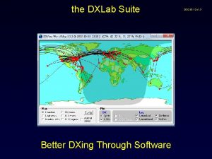
 Dxlab suite
 Treasury automation provider
 Suite crm ventajas y desventajas
