The Xray Imaging System Week 4 5 Bucky

The X-ray Imaging System Week 4 -5

Bucky slot cover § During fluoroscopy the Bucky tray is moved to the end of the table § This leaves an opening in the side of the table about 5 cm § Approximately at what level is the bucky?

Bucky slot cover • The opening should automatically be covered with at least 0. 25 mm Pb equiv. .

Fluoroscopy

The Control Console • The control console is device that allows the technologist to set technical factors (m. As & k. Vp) and to make an exposure. • Only a legally licensed individual is authorized to energize the console.

Control Panel • All the electric circuits connecting the meters and controls are at low voltage to minimize the possibility of shock.

Operating Console Controls: § Line Compensation, k. Vp, m. A and time § Quantity = # of x-rays § Milliroentges (m. R) or (m. R/m. As) § Quality = the pentrability § Kilovolts peak (k. Vp)

Operating Console has meters to measure § k. Vp, m. A, & exposure time § Modern units only display m. As § Units with ACE’s will have a separate meter for m. As

Control Panel

AEC § Automatic Exposure Control § Uses an ionization chamber § Technologist sets k. Vp, m. A, back-up time & sensors § Exposure terminates the IR has proper OD § Patient positioning must be absolutely accurate

AEC Sensors
 § Radiologic Technologist selects on the console")
APR § Anatomically Programmed Radiography (Ch 15) § Radiologic Technologist selects on the console a picture or a written description of the anatomic part to be imaged and the patient body habitus § A computer selects the appropriate k. Vp and m. As.

APR § The whole process uses an AEC § Precise patient positioning over the phototiming sensor is critical

APR

X-RAY CIRCUITY Contributions by Mosby, Thompson Publisher, Carlton, Bushberg, and the WWW.
 yellow • SECONDARY (HIGH VOLTAGE)")
3 Divisions of Circuit Board • PRIMARY (CONTROL PANEL) yellow • SECONDARY (HIGH VOLTAGE) blue • FILAMENT (LOW CURRENT) purple
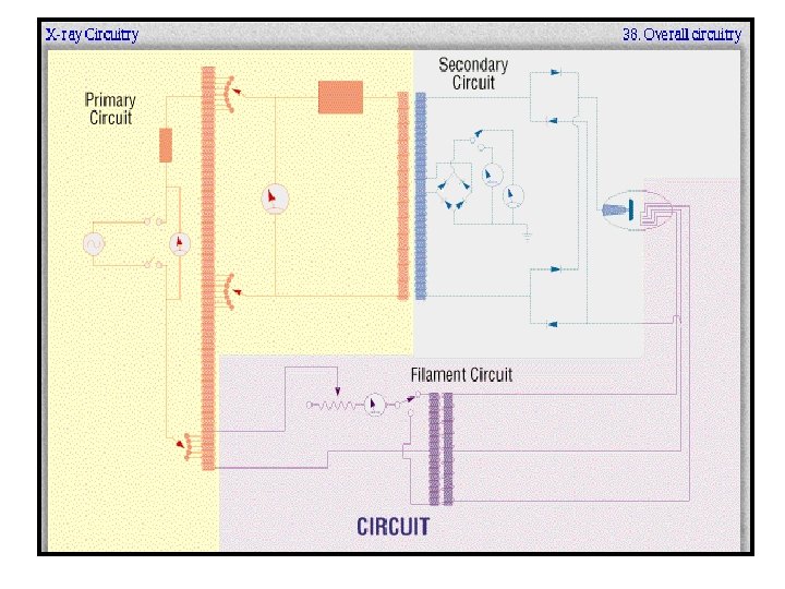
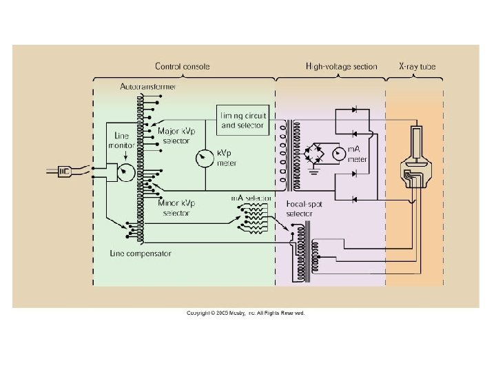

Functional Position Control Console Transformers Tube

Line Compensation § Most imaging systems are designed to operate on 220 V. (some 110 V or 440 V) § However power from the wall is not always accurate continuously

Line Compensation § Wired to the autotransformer is the line compensator § Designed to maintain the accurate voltage required for consistent production of high-quality images § Today’s line compensators are automatic and are not displayed on the control panel

Line Compensator

Autotransformer § The power for the x-ray imaging system is delivered first to the autotransformer § The autotransformer works on the principle of electromagnetic induction § It has one winding and one core § There a number of connections along its length

Autotransformer • A’s = primary connections & power into the transformer • Other connections allow for variations of voltages

Autotransformer § Is designed to step up voltage to about twice the input voltage value § The increase in voltage is directly related to the number of turns

k. Vp selection

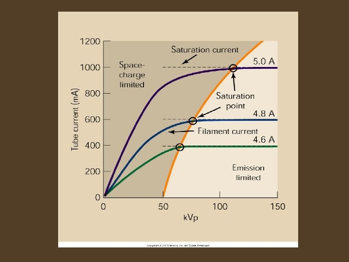
X-ray tube current or Filament circuit § A separate circuit crossing from cathode to anode § Measured in milliampers (m. A) § What determines how many x-rays are created?

X-ray tube current or Filament circuit § # of e- is determined by the temperature of the filament. The hotter the filament the more e§ Are their any limiting factors to thermionic emission?

m. A selection
")
Filaments Operate at currents of 3 to 6 amperes (A)

Question? What is directly proportional to the number of x-rays reaching the IR?

Exposure Timers § The timer circuit is separate from the other main circuits of the imaging system § It is a mechanical or electronic device whose action is to “make” and “break” the high voltage across the x-ray tube § This is done on the primary side of the high voltage transformer.

m. As Timers § Monitors the product of m. A and exposure time § Terminates the exposure when the desired m. As value is reached § Located on the secondary side of the high-voltage transformer since actual tube current must be monitored

m. As Timers § Designed to proved the highest m. A for the shortest exposure § Modern X-ray machines have falling-load generator § Automatically adjusts to the highest m. A at the shortest exposure time possible

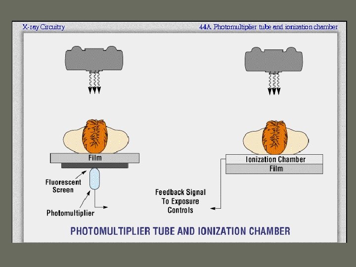
AEC Control § AEC measure the quantity of radiation reaching the IR § Automatically terminates when the IR has received enough radiation for desired OD § Two types are common

Flat, parallel plate ionization chamber § Located between the patient and the IR § Made radiolucent § Ionization w/in the chamber creates a charge; calibrated to produce a given OD on the IR
 detector assembly § Located behind the IR § Contains a fluorescent screen")
Photomultiplier (Photodiode) detector assembly § Located behind the IR § Contains a fluorescent screen and a photomultiplier § The photomultiplier detects the light from the fluorescent screen until the desired OD on the IR is reached terminating the exposure

AEC’s § Upon instillation must be calibrated by the service engineer § Technologists selects the desired OD which then sets the m. A & k. Vp

AEC’s § A back up timer usually automatically set to prevent over exposure if the AEC fails § Should be set to 1. 5 times the expected exposure time Why? § When the ionization chamber or photodiode reaches the preset level, a signal is returned to the operating console to terminate the exposure

High-Voltage Generator § Responsible for increasing the output voltage from the autotransformer to the k. Vp necessary for x-ray production § 3 parts: High-voltage transformer (stepup), filament transformer (step-down) and rectifiers

High voltage transformer § Or step up transformer § Connected to the Major and Minor k. Vp selector § Increases the volts from the autotransformer to kilovolts

Step Up Transformer

Voltage Rectification § Converts AC to DC current § During the negative cycle current can only flow from anode to cathode § E- must travel cathode to anode – DC current keeps e- traveling in the correct direction, cathode to anode § Attracted to the positive anode

Voltage Rectification

X-Ray Tube Circuit

Filament transformer § Or step down transformer § Reduces the current to the filament

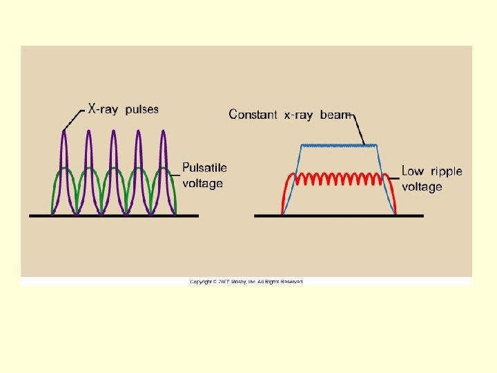
High-Voltage Generation – converts 220 volts of AC to kilovolts of DC l The generator is a FIXED component of the imaging system, not under the control of the technologist l Three basic types: single phase, three phase, and high frequency l The generator affects the quality and quantity of photons produced

How does this effect technique selection?

Questions on imaging systems?
- Slides: 52