
The World Leader in HighPerformance Signal Processing Solutions
- Slides: 50
The World Leader in High-Performance Signal Processing Solutions Direct Digital Synthesis Theory & Applications 1. Theory (why & how it works) 2. Error Sources 3. Advanced DDS Capabilities 4. Applications Examples paul. smith@analog. com
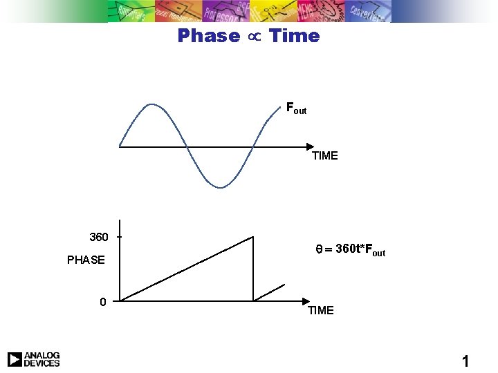
Phase µ Time Fout TIME 360 PHASE 0 q = 360 t*Fout TIME 1
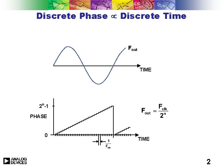
Discrete Phase µ Discrete Time Fout TIME 2 n-1 PHASE 0 TIME 2
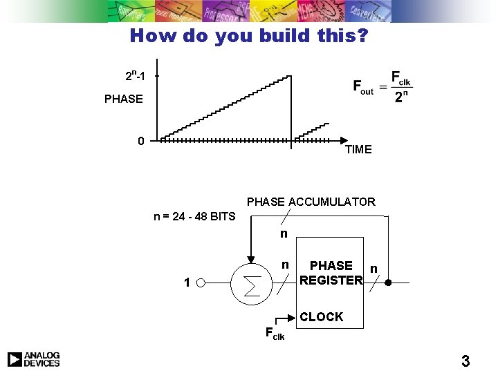
How do you build this? n 2 -1 PHASE 0 TIME PHASE ACCUMULATOR n = 24 - 48 BITS n n 1 PHASE n REGISTER CLOCK Fclk 3
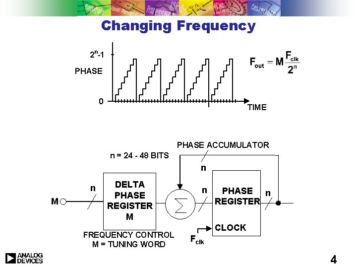
Changing Frequency n 2 -1 PHASE 0 TIME PHASE ACCUMULATOR n = 24 - 48 BITS n n M DELTA PHASE M REGISTER M FREQUENCY CONTROL M = TUNING WORD n PHASE n REGISTER CLOCK Fclk 4
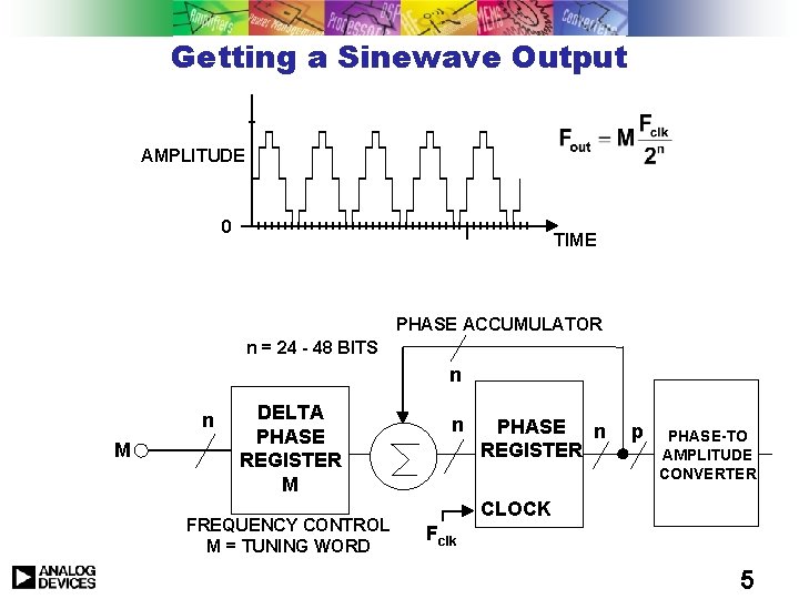
Getting a Sinewave Output AMPLITUDE 0 TIME PHASE ACCUMULATOR n = 24 - 48 BITS n n M DELTA PHASE REGISTER M FREQUENCY CONTROL M = TUNING WORD n PHASE n REGISTER p PHASE-TO AMPLITUDE CONVERTER CLOCK Fclk 5
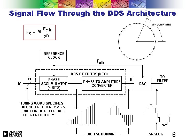
Signal Flow Through the DDS Architecture Fo = M Fclk 2 n REFERENCE CLOCK Fclk DDS CIRCUITRY (NCO) n M PHASE ACCUMULATOR (n-BITS) PHASE-TO-AMPLITUDE CONVERTER N DAC TO FILTER TUNING WORD SPECIFIES OUTPUT FREQUENCY AS A FRACTION OF REFERENCE CLOCK FREQUENCY DIGITAL DOMAIN ANALOG 6
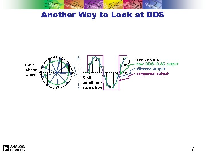
Another Way to Look at DDS 31 29 … … 4 3 2 1 0 63 … 6 -bit phase wheel … 4 2 0 5 -bit amplitude resolution vector data raw DDS-DAC output filtered output compared output 7
The World Leader in High-Performance Signal Processing Solutions Direct Digital Synthesis Theory & Applications 1. Theory (why & how it works) 2. Error Sources 3. Advanced DDS Capabilities 4. Applications Examples paul. smith@analog. com
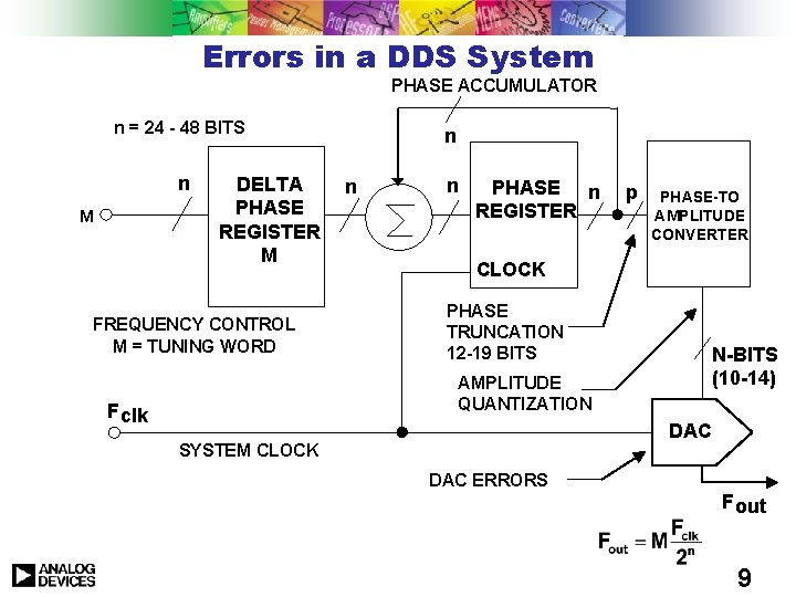
Errors in a DDS System PHASE ACCUMULATOR n = 24 - 48 BITS n M DELTA PHASE REGISTER M FREQUENCY CONTROL M = TUNING WORD n n n PHASE n REGISTER PHASE-TO AMPLITUDE CONVERTER CLOCK PHASE TRUNCATION 12 -19 BITS AMPLITUDE QUANTIZATION F clk p N-BITS (10 -14) DAC SYSTEM CLOCK DAC ERRORS F out 9
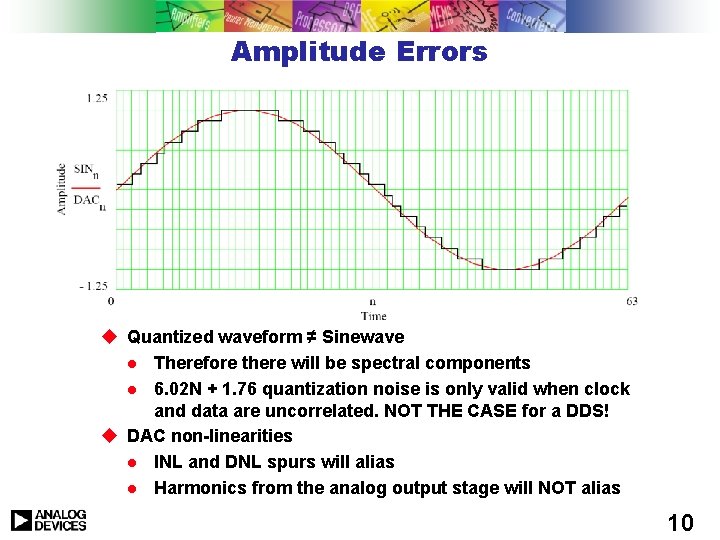
Amplitude Errors u Quantized waveform ≠ Sinewave l Therefore there will be spectral components l 6. 02 N + 1. 76 quantization noise is only valid when clock and data are uncorrelated. NOT THE CASE for a DDS! u DAC non-linearities l INL and DNL spurs will alias l Harmonics from the analog output stage will NOT alias 10
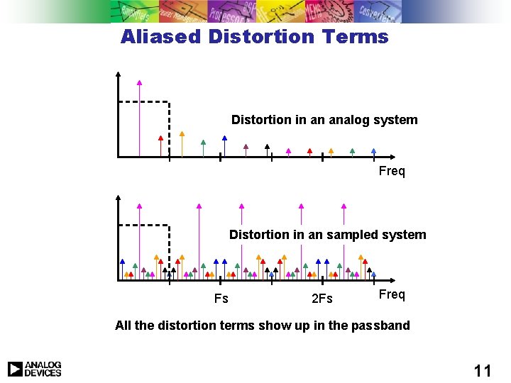
Aliased Distortion Terms Distortion in an analog system Freq Distortion in an sampled system Fs 2 Fs Freq All the distortion terms show up in the passband 11
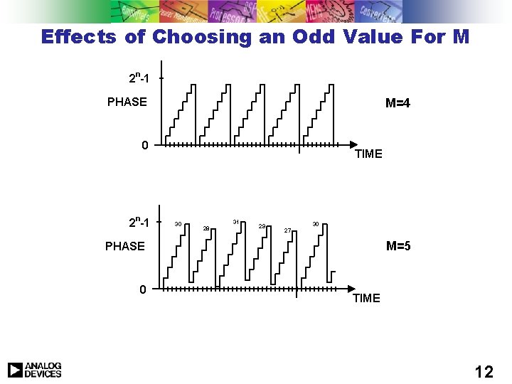
Effects of Choosing an Odd Value For M n 2 -1 M=4 PHASE 0 2 n-1 TIME 30 31 28 29 30 27 M=5 PHASE 0 TIME 12
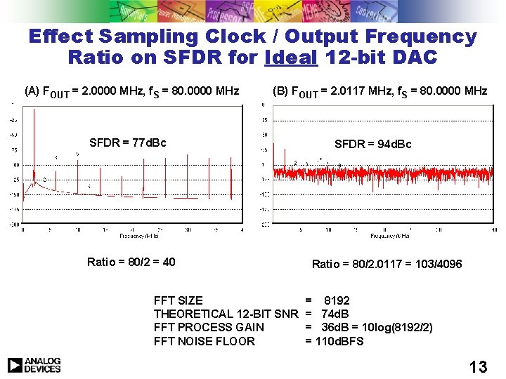
Effect Sampling Clock / Output Frequency Ratio on SFDR for Ideal 12 -bit DAC (A) FOUT = 2. 0000 MHz, f. S = 80. 0000 MHz (B) FOUT = 2. 0117 MHz, f. S = 80. 0000 MHz SFDR = 77 d. Bc Ratio = 80/2 = 40 FFT SIZE THEORETICAL 12 -BIT SNR FFT PROCESS GAIN FFT NOISE FLOOR SFDR = 94 d. Bc Ratio = 80/2. 0117 = 103/4096 = 8192 = 74 d. B = 36 d. B = 10 log(8192/2) = 110 d. BFS 13
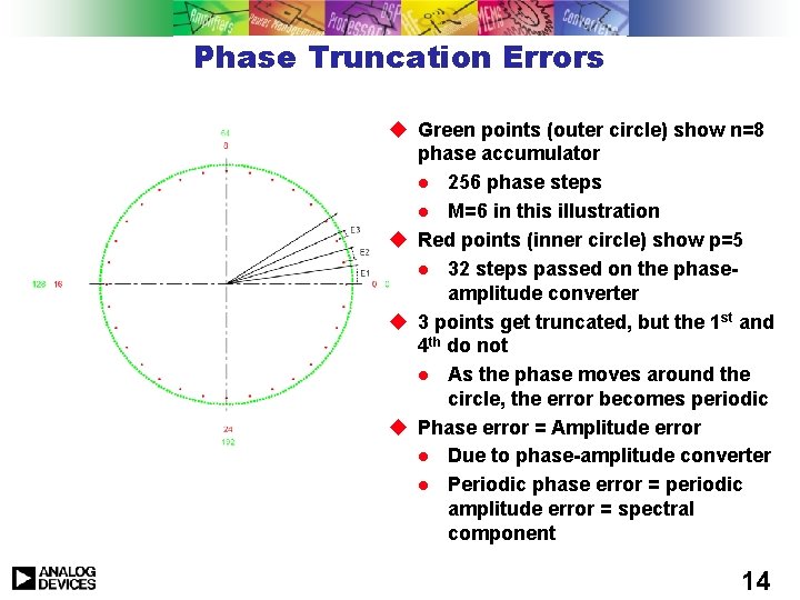
Phase Truncation Errors u Green points (outer circle) show n=8 phase accumulator l 256 phase steps l M=6 in this illustration u Red points (inner circle) show p=5 l 32 steps passed on the phaseamplitude converter u 3 points get truncated, but the 1 st and 4 th do not l As the phase moves around the circle, the error becomes periodic u Phase error = Amplitude error l Due to phase-amplitude converter l Periodic phase error = periodic amplitude error = spectral component 14
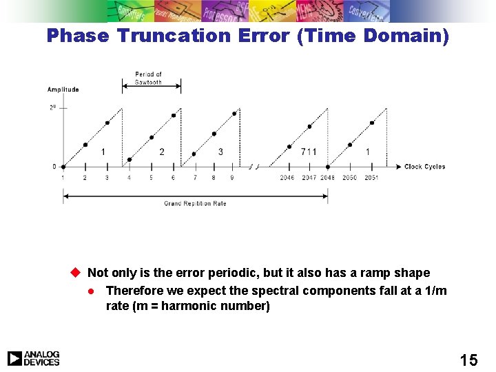
Phase Truncation Error (Time Domain) u Not only is the error periodic, but it also has a ramp shape l Therefore we expect the spectral components fall at a 1/m rate (m = harmonic number) 15
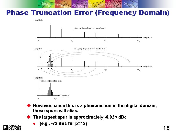
Phase Truncation Error (Frequency Domain) u However, since this is a phenomenon in the digital domain, these spurs will alias. u The largest spur is approximately -6. 02 p d. Bc l (e. g. , -72 d. Bc for p=12) 16
The World Leader in High-Performance Signal Processing Solutions Direct Digital Synthesis Theory & Applications 1. Theory (why & how it works) 2. Error Sources 3. Advanced DDS Capabilities 4. Applications Examples paul. smith@analog. com
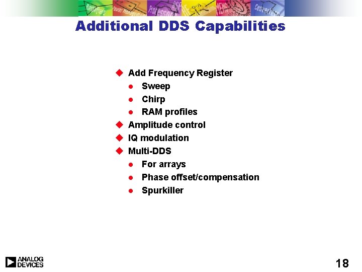
Additional DDS Capabilities u Add Frequency Register l Sweep l Chirp l RAM profiles u Amplitude control u IQ modulation u Multi-DDS l For arrays l Phase offset/compensation l Spurkiller 18
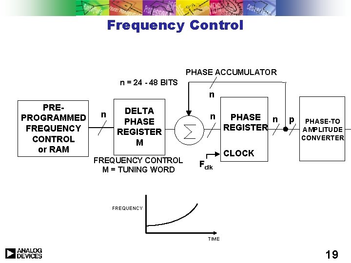
Frequency Control PHASE ACCUMULATOR n = 24 - 48 BITS n PREPROGRAMMED M FREQUENCY CONTROL or RAM n DELTA PHASE REGISTER M FREQUENCY CONTROL M = TUNING WORD n PHASE n REGISTER p PHASE-TO AMPLITUDE CONVERTER CLOCK Fclk FREQUENCY TIME 19
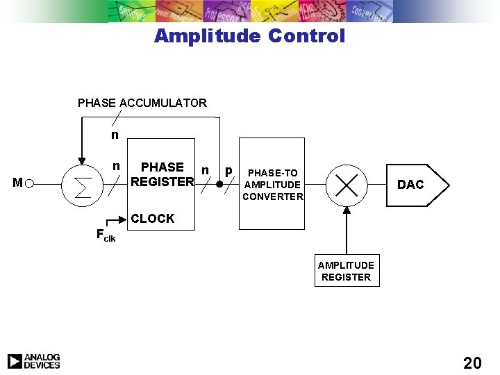
Amplitude Control PHASE ACCUMULATOR n n M PHASE n REGISTER p PHASE-TO AMPLITUDE CONVERTER DAC CLOCK Fclk AMPLITUDE REGISTER 20
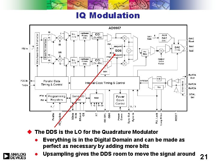
IQ Modulation u The DDS is the LO for the Quadrature Modulator l Everything is in the Digital Domain and can be made as perfect as necessary by adding more bits l Upsampling gives the DDS room to move the signal around 21
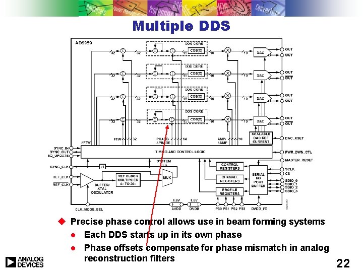
Multiple DDS u Precise phase control allows use in beam forming systems l Each DDS starts up in its own phase l Phase offsets compensate for phase mismatch in analog reconstruction filters 22
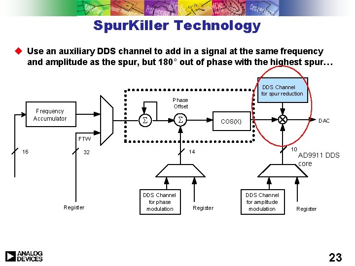
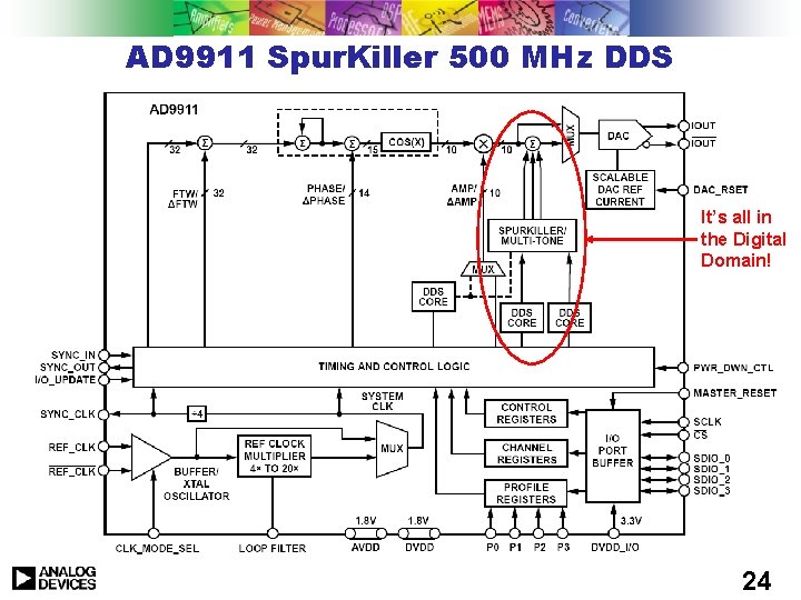
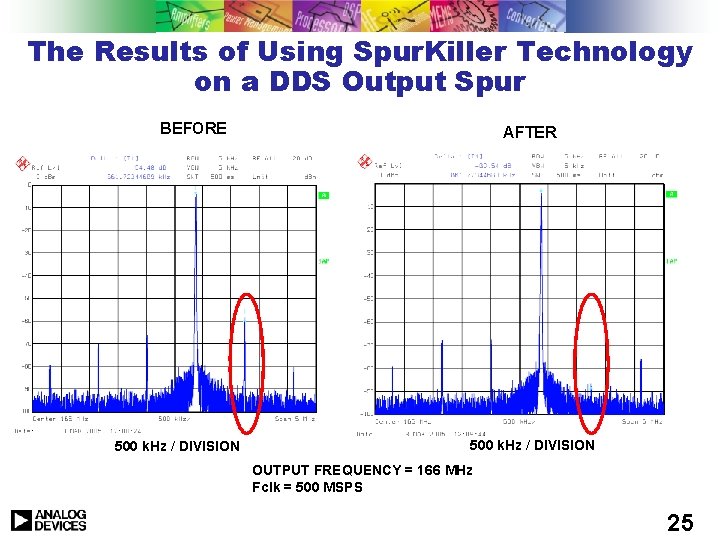
Spur. Killer Technology u Use an auxiliary DDS channel to add in a signal at the same frequency and amplitude as the spur, but 180° out of phase with the highest spur… DDS Channel for spur reduction Phase Offset Frequency Accumulator S S DAC COS(X) FTW 16 Register 10 14 32 DDS Channel for phase modulation Register DDS Channel for amplitude modulation AD 9911 DDS core Register 23
AD 9911 Spur. Killer 500 MHz DDS It’s all in the Digital Domain! 24
The Results of Using Spur. Killer Technology on a DDS Output Spur BEFORE 500 k. Hz / DIVISION AFTER 500 k. Hz / DIVISION OUTPUT FREQUENCY = 166 MHz Fclk = 500 MSPS 25
The World Leader in High-Performance Signal Processing Solutions Direct Digital Synthesis Theory & Applications 1. Theory (why & how it works) 2. Error Sources 3. Advanced DDS Capabilities 4. Applications Examples paul. smith@analog. com
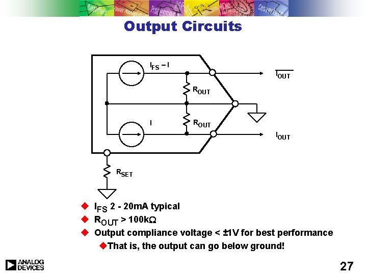
Output Circuits IFS – I IOUT ROUT IOUT RSET u u u IFS 2 - 20 m. A typical ROUT > 100 k Output compliance voltage < ± 1 V for best performance u. That is, the output can go below ground! 27
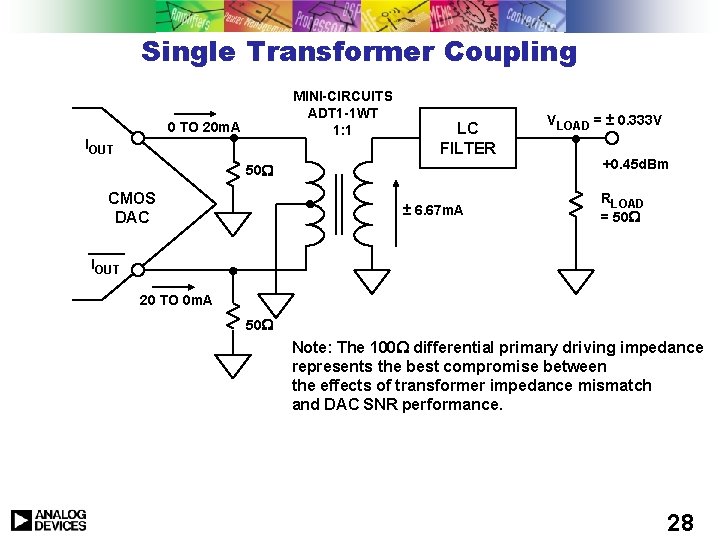
Single Transformer Coupling MINI-CIRCUITS ADT 1 -1 WT 1: 1 0 TO 20 m. A IOUT LC FILTER 50 CMOS DAC ± 6. 67 m. A VLOAD = ± 0. 333 V +0. 45 d. Bm RLOAD = 50 IOUT 20 TO 0 m. A 50 Note: The 100 differential primary driving impedance represents the best compromise between the effects of transformer impedance mismatch and DAC SNR performance. 28
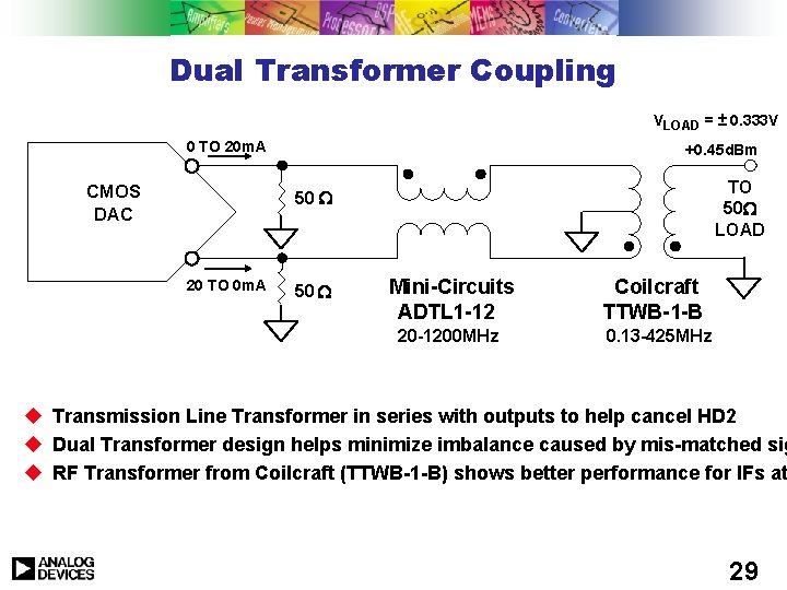
Dual Transformer Coupling VLOAD = ± 0. 333 V 0 TO 20 m. A CMOS DAC +0. 45 d. Bm TO 50 LOAD 50 20 TO 0 m. A 50 Mini-Circuits ADTL 1 -12 20 -1200 MHz Coilcraft TTWB-1 -B 0. 13 -425 MHz u Transmission Line Transformer in series with outputs to help cancel HD 2 u Dual Transformer design helps minimize imbalance caused by mis-matched sig u RF Transformer from Coilcraft (TTWB-1 -B) shows better performance for IFs at 29
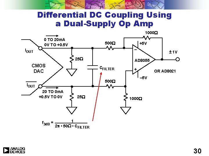
Differential DC Coupling Using a Dual-Supply Op Amp 1000 0 TO 20 m. A 0 V TO +0. 5 V 500 +5 V – IOUT 25 CMOS DAC AD 8055 CFILTER 500 IOUT 20 TO 0 m. A +0. 5 V TO 0 V f 3 d. B = 25 ± 1 V + OR AD 8021 – 5 V 1000 1 2 • 50 • CFILTER 30
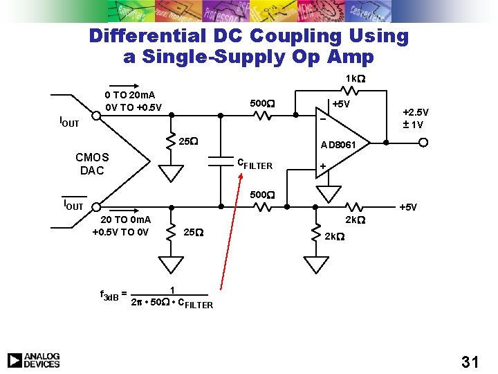
Differential DC Coupling Using a Single-Supply Op Amp 1 k 0 TO 20 m. A 0 V TO +0. 5 V 500 +5 V – IOUT 25 CMOS DAC +2. 5 V ± 1 V AD 8061 CFILTER + 500 IOUT +5 V 20 TO 0 m. A +0. 5 V TO 0 V f 3 d. B = 2 k 25 2 k 1 2 • 50 • CFILTER 31
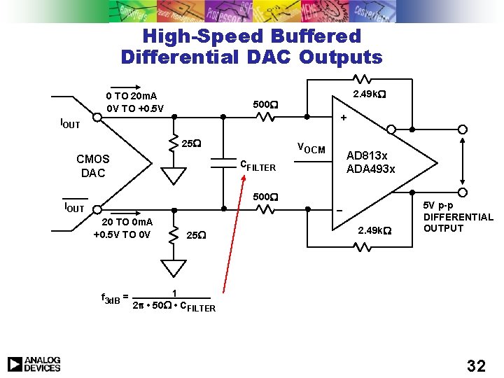
High-Speed Buffered Differential DAC Outputs 0 TO 20 m. A 0 V TO +0. 5 V 2. 49 k 500 + IOUT 25 CMOS DAC VOCM AD 813 x ADA 493 x CFILTER 500 IOUT – 20 TO 0 m. A +0. 5 V TO 0 V f 3 d. B = 25 2. 49 k 5 V p-p DIFFERENTIAL OUTPUT 1 2 • 50 • CFILTER 32
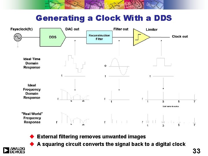
Generating a Clock With a DDS u External filtering removes unwanted images u A squaring circuit converts the signal back to a digital clock 33
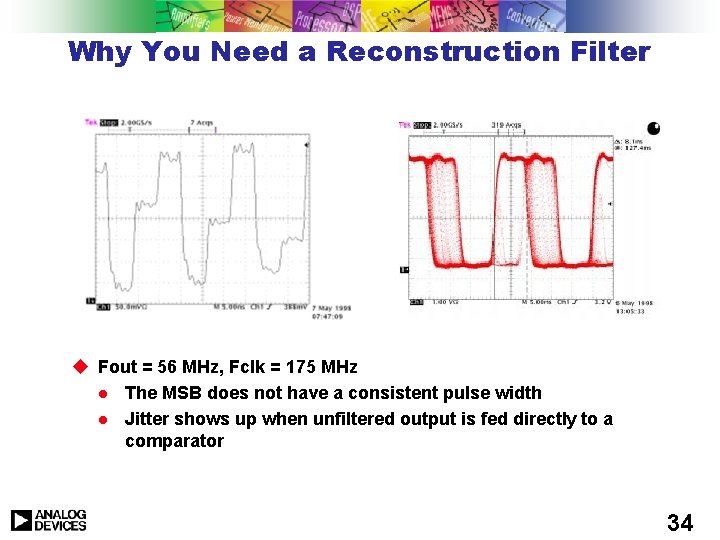
Why You Need a Reconstruction Filter u Fout = 56 MHz, Fclk = 175 MHz l The MSB does not have a consistent pulse width l Jitter shows up when unfiltered output is fed directly to a comparator 34
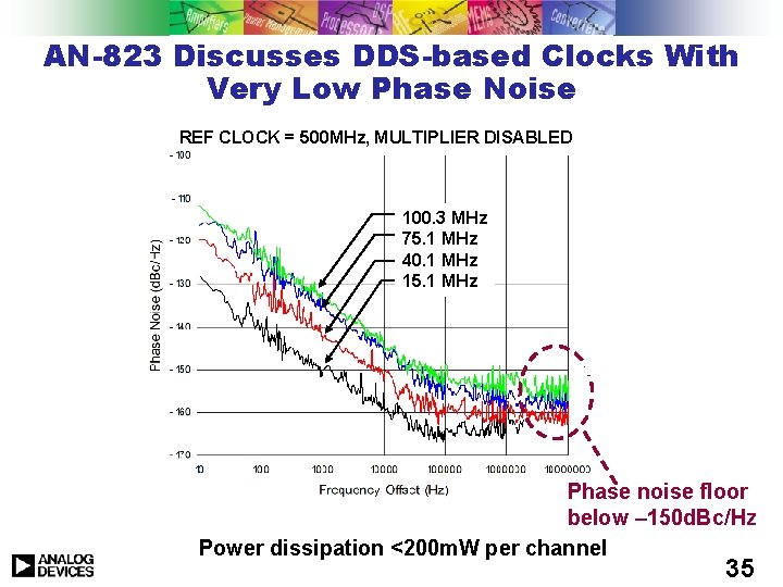
AN-823 Discusses DDS-based Clocks With Very Low Phase Noise REF CLOCK = 500 MHz, MULTIPLIER DISABLED 100. 3 MHz 15. 1 MHz 75. 1 40. 1 MHz 40. 1 75. 1 MHz 15. 1 100. 3 MHz Phase noise floor below – 150 d. Bc/Hz Power dissipation <200 m. W per channel 35
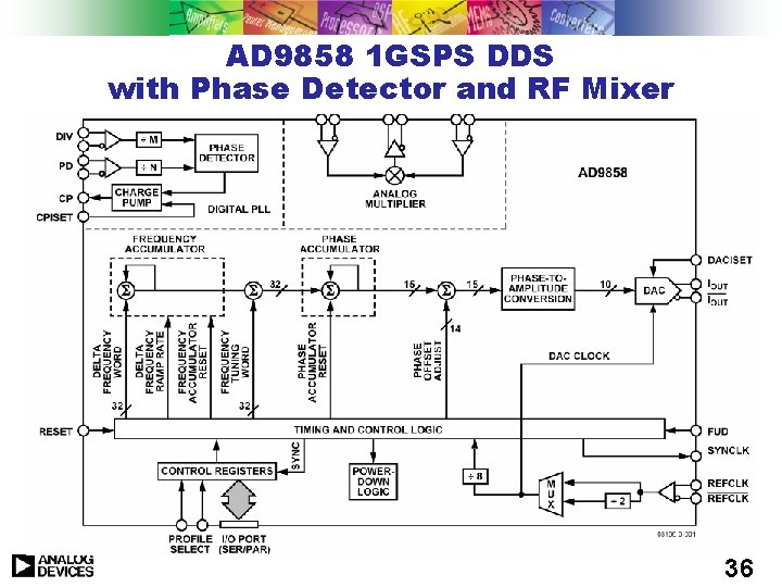
AD 9858 1 GSPS DDS with Phase Detector and RF Mixer 36
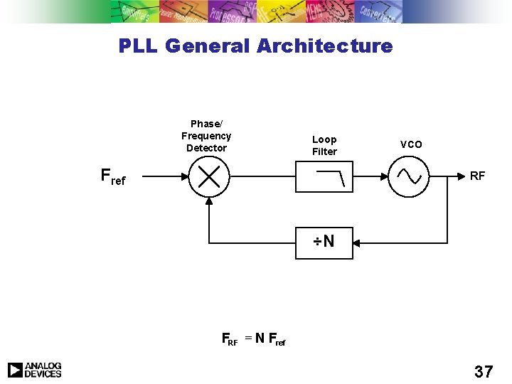
PLL General Architecture Phase/ Frequency Detector Loop Filter Fref VCO RF ÷N FRF = N Fref 37
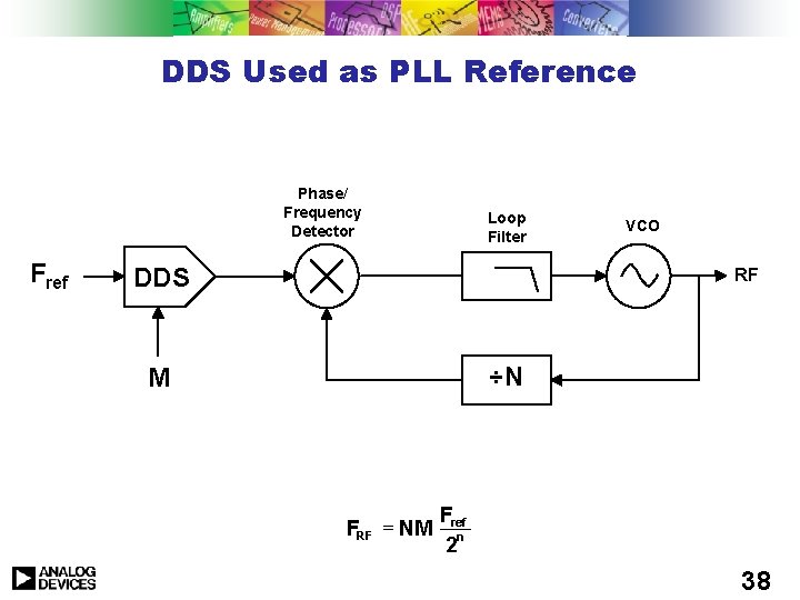
DDS Used as PLL Reference Phase/ Frequency Detector Fref Loop Filter DDS VCO RF ÷N M FRF = NM Fref 2 n 38
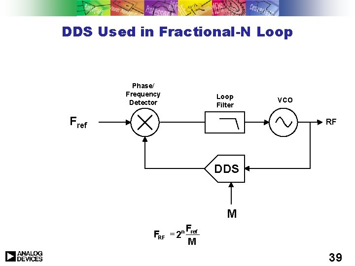
DDS Used in Fractional-N Loop Phase/ Frequency Detector Loop Filter Fref VCO RF DDS M FRF = 2 n Fref M 39
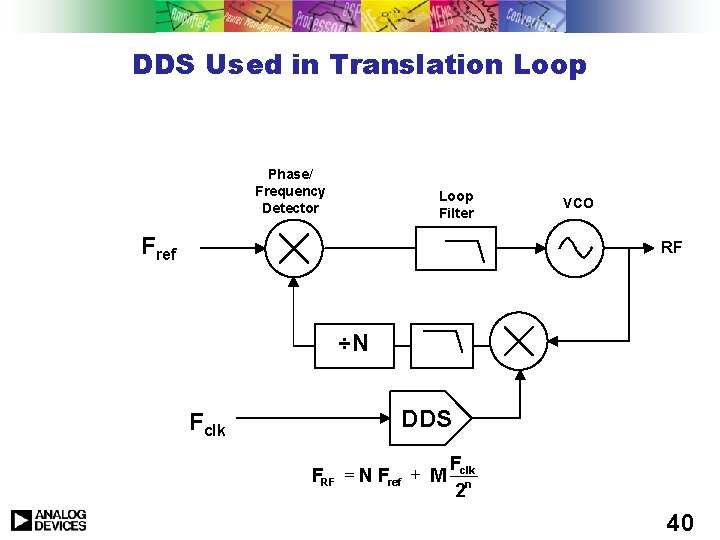
DDS Used in Translation Loop Phase/ Frequency Detector Loop Filter Fref VCO RF ÷N Fclk DDS F FRF = N Fref + M clk 2 n 40
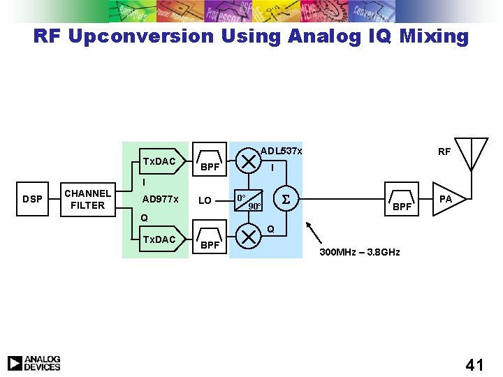
RF Upconversion Using Analog IQ Mixing Tx. DAC ADL 537 x BPF RF I I DSP CHANNEL FILTER AD 977 x LO Q Tx. DAC 0° 90° BPF PA Q BPF 300 MHz – 3. 8 GHz 41
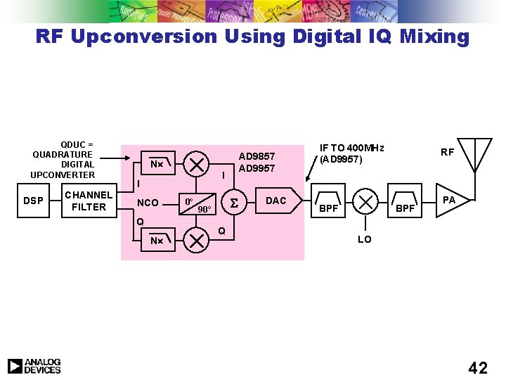
RF Upconversion Using Digital IQ Mixing QDUC = QUADRATURE DIGITAL UPCONVERTER DSP CHANNEL FILTER AD 9857 AD 9957 N I I NCO Q N 0° 90° Q DAC IF TO 400 MHz (AD 9957) BPF RF BPF PA LO 42
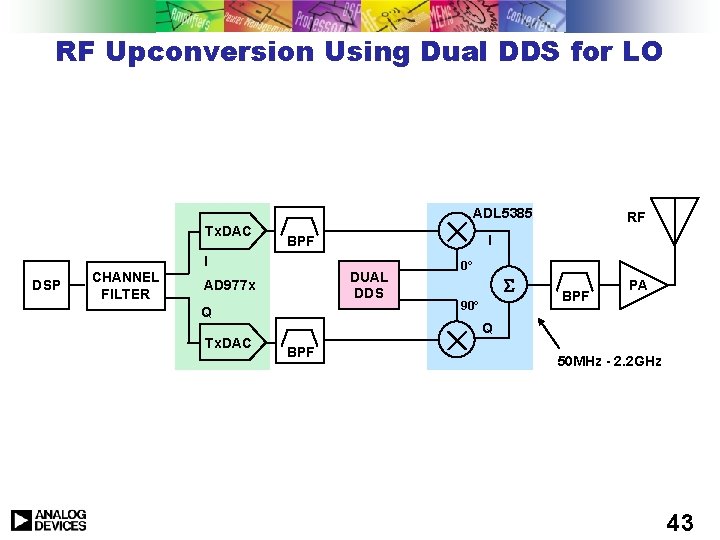
RF Upconversion Using Dual DDS for LO ADL 5385 Tx. DAC I BPF I DSP CHANNEL FILTER DUAL DDS AD 977 x Q Tx. DAC RF 0° 90° BPF PA Q BPF 50 MHz - 2. 2 GHz 43
On-Line DDS Tools ADIsim. DDS 44
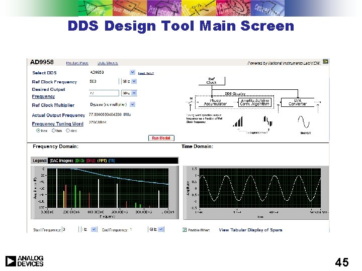
DDS Design Tool Main Screen 45
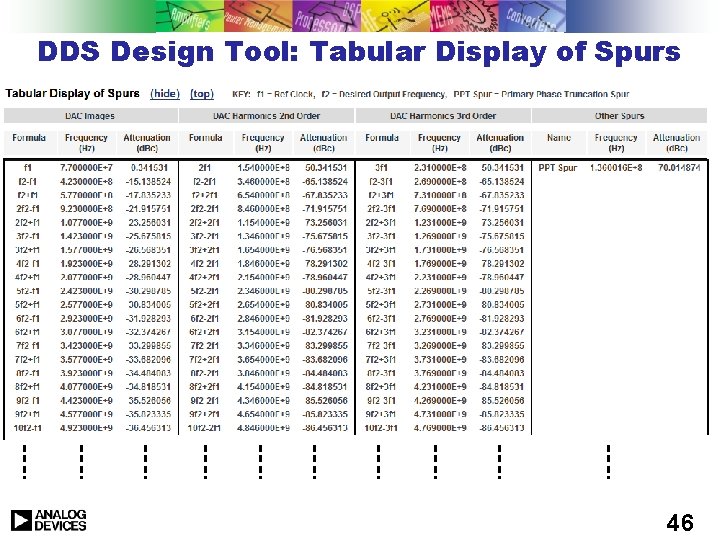
DDS Design Tool: Tabular Display of Spurs 46
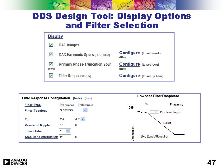
DDS Design Tool: Display Options and Filter Selection 47
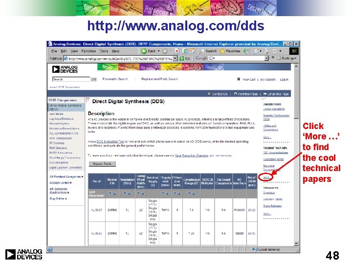
http: //www. analog. com/dds Click ‘More …’ to find the cool technical papers 48
Summary u DDS can be used to obtain a variety of precision waveforms u Compared to other frequency generating techniques, a DDS has the following advantages: l Precise phase control without affecting frequency l Precise frequency control without affecting phase l Fast arbitrary phase changes l Fast arbitrary frequency changes l Precision modulation u DDS has well known error characteristics u Care must be taken designing the output analog circuitry u Applications abound! ADI makes some GREAT parts 49