
The Super NEMO Tracker Manchester status Steve Snow





- Slides: 29
The Super. NEMO Tracker Manchester status Steve Snow Ray Thompson Stefan Soldner-Rembold Irina Nasteva James Mylroie-Smith Nasim Fatemi-Ghomi
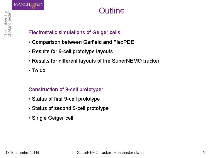
Outline Electrostatic simulations of Geiger cells: • Comparison between Garfield and Flex. PDE • Results for 9 -cell prototype layouts • Results for different layouts of the Super. NEMO tracker • To do… Construction of 9 -cell prototype: • Status of first 9 -cell prototype • Status of second 9 -cell prototype • Single Geiger cell 19 September 2006 Super. NEMO tracker, Manchester status 2
Electrostatic simulations of Geiger cells 3
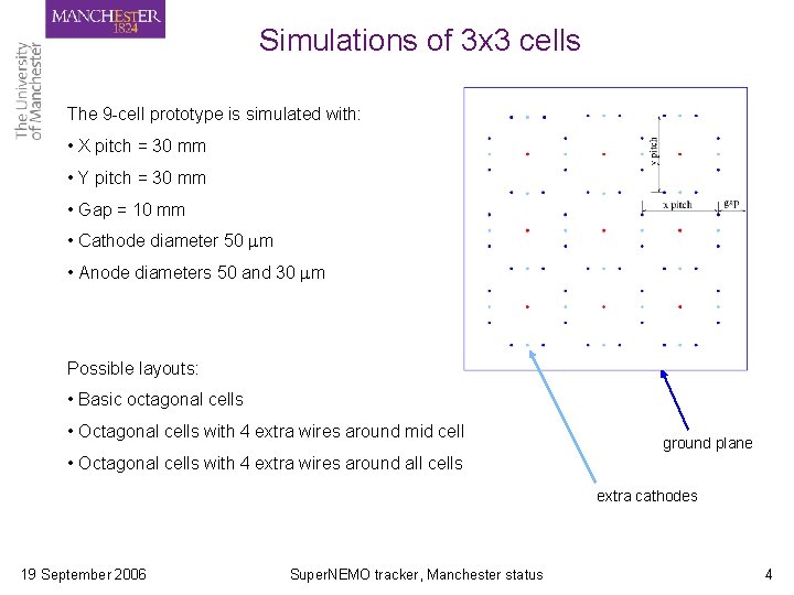
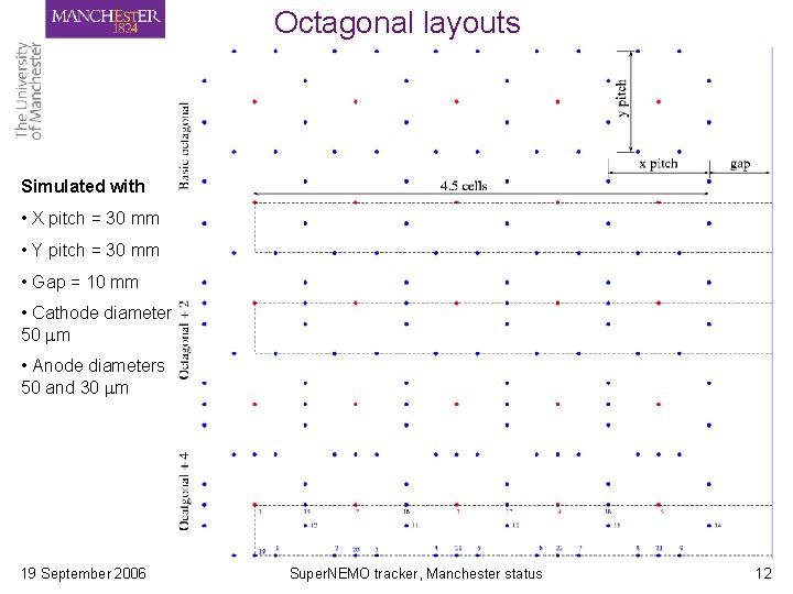
Simulations of 3 x 3 cells The 9 -cell prototype is simulated with: • X pitch = 30 mm • Y pitch = 30 mm • Gap = 10 mm • Cathode diameter 50 m • Anode diameters 50 and 30 m Possible layouts: • Basic octagonal cells • Octagonal cells with 4 extra wires around mid cell ground plane • Octagonal cells with 4 extra wires around all cells extra cathodes 19 September 2006 Super. NEMO tracker, Manchester status 4
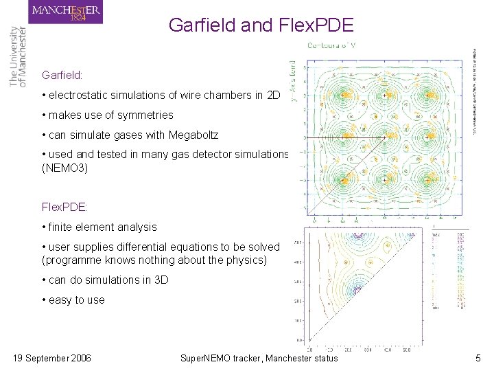
Garfield and Flex. PDE Garfield: • electrostatic simulations of wire chambers in 2 D • makes use of symmetries • can simulate gases with Megaboltz • used and tested in many gas detector simulations (NEMO 3) Flex. PDE: • finite element analysis • user supplies differential equations to be solved (programme knows nothing about the physics) • can do simulations in 3 D • easy to use 19 September 2006 Super. NEMO tracker, Manchester status 5
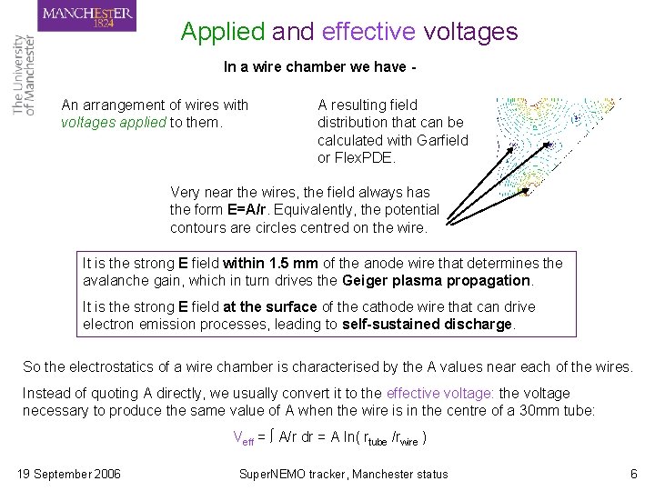
Applied and effective voltages In a wire chamber we have An arrangement of wires with voltages applied to them. A resulting field distribution that can be calculated with Garfield or Flex. PDE. Very near the wires, the field always has the form E=A/r. Equivalently, the potential contours are circles centred on the wire. It is the strong E field within 1. 5 mm of the anode wire that determines the avalanche gain, which in turn drives the Geiger plasma propagation. It is the strong E field at the surface of the cathode wire that can drive electron emission processes, leading to self-sustained discharge. So the electrostatics of a wire chamber is characterised by the A values near each of the wires. Instead of quoting A directly, we usually convert it to the effective voltage: the voltage necessary to produce the same value of A when the wire is in the centre of a 30 mm tube: Veff = ∫ A/r dr = A ln( rtube /rwire ) 19 September 2006 Super. NEMO tracker, Manchester status 6
Gain versus Voltage and Anode radius To compare layouts with different anode diameters we need to know how the Townsend coefficient a varies with E. We used predictions from Magboltz for the NEMO-3 gas mixture. The avalanche gain is given by integration of a(E) in the high field region: Gain = exp( ∫ a(A/r). dr ) The result of the integration for 30 and 50 micron wire diameters, at a range of effective voltages, is shown in this plot. This shows that a 50 micron wire with Veff = 1700 V will give the same gain as a 30 micron wire with Veff = 1654 V. 19 September 2006 Super. NEMO tracker, Manchester status 7
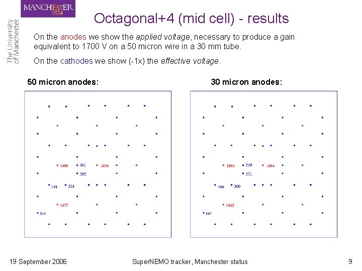
Basic octagonal 3 x 3 cells - results On the anodes we show the applied voltage, necessary to produce a gain equivalent to 1700 V on a 50 micron wire in a 30 mm tube. On the cathodes we show (-1 x) the effective voltage. 50 micron anodes: 19 September 2006 30 micron anodes: Super. NEMO tracker, Manchester status 8
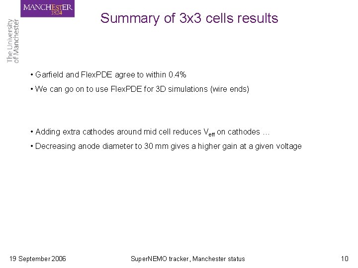
Octagonal+4 (mid cell) - results On the anodes we show the applied voltage, necessary to produce a gain equivalent to 1700 V on a 50 micron wire in a 30 mm tube. On the cathodes we show (-1 x) the effective voltage. 50 micron anodes: 19 September 2006 30 micron anodes: Super. NEMO tracker, Manchester status 9
Summary of 3 x 3 cells results • Garfield and Flex. PDE agree to within 0. 4% • We can go on to use Flex. PDE for 3 D simulations (wire ends) • Adding extra cathodes around mid cell reduces Veff on cathodes … • Decreasing anode diameter to 30 mm gives a higher gain at a given voltage 19 September 2006 Super. NEMO tracker, Manchester status 10
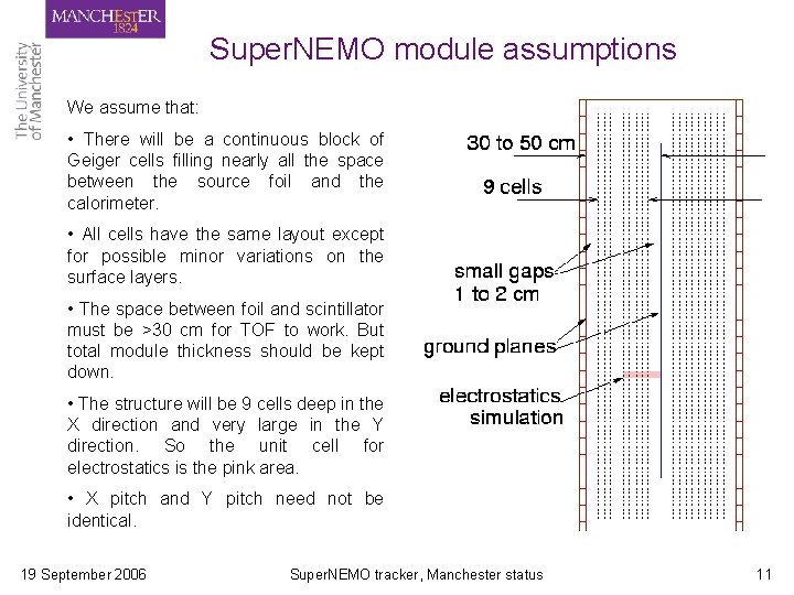
Super. NEMO module assumptions We assume that: • There will be a continuous block of Geiger cells filling nearly all the space between the source foil and the calorimeter. • All cells have the same layout except for possible minor variations on the surface layers. • The space between foil and scintillator must be >30 cm for TOF to work. But total module thickness should be kept down. • The structure will be 9 cells deep in the X direction and very large in the Y direction. So the unit cell for electrostatics is the pink area. • X pitch and Y pitch need not be identical. 19 September 2006 Super. NEMO tracker, Manchester status 11
Octagonal layouts Simulated with • X pitch = 30 mm • Y pitch = 30 mm • Gap = 10 mm • Cathode diameter 50 m • Anode diameters 50 and 30 m 19 September 2006 Super. NEMO tracker, Manchester status 12
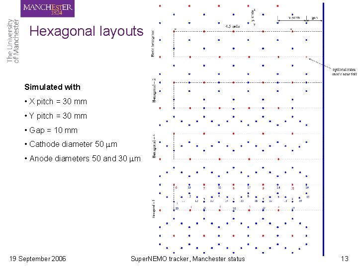
Hexagonal layouts Simulated with • X pitch = 30 mm • Y pitch = 30 mm • Gap = 10 mm • Cathode diameter 50 m • Anode diameters 50 and 30 m 19 September 2006 Super. NEMO tracker, Manchester status 13
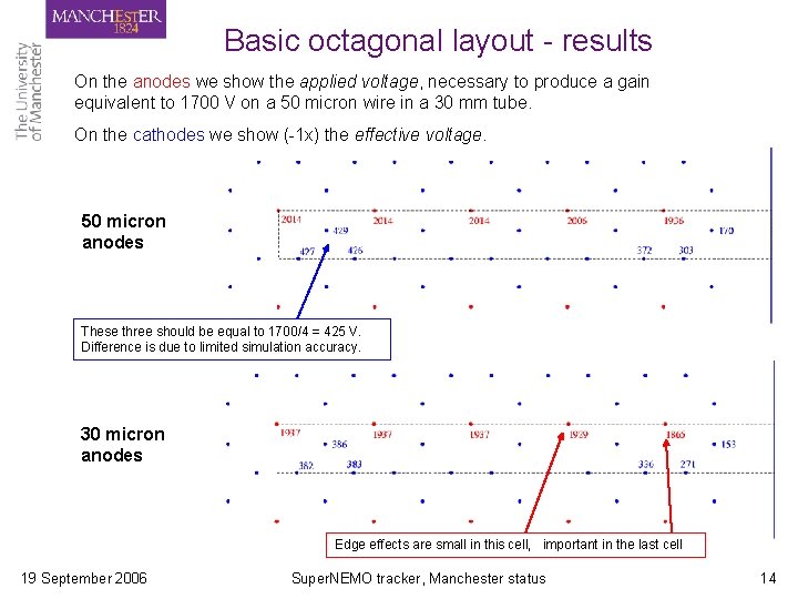
Basic octagonal layout - results On the anodes we show the applied voltage, necessary to produce a gain equivalent to 1700 V on a 50 micron wire in a 30 mm tube. On the cathodes we show (-1 x) the effective voltage. 50 micron anodes These three should be equal to 1700/4 = 425 V. Difference is due to limited simulation accuracy. 30 micron anodes Edge effects are small in this cell, important in the last cell 19 September 2006 Super. NEMO tracker, Manchester status 14
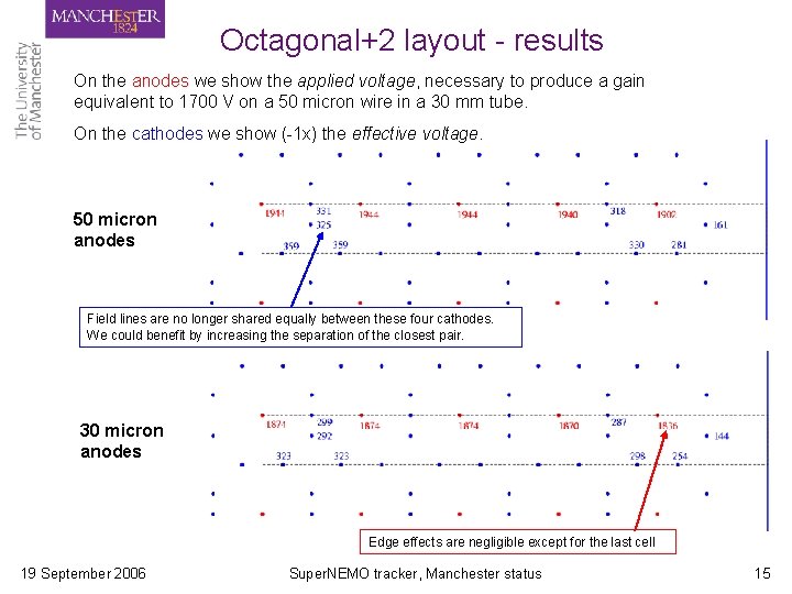
Octagonal+2 layout - results On the anodes we show the applied voltage, necessary to produce a gain equivalent to 1700 V on a 50 micron wire in a 30 mm tube. On the cathodes we show (-1 x) the effective voltage. 50 micron anodes Field lines are no longer shared equally between these four cathodes. We could benefit by increasing the separation of the closest pair. 30 micron anodes Edge effects are negligible except for the last cell 19 September 2006 Super. NEMO tracker, Manchester status 15
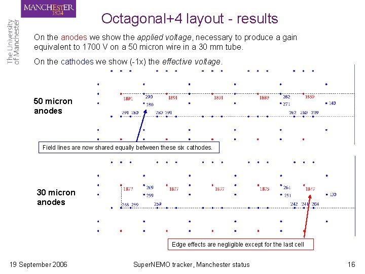
Octagonal+4 layout - results On the anodes we show the applied voltage, necessary to produce a gain equivalent to 1700 V on a 50 micron wire in a 30 mm tube. On the cathodes we show (-1 x) the effective voltage. 50 micron anodes Field lines are now shared equally between these six cathodes. 30 micron anodes Edge effects are negligible except for the last cell 19 September 2006 Super. NEMO tracker, Manchester status 16
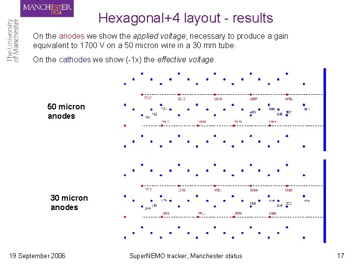
Hexagonal+4 layout - results On the anodes we show the applied voltage, necessary to produce a gain equivalent to 1700 V on a 50 micron wire in a 30 mm tube. On the cathodes we show (-1 x) the effective voltage. 50 micron anodes 30 micron anodes 19 September 2006 Super. NEMO tracker, Manchester status 17
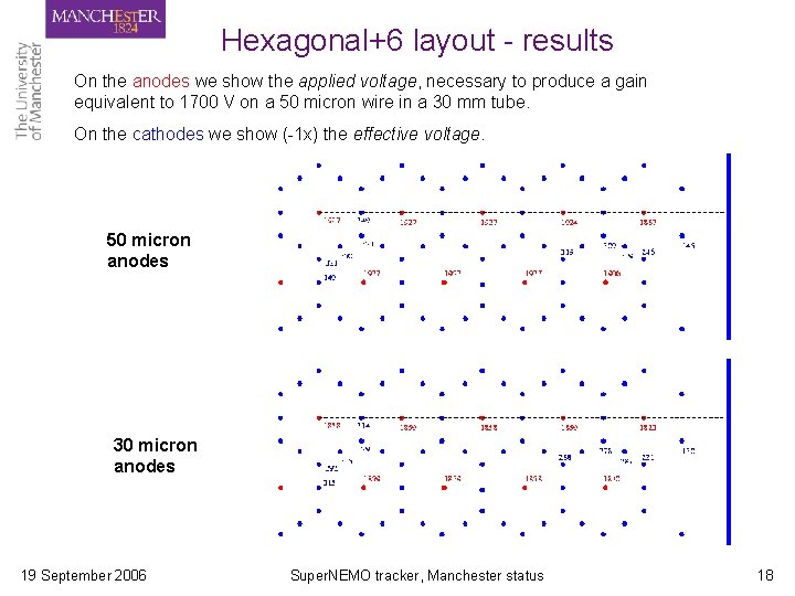
Hexagonal+6 layout - results On the anodes we show the applied voltage, necessary to produce a gain equivalent to 1700 V on a 50 micron wire in a 30 mm tube. On the cathodes we show (-1 x) the effective voltage. 50 micron anodes 30 micron anodes 19 September 2006 Super. NEMO tracker, Manchester status 18
Figures of merit We want: wires/cm to be small for transparency, cathode Veff to be small for stability. The dominant parameter is cathodes/cell, followed by anode diameter, then Hex/Oct. We choose the octagonal as our baseline design. 19 September 2006 Super. NEMO tracker, Manchester status 19
To do … Geiger cells: • Simulate the NEMO 3 cell to give an estimate of tolerable cathode Veff. • Check a handful of points on the gain versus voltage and anode diameter plots by operating a test cell in proportional mode. • Check whether Geiger propagation depends only on gain, as assumed, or whether it has some extra dependence on wire diameter. • Find out experimentally the highest tolerable cathode surface field a) on a fresh wire, b) after some ageing. Physics simulation: • Are 40 mm cells are acceptable for two-track resolution? • Which of the following have most influence on acceptance of 0 vbb events? energy loss or multiple scattering, in the gas or in wires, wire length, source foil area, foil-to-scintillator distance, … • This was partially studied by Darren Price, could be a new student project 19 September 2006 Super. NEMO tracker, Manchester status 20
Construction of 9 -cell tracker prototype 21
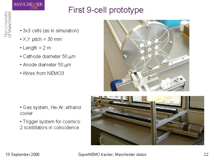
First 9 -cell prototype • 3 x 3 cells (as in simulation) • X, Y pitch = 30 mm • Length = 2 m • Cathode diameter 50 m • Anode diameter 50 m • Wires from NEMO 3 • Gas system, He-Ar, ethanol cooler • Trigger system for cosmics: 2 scintillators in coincidence 19 September 2006 Super. NEMO tracker, Manchester status 22
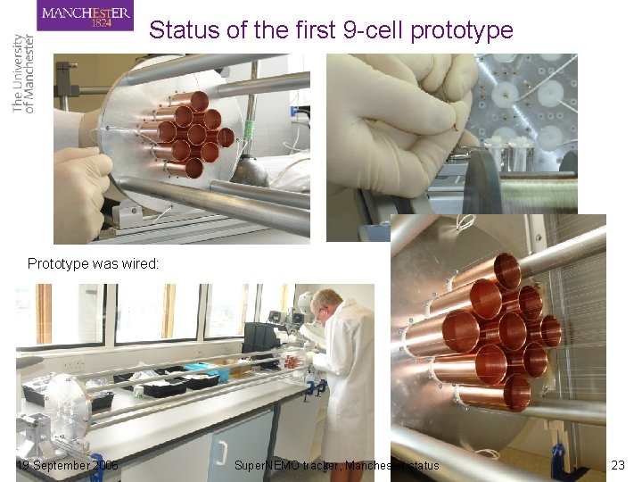
Status of the first 9 -cell prototype Prototype was wired: 19 September 2006 Super. NEMO tracker, Manchester status 23
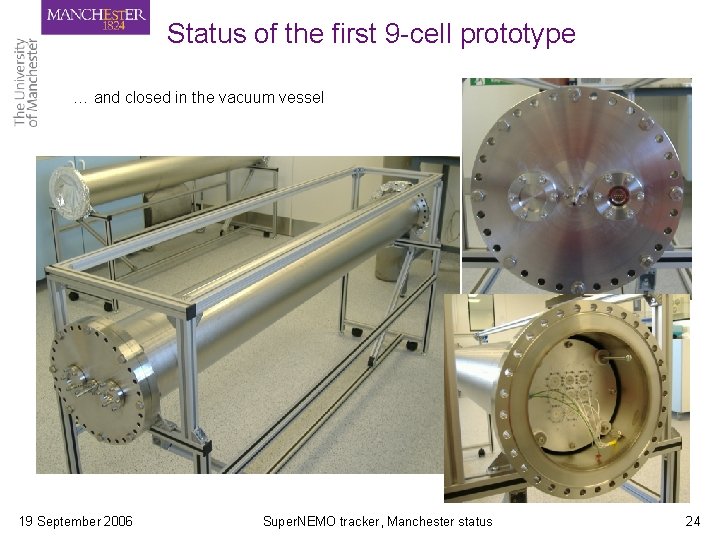
Status of the first 9 -cell prototype … and closed in the vacuum vessel 19 September 2006 Super. NEMO tracker, Manchester status 24
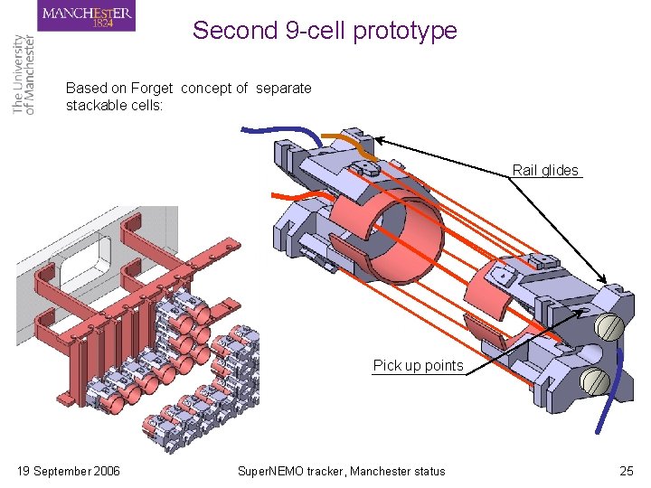
Second 9 -cell prototype Based on Forget concept of separate stackable cells: Rail glides Pick up points 19 September 2006 Super. NEMO tracker, Manchester status 25
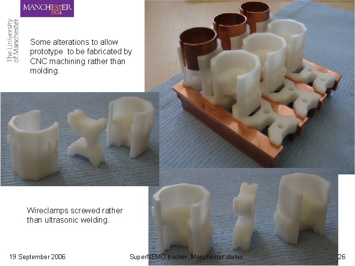
Some alterations to allow prototype to be fabricated by CNC machining rather than molding. Wireclamps screwed rather than ultrasonic welding. 19 September 2006 Super. NEMO tracker, Manchester status 26
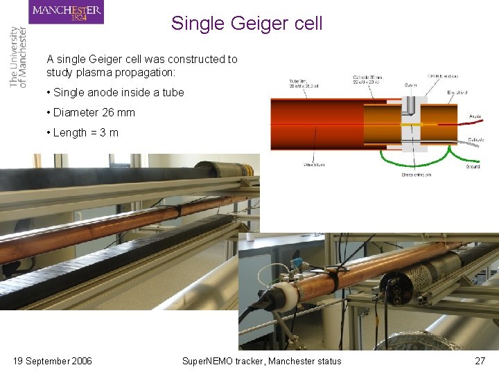
Single Geiger cell A single Geiger cell was constructed to study plasma propagation: • Single anode inside a tube • Diameter 26 mm • Length = 3 m 19 September 2006 Super. NEMO tracker, Manchester status 27
Single cell tests • He-Ar gas mixture, no alcohol yet • Trigger on 2 scintillators • We have seen the first signals 19 September 2006 Super. NEMO tracker, Manchester status 28
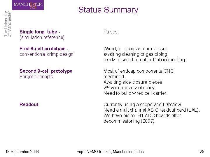
Status Summary Single long tube (simulation reference) Pulses. First 9 -cell prototype conventional crimp design Wired, in clean vacuum vessel. awaiting cleaning of gas piping. ready to switch on after Dubna meeting. Second 9 -cell prototype Forget concepts Most of endcap components CNC machined. Awaiting side closure pieces. 2 nd vacuum vessel ready. Need to build wired cell carrier. Readout Currently using a scope and Lab. View. Need a multichannel ASIC readout card (LAL). We have bid for H 1 ADC boards after decommissioning (2007). 19 September 2006 Super. NEMO tracker, Manchester status 29