
The RF system for FCCee A Butterworth CERN

The RF system for FCC-ee A. Butterworth, CERN Thanks to: O. Brunner, R. Calaga, E. Jensen, E. Montesinos, F. Zimmermann (CERN), U. Wienands (SLAC)
Outline •

Future Circular Collider Study - SCOPE CDR and cost review for the next ESU (2018) Forming an international collaboration to study: • pp-collider (FCC-hh) main emphasis, defining infrastructure requirements ~16 T 100 Te. V pp in 100 km • 80 -100 km infrastructure in Geneva area • e+e- collider (FCC-ee) as potential intermediate step • p-e (FCC-he) option F. Zimmermann
Physics requirements for FCC-ee F. Zimmermann
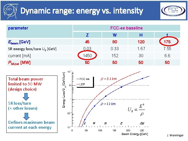
Dynamic range: energy vs. intensity parameter FCC-ee baseline Z W H t 45 80 120 175 SR energy loss/turn U 0 [Ge. V] 0. 03 0. 33 1. 67 7. 55 current [m. A] 1450 152 30 6. 6 PSR, tot [MW] 50 50 Ebeam [Ge. V] Total beam power limited to 50 MW (design choice) r = 3. 1 km SR loss/turn (+ other losses) r = 11 km Defines maximum beam current at each energy J. Wenninger
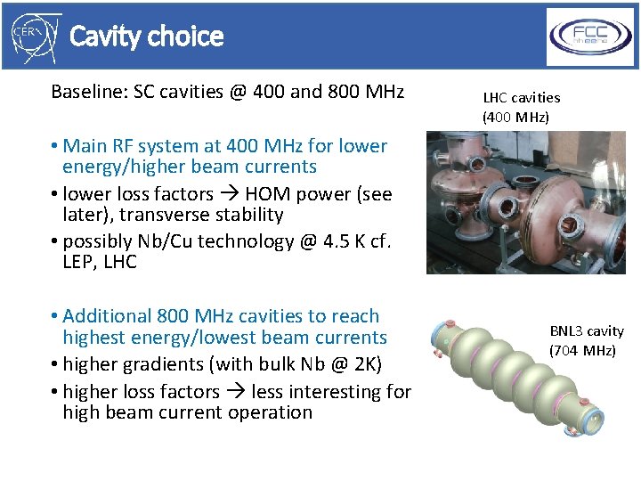
Cavity choice Baseline: SC cavities @ 400 and 800 MHz LHC cavities (400 MHz) • Main RF system at 400 MHz for lower energy/higher beam currents • lower loss factors HOM power (see later), transverse stability • possibly Nb/Cu technology @ 4. 5 K cf. LEP, LHC • Additional 800 MHz cavities to reach highest energy/lowest beam currents • higher gradients (with bulk Nb @ 2 K) • higher loss factors less interesting for high beam current operation BNL 3 cavity (704 MHz)

400 MHz cavity options R. Calaga • 400 MHz SC cavities with 1, 2 or 4 cells considered • 4 cells better for “real estate” gradient • Single cell has lowest HOM loss factor 2 cells a compromise

Cryomodule layout options Collaboration with Uni. Rostock: e. m. & thermal simulations

FCC-ee RF staging 4 values of beam energy, 3 RF configurations Ph. Lebrun FCC I&O meeting 150225 9

FCC-ee RF layout (per ring) L B A K C J D I E H Ph. Lebrun G FCC I&O meeting 150225 F 10

Alternative (400 MHz only) scenario 96 m 2 x 16 cryomodules 400 MHz 2 x 2 klystrons Displace modules to share between the 2 beams 96 m 32 cryomodules 400 MHz 4 klystrons
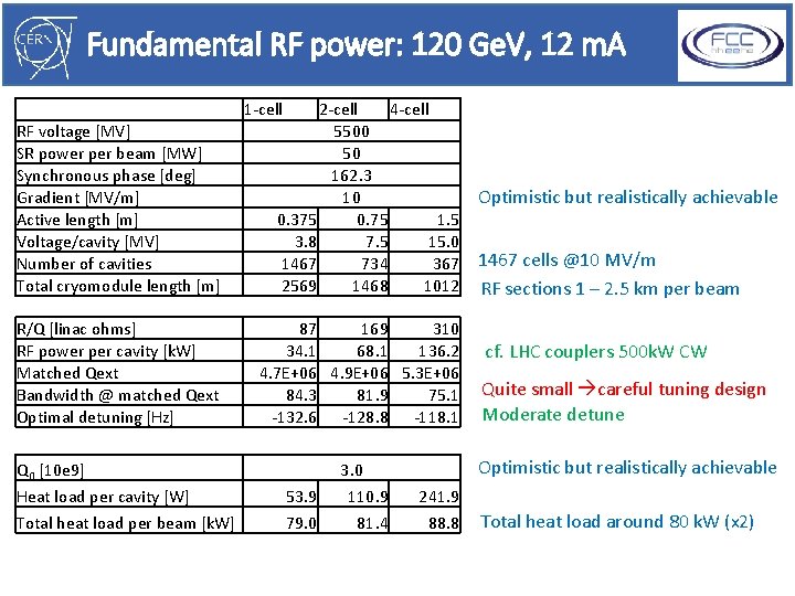
Fundamental RF power: 120 Ge. V, 12 m. A 1 -cell RF voltage [MV] SR power per beam [MW] Synchronous phase [deg] Gradient [MV/m] Active length [m] Voltage/cavity [MV] Number of cavities Total cryomodule length [m] 2 -cell 4 -cell 5500 50 162. 3 10 0. 375 0. 75 1. 5 3. 8 7. 5 15. 0 1467 734 367 2569 1468 1012 R/Q [linac ohms] RF power per cavity [k. W] Matched Qext Bandwidth @ matched Qext Optimal detuning [Hz] 87 169 310 34. 1 68. 1 136. 2 4. 7 E+06 4. 9 E+06 5. 3 E+06 84. 3 81. 9 75. 1 -132. 6 -128. 8 -118. 1 Q 0 [10 e 9] Heat load per cavity [W] Total heat load per beam [k. W] 53. 9 79. 0 3. 0 110. 9 81. 4 Optimistic but realistically achievable 1467 cells @10 MV/m RF sections 1 – 2. 5 km per beam cf. LHC couplers 500 k. W CW Quite small careful tuning design Moderate detune Optimistic but realistically achievable 241. 9 88. 8 Total heat load around 80 k. W (x 2)
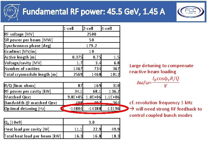
Fundamental RF power: 45. 5 Ge. V, 1. 45 A 1 -cell RF voltage [MV] SR power per beam [MW] Synchronous phase [deg] Gradient [MV/m] Active length [m] Voltage/cavity [MV] Number of cavities Total cryomodule length [m] 2 -cell 4 -cell 2500 50 179. 2 10 0. 375 0. 75 1. 7 3. 4 6. 8 1467 734 367 2569 1468 1012 R/Q [linac ohms] RF power per cavity [k. W] Matched Qext Bandwidth @ matched Qext Optimal detuning [Hz] 87 169 310 34. 1 68. 1 136. 2 9. 8 E+05 1. 0 E+06 1. 1 E+06 408 397 364 -14804 -14388 -13196 Q 0 [10 e 9] Heat load per cavity [W] Total heat load per beam [k. W] 11. 1 16. 3 3. 0 22. 9 16. 8 49. 9 18. 3 Large detuning to compensate reactive beam loading cf. revolution frequency 3 k. Hz will need strong RF feedback to control coupled bunch modes
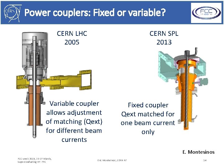
Power couplers: Fixed or variable? CERN LHC 2005 CERN SPL 2013 Variable coupler allows adjustment of matching (Qext) for different beam currents Fixed coupler Qext matched for one beam current only E. Montesinos FCC week 2015, 23 -27 March, Superconducting RF: FPC Eric Montesinos, CERN RF 14
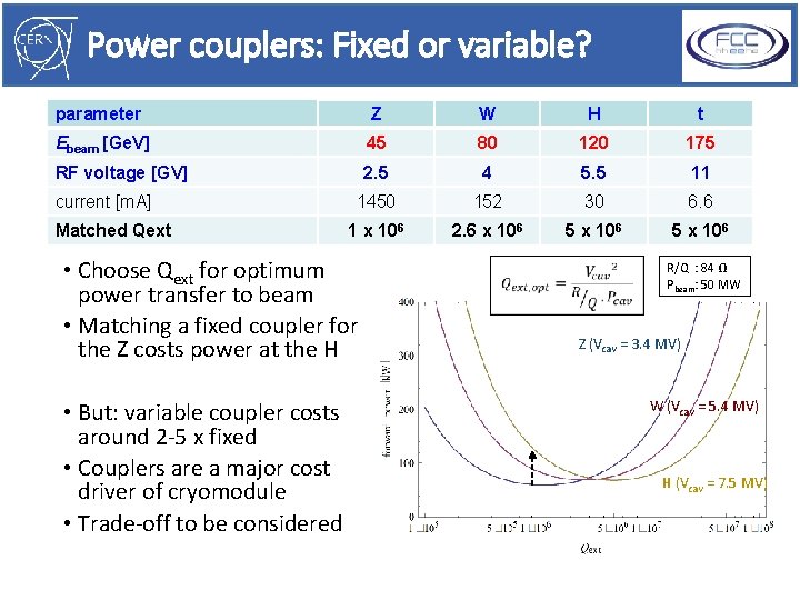
Power couplers: Fixed or variable? parameter Z W H t Ebeam [Ge. V] 45 80 120 175 RF voltage [GV] 2. 5 4 5. 5 11 1450 152 30 6. 6 1 x 10⁶ 2. 6 x 10⁶ 5 x 10⁶ current [m. A] Matched Qext • Choose Qext for optimum power transfer to beam • Matching a fixed coupler for the Z costs power at the H • But: variable coupler costs around 2 -5 x fixed • Couplers are a major cost driver of cryomodule • Trade-off to be considered R/Q : 84 Ω Pbeam: 50 MW Z (Vcav = 3. 4 MV) W (Vcav = 5. 4 MV) H (Vcav = 7. 5 MV)
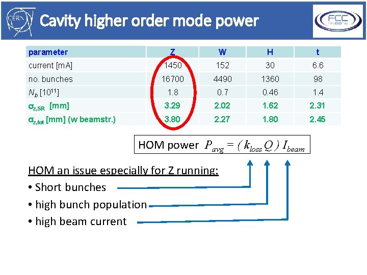
Cavity higher order mode power parameter Z W H t current [m. A] 1450 152 30 6. 6 no. bunches 16700 4490 1360 98 Nb [1011] 1. 8 0. 7 0. 46 1. 4 sz, SR [mm] 3. 29 2. 02 1. 62 2. 31 sz, tot [mm] (w beamstr. ) 3. 80 2. 27 1. 80 2. 45 HOM power Pavg = ( kloss Q ) Ibeam HOM an issue especially for Z running: • Short bunches • high bunch population • high beam current
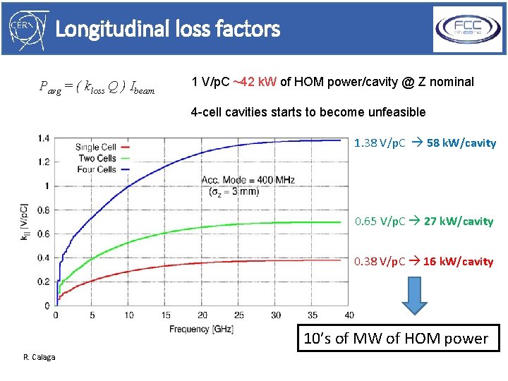
Longitudinal loss factors Pavg = ( kloss Q ) Ibeam 1 V/p. C ~42 k. W of HOM power/cavity @ Z nominal 4 -cell cavities starts to become unfeasible 1. 38 V/p. C 58 k. W/cavity 0. 65 V/p. C 27 k. W/cavity 0. 38 V/p. C 16 k. W/cavity 10’s of MW of HOM power R. Calaga
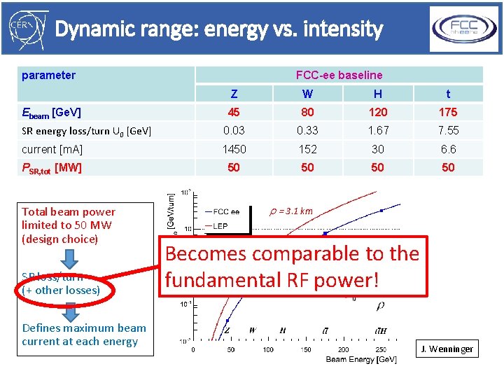
Dynamic range: energy vs. intensity parameter FCC-ee baseline Z W H t 45 80 120 175 SR energy loss/turn U 0 [Ge. V] 0. 03 0. 33 1. 67 7. 55 current [m. A] 1450 152 30 6. 6 PSR, tot [MW] 50 50 Ebeam [Ge. V] Total beam power limited to 50 MW (design choice) SR loss/turn (+ other losses) Defines maximum beam current at each energy r = 3. 1 km Becomes comparable to the r = 11 km fundamental RF power! J. Wenninger
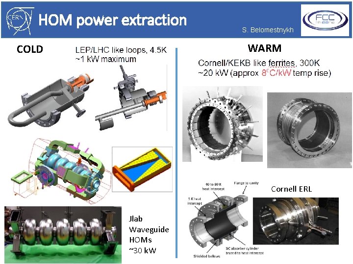
HOM power extraction S. Belomestnykh WARM COLD Waveguides Cornell ERL Jlab Waveguide HOMs ~30 k. W
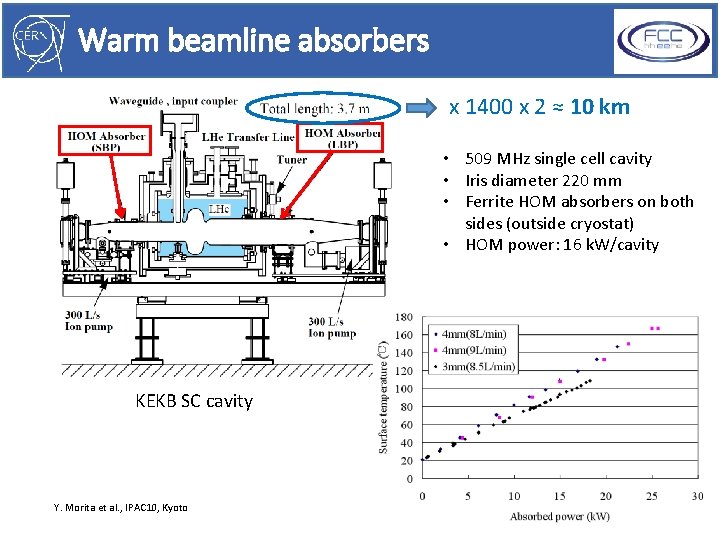
Warm beamline absorbers x 1400 x 2 ≈ 10 km • 509 MHz single cell cavity • Iris diameter 220 mm • Ferrite HOM absorbers on both sides (outside cryostat) • HOM power: 16 k. W/cavity KEKB SC cavity Y. Morita et al. , IPAC 10, Kyoto
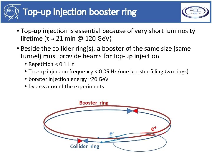
Top-up injection booster ring • Top-up injection is essential because of very short luminosity lifetime (τ ≈ 21 min @ 120 Ge. V) • Beside the collider ring(s), a booster of the same size (same tunnel) must provide beams for top-up injection • • Repetition < 0. 1 Hz Top-up injection frequency < 0. 05 Hz (one booster filling two rings) booster injection energy ~20 Ge. V bypass around the experiments
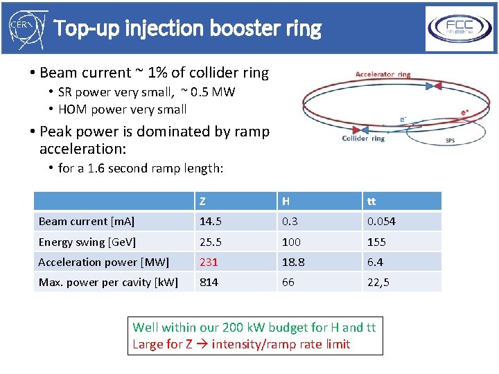
Top-up injection booster ring • Beam current ~ 1% of collider ring • SR power very small, ~ 0. 5 MW • HOM power very small • Peak power is dominated by ramp acceleration: • for a 1. 6 second ramp length: Z H tt Beam current [m. A] 14. 5 0. 3 0. 054 Energy swing [Ge. V] 25. 5 100 155 Acceleration power [MW] 231 18. 8 6. 4 Max. power per cavity [k. W] 814 66 22, 5 Well within our 200 k. W budget for H and tt Large for Z intensity/ramp rate limit

Conclusions • Iterations are ongoing on RF scenarios and staging, choice of cavities and cryomodule layout, RF frequency and cryogenic temperature. • The major challenges come from the requirements for both the highest possible accelerating voltage and very high beam currents with the same machine. • HOMs will be a major issue for running at the Z pole, and will dictate to a large extent the RF system design. • R&D on cavities with low loss factors and strong HOM damping • Design of compact warm absorber solution to avoid very long RF sections & minimize heat load due to cold/warm transitions • Variable Qext fundamental power couplers would seem to be desirable for energy efficiency • Strong RF feedback will be necessary for Z pole running to suppress coupled bunch modes driven by the fundamental cavity impedance
Thank you for your attention!
Spare slides
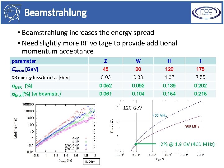
Beamstrahlung • Beamstrahlung increases the energy spread • Need slightly more RF voltage to provide additional momentum acceptance parameter Z W H t Ebeam [Ge. V] 45 80 120 175 SR energy loss/turn U 0 [Ge. V] 0. 03 0. 33 1. 67 7. 55 sd, SR [%] 0. 052 0. 092 0. 139 0. 202 sd, tot [%] (w beamstr. ) 0. 061 0. 104 0. 154 0. 215 120 Ge. V 400 MHz 800 MHz 2% @ 1. 9 GV (400 MHz) K. Ohmi
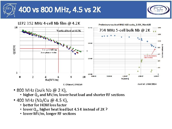
400 vs 800 MHz, 4. 5 vs 2 K LEP 2 352 MHz 4 -cell Nb film @ 4. 2 K 704 MHz 5 -cell bulk Nb @ 2 K E. Chiaveri, EPAC 96 • 800 MHz (bulk Nb @ 2 K), • higher Q 0 and MV/m, lower heat load and shorter RF sections • 400 MHz (Nb/Cu @ 4. 5 K), • better for HOM loss factor • lower Q 0, higher heat load but 4. 5 K instead of 2 K ? • lower MV/m, longer RF sections Xu et al. LINAC 2014
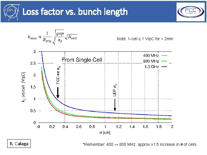
Loss factor vs. bunch length FCC-ee σz Note: 1 -cell ≥ 1 V/p. C for < 2 mm R. Calaga *Remember: 400 → 800 MHz: approx x 1. 5 increase in # of cells
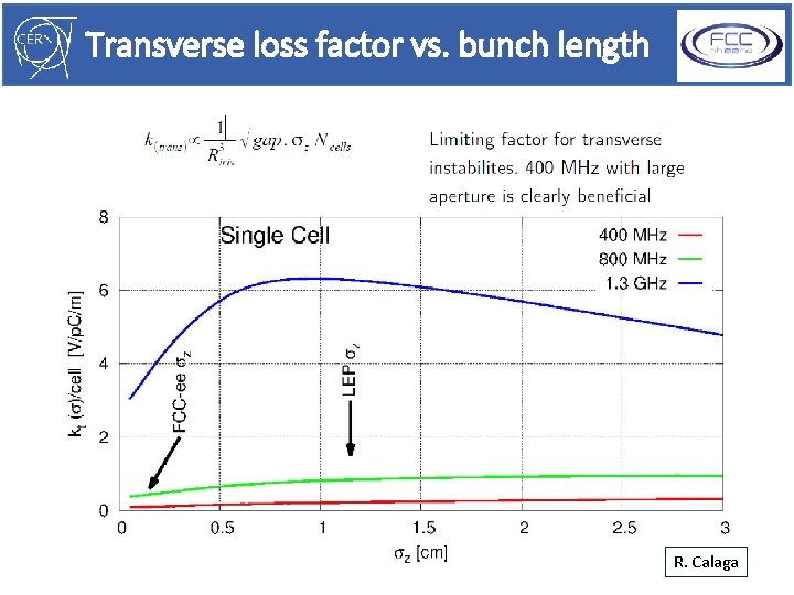
Transverse loss factor vs. bunch length R. Calaga

5 -cell SRF cavity with strong HOM damping for e. RHIC at BNL HOM high-pass filter HOM ports F = 703. 5 MHz Now scaled to 413 MHz HOM couplers: 6 of antenna-type Fundamental supression: two-stage high-pass filters Eacc = 20 MV/m Design HOM power: 7. 5 k. W FPC port § BNL 3 cavity optimized for high-current applications such as e. RHIC and SPL. § Three antenna-type HOM couplers attached to large diameter beam pipes at each end of the cavity provide strong damping § A two-stage high-pass filter rejects fundamental frequency, allows propagation of HOMs toward an RF load. M. Tigner, G. Hoffstaetter, SRF 2011, W. Xu et al, SRF 2011
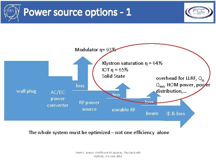
Power source options - 1 Modulator η≈ 93% wall plug loss AC/DC power converter Klystron saturation η ≈ 64% IOT η ≈ 65% Solid State overhead for LLRF, Qo, Qext, HOM power, power distribution, … loss RF power source loss useable RF beam Φ & loss The whole system must be optimized – not one efficiency alone From E. Jensen -En. Efficient RF Sources, The Cockcroft Institute, 3 -4 June 2014
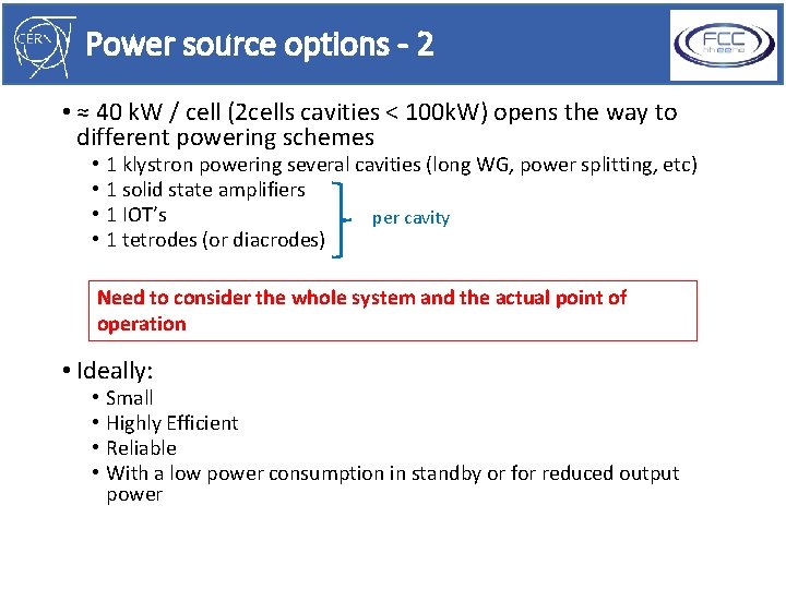
Power source options - 2 • ≈ 40 k. W / cell (2 cells cavities < 100 k. W) opens the way to different powering schemes • • 1 klystron powering several cavities (long WG, power splitting, etc) 1 solid state amplifiers 1 IOT’s per cavity 1 tetrodes (or diacrodes) Need to consider the whole system and the actual point of operation • Ideally: • • Small Highly Efficient Reliable With a low power consumption in standby or for reduced output power
- Slides: 32