
The Radiance Equation Mel Slater Outline l l
- Slides: 25
The Radiance Equation Mel Slater
Outline l l l l l Introduction Light Simplifying Assumptions Radiance Reflectance The Radiance Equation Traditional Rendering Solutions Visibility Conclusions
Introduction l Lighting is the central problem of real-time graphics rendering – Arbitrary shaped lights – Changes in lighting conditions – Real-time shadows – Real-time reflections – Mixtures of many different types of surface
Introduction l Real-time walkthrough with global illumination – Possible under limited conditions l Radiosity (diffuse surfaces only) l Real-time interaction – Not possible except for special case local illumination l Why is the problem so hard?
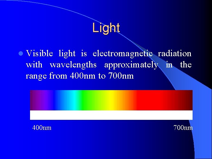
Light l Visible light is electromagnetic radiation with wavelengths approximately in the range from 400 nm to 700 nm 400 nm 700 nm
Light: Photons l Light can be viewed as wave or particle phenomenon l Particles are photons – packets of energy which travel in a straight line in vaccuum with velocity c (300, 000 m. p. s. ) l The problem of how light interacts with surfaces in a volume of space is an example of a transport problem.
Light: Radiant Power l denotes the radiant energy or flux in a volume V. l The flux is the rate of energy flowing through a surface per unit time (watts). l The energy is proportional to the particle flow, since each photon carries energy. l The flux may be thought of as the flow of photons per unit time.
Light: Flux Equilibrium l Total flux in a volume in dynamic equilibrium – Particles are flowing – Distribution is constant l Conservation of energy – Total energy input into the volume = total energy that is output by or absorbed by matter within the volume.
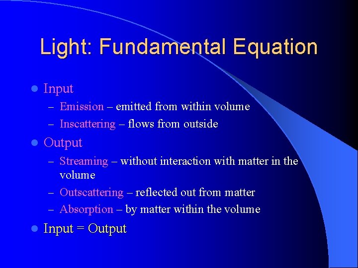
Light: Fundamental Equation l Input – Emission – emitted from within volume – Inscattering – flows from outside l Output – Streaming – without interaction with matter in the volume – Outscattering – reflected out from matter – Absorption – by matter within the volume l Input = Output
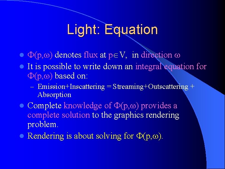
Light: Equation (p, ) denotes flux at p V, in direction l It is possible to write down an integral equation for (p, ) based on: l – Emission+Inscattering = Streaming+Outscattering + Absorption Complete knowledge of (p, ) provides a complete solution to the graphics rendering problem. l Rendering is about solving for (p, ). l
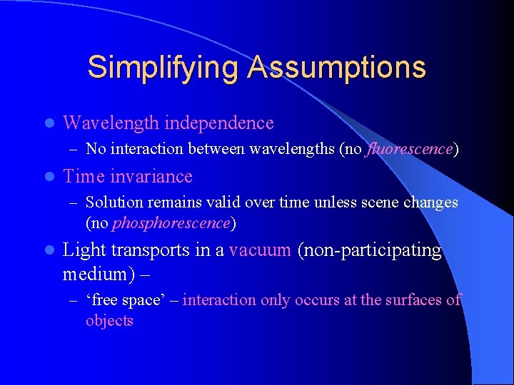
Simplifying Assumptions l Wavelength independence – No interaction between wavelengths (no fluorescence) l Time invariance – Solution remains valid over time unless scene changes (no phosphorescence) l Light transports in a vacuum (non-participating medium) – – ‘free space’ – interaction only occurs at the surfaces of objects
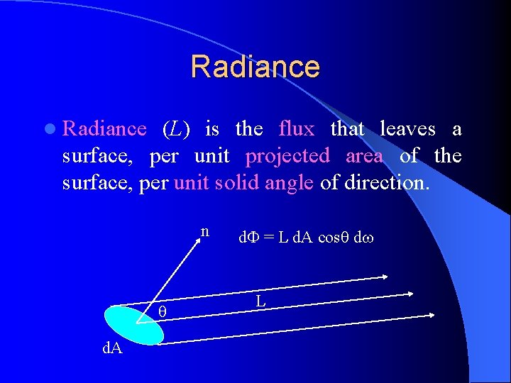
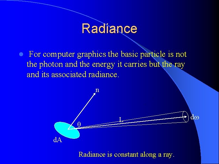
Radiance l Radiance (L) is the flux that leaves a surface, per unit projected area of the surface, per unit solid angle of direction. n d. A d = L d. A cos d L
Radiance l For computer graphics the basic particle is not the photon and the energy it carries but the ray and its associated radiance. n L d. A Radiance is constant along a ray. d
Radiance: Radiosity, Irradiance l Radiosity - is the flux per unit area that radiates from a surface, denoted by B. – d = B d. A l Irradiance is the flux per unit area that arrives at a surface, denoted by E. – d = E d. A
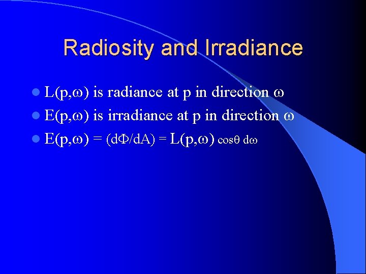
Radiosity and Irradiance is radiance at p in direction l E(p, ) is irradiance at p in direction l E(p, ) = (d /d. A) = L(p, ) cos d l L(p, )
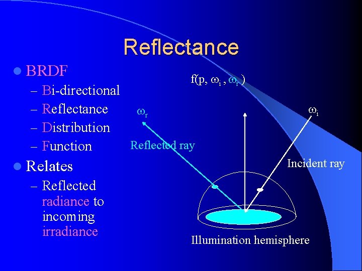
Reflectance l BRDF f(p, i , r ) – Bi-directional – Reflectance r – Distribution Reflected ray – Function l Relates – Reflected radiance to incoming irradiance i Incident ray Illumination hemisphere
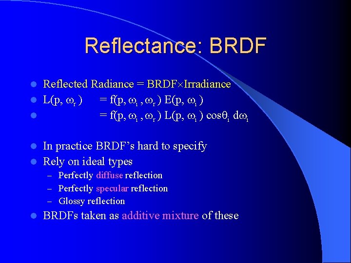
Reflectance: BRDF Reflected Radiance = BRDF Irradiance l L(p, r ) = f(p, i , r ) E(p, i ) l = f(p, i , r ) L(p, i ) cos i d i l In practice BRDF’s hard to specify l Rely on ideal types l – Perfectly diffuse reflection – Perfectly specular reflection – Glossy reflection l BRDFs taken as additive mixture of these
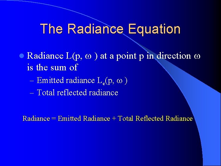
The Radiance Equation L(p, ) at a point p in direction is the sum of l Radiance – Emitted radiance Le(p, ) – Total reflected radiance Radiance = Emitted Radiance + Total Reflected Radiance
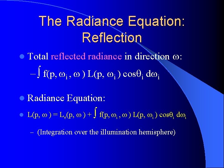
The Radiance Equation: Reflection l Total reflected radiance in direction : – f(p, i , ) L(p, i ) cos i d i l Radiance l Equation: L(p, ) = Le(p, ) + f(p, i , ) L(p, i ) cos i d i – (Integration over the illumination hemisphere)
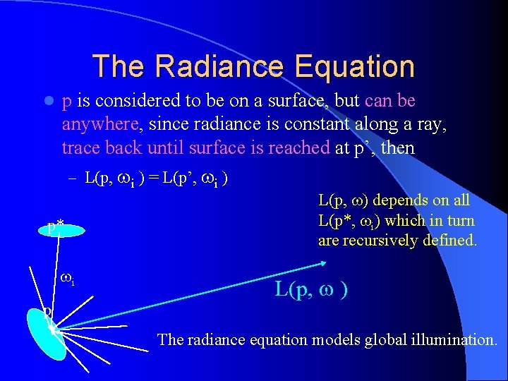
The Radiance Equation l p is considered to be on a surface, but can be anywhere, since radiance is constant along a ray, trace back until surface is reached at p’, then – L(p, i ) = L(p’, i ) p* i p L(p, ) depends on all L(p*, i) which in turn are recursively defined. L(p, ) The radiance equation models global illumination.
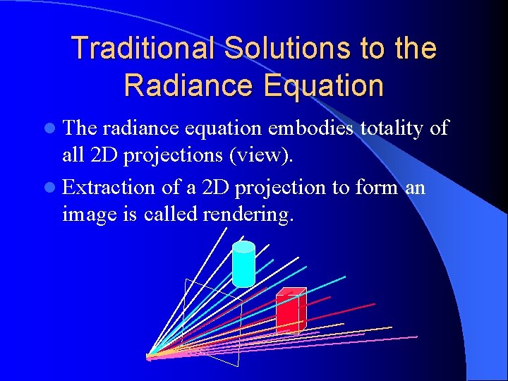
Traditional Solutions to the Radiance Equation l The radiance equation embodies totality of all 2 D projections (view). l Extraction of a 2 D projection to form an image is called rendering.
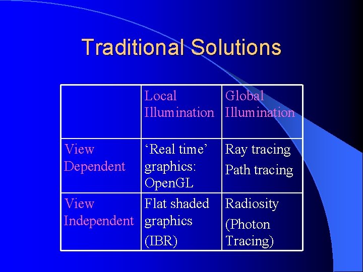
Traditional Solutions Local Global Illumination View Dependent ‘Real time’ graphics: Open. GL View Flat shaded Independent graphics (IBR) Ray tracing Path tracing Radiosity (Photon Tracing)
(Image Based Rendering) l IBR not a ‘traditional’ solution l Images for a new view constructed from a large collection of existing images l No lighting computations at all. l Light Field Rendering specific instance to be discussed later.
Visibililty l Where does an incident ray through the image plane come from? – Which surface? Ray tracing in principle has to search all surfaces for possible intersections l Radiosity has to include visibility in form-factor calculations between surfaces l Real-time rendering solves visibility problem on a pixel by pixel basis (z-buffer). l – Major complication for large scenes l We will see later that LFR does not have this visibility problem.
Conclusions Graphics rendering is concerned with solution of integral radiance equation l Traditional solutions are various kinds of approximations to this equation. l Rendering is the process of extracting images from the equation. l Rendering may be view dependent or independent, together with a global or local illumination solution. l