
The Prototype Correlator Sonja Vrcic 2006 12 05

- Slides: 28
The Prototype Correlator Sonja Vrcic, 2006 -12 -05 EVLA M&C Transition System Software Socorro, - CDR 5. December, 2006
Introduction • Testing with the prototype correlator will be preformed in three phases: 1. Hardware testing 2. Software testing 3. Scientific Tests • • The Phase I is well-defined. 34 tests are listed in the Brent’s test plan. Software requirements for the Phase I are well defined (with possible exception of the Backend software). 10 science driven tests for Phase I to be defined. Phase 2 includes testing of : – – – • MCCC & VCI software, EVLA Monitor & Control Software (Executor and beyond) Correlator Backend software, Data Capture, Data Analysis, etc. Phase 2 and 3 will overlap, as software is being developed. Sonja Vrcic, 2006 -12 -05 EVLA M&C Transition System Software - CDR 2
Outline 1. Configuration for the on-the-sky testing in Socorro - hardware verification. The purpose of the on-the-sky testing with the prototype correlator is to establish, before the full production, that the hardware functions properly. 2. Prototype correlator - configuration. 3. NRAO inputs required for on-the-sky testing. 4. Software to be provided by the correlator team for the on-the-sky testing. Sonja Vrcic, 2006 -12 -05 EVLA M&C Transition System Software - CDR 3
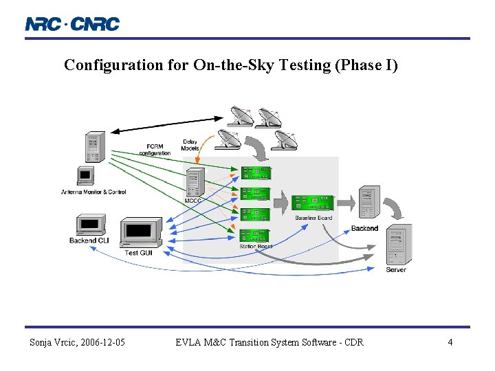
Configuration for On-the-Sky Testing (Phase I) Sonja Vrcic, 2006 -12 -05 EVLA M&C Transition System Software - CDR 4
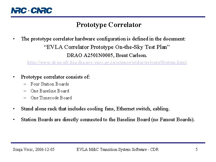
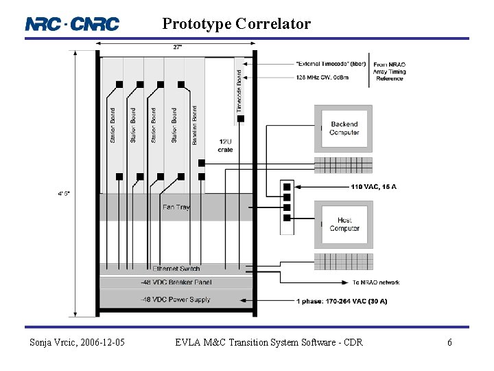
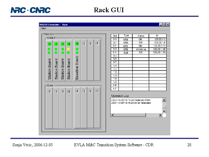
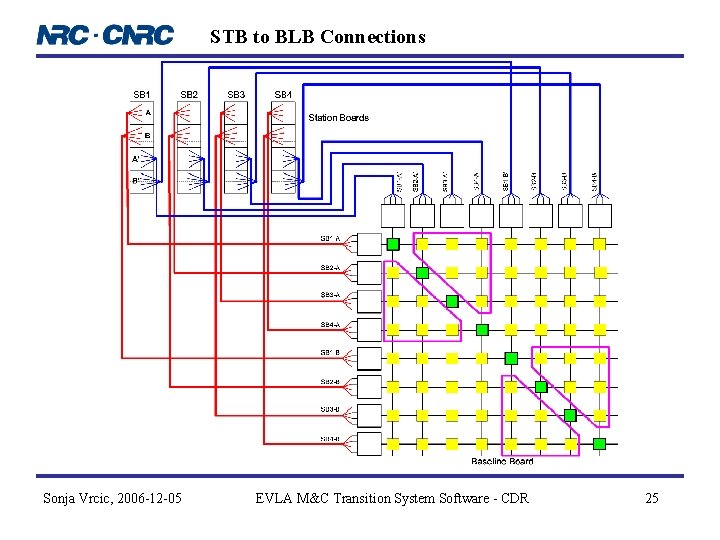
Prototype Correlator • The prototype correlator hardware configuration is defined in the document: “EVLA Correlator Prototype On-the-Sky Test Plan” DRAO A 2501 N 0005, Brent Carlson. http: //www. drao-ofr. hia-iha. nrc-cnrc. gc. ca/science/widar/private/System. html • Prototype correlator consists of: – Four Station Boards – One Baseline Board – One Timecode Board • Stand alone rack that includes cooling fans, Ethernet switch, cabling. • Station Boards are directly connected to the Baseline Board (no Fanout Boards). Sonja Vrcic, 2006 -12 -05 EVLA M&C Transition System Software - CDR 5
Prototype Correlator Sonja Vrcic, 2006 -12 -05 EVLA M&C Transition System Software - CDR 6
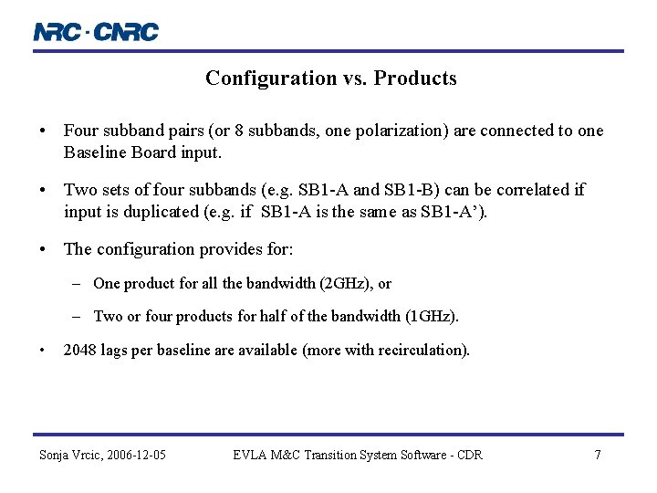
Configuration vs. Products • Four subband pairs (or 8 subbands, one polarization) are connected to one Baseline Board input. • Two sets of four subbands (e. g. SB 1 -A and SB 1 -B) can be correlated if input is duplicated (e. g. if SB 1 -A is the same as SB 1 -A’). • The configuration provides for: – One product for all the bandwidth (2 GHz), or – Two or four products for half of the bandwidth (1 GHz). • 2048 lags per baseline are available (more with recirculation). Sonja Vrcic, 2006 -12 -05 EVLA M&C Transition System Software - CDR 7
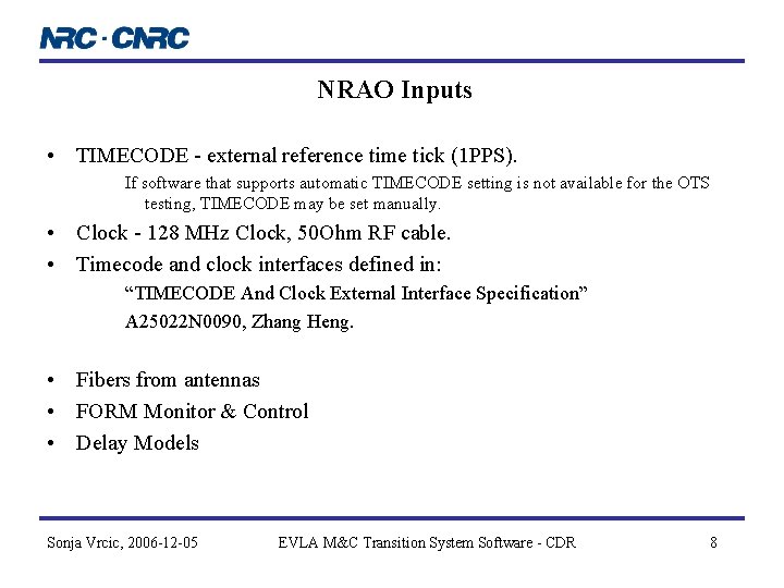
NRAO Inputs • TIMECODE - external reference time tick (1 PPS). If software that supports automatic TIMECODE setting is not available for the OTS testing, TIMECODE may be set manually. • Clock - 128 MHz Clock, 50 Ohm RF cable. • Timecode and clock interfaces defined in: “TIMECODE And Clock External Interface Specification” A 25022 N 0090, Zhang Heng. • Fibers from antennas • FORM Monitor & Control • Delay Models Sonja Vrcic, 2006 -12 -05 EVLA M&C Transition System Software - CDR 8
Fiber Optic Receiver Module - FORM • Fibers from antennas will be connected to FORMs (mezzanine cards) installed on the Station Boards. • A basic Monitor and Control interface should be provided that enables user to: – – reset the board, set IP address, obtain information regarding h/w and s/w version, obtain information regarding board status and configuration. • Ability to send FORM output, via coaxial cables, to (old) VLA correlator is necessary for comparison tests. H/w and s/w needed for these connections should be available for the OTS testing. Sonja Vrcic, 2006 -12 -05 EVLA M&C Transition System Software - CDR 9
Delay Models • Model Server is a task, somewhere in the NRAO network, that generates polynomial delay models for antennas involved in the testing. • Model Server will be a part of the Antenna Monitor & Control software. • Baseline requirements for the delay models are specified in the Programmer’s Guide A 25290 N 0000. • Order of the polynomial is a free parameter, specified in the model. • During the testing, models are transmitted as XML documents. • Format (XML Schema) is defined and posted on the DRAO web page. • When the full system is installed, if the performance and/or amount of network traffic becomes a concern, the verbose format, used during the testing, can be replaced with more compact and easier to parse. Sonja Vrcic, 2006 -12 -05 EVLA M&C Transition System Software - CDR 10
Correlator Software Correlator team will provide the following: – Station Board CMIB software – Baseline Board CMIB software – Correlator Backend software – A single point of access for Delay Models (MCCC/VCI) – GUI based test tools that provide Monitor and Control functionality – Real-Time Data Display – Utility routines to generate Station Board filter coefficients, test vectors, analyze output data, etc. Sonja Vrcic, 2006 -12 -05 EVLA M&C Transition System Software - CDR 11
CMIB Software – Station Board and Baseline Board CMIB software including drivers and Module Access Handlers for FPGAs and ASIC. – Station Board real-time software including: • wide band delay tracking • phase model generation • real-time dump control generation for: – normal dumping, – recirculation and – phase binning. – Station Board and Baseline Board software able to accept and activate low-level configuration specified for each device (FPGA or ASIC) individually. Sonja Vrcic, 2006 -12 -05 EVLA M&C Transition System Software - CDR 12
Correlator Backend (CBE) • Correlator Backend software must be able: – to save data sets in the format used by the Real-Time Data Display and other tools. – to perform integration (data reduction) as specified in the configuration. • Basic Monitor & Control functionality that enables user: – To specify integration factor and destination for the output data, and – To monitor CBE status. • CBE should be able to accept configuration formatted as XML document so that the CBE configuration can be integrated into the Observation Builder and Test Executor. • Multi-node functionality is not necessary for the OTS testing. • The format for the CBE output is to be defined. • The detailed list of requirements and priorities for the CBE is still to be defined. Sonja Vrcic, 2006 -12 -05 EVLA M&C Transition System Software - CDR 13
Master Correlator Control Computer (MCCC) Virtual Correlator Interface (VCI) • At the time of on-the-sky testing (Phase I) correlator configuration and monitoring is performed using GUI based tools developed for the testing. • A basic MCCC software is required to handle Delay Models. • Connections between antennas and the Station Boards are managed by the EVLA Monitor and Control System (EMCS); the correlator expects to receive Delay Models with the Station Board Identifier (rack/crate/slot ID) specified for each baseband. • EMCS is not aware of the Station Board IP addresses. Translation of the Board ID (rack/crate/slot) to IP address is performed by MCCC. • During the testing, Delay Models are transmitted as human readable (i. e. rather verbose) XML messages. Sonja Vrcic, 2006 -12 -05 EVLA M&C Transition System Software - CDR 14
GUI Based Tools • During the initial on-the-sky testing, higher layers of Station Board, Baseline Board and MCCC software will not be available. • A set of GUI based tools will be used to monitor and control the prototype correlator. • Optimization will be provided where possible, but, in general, user will have to create configuration for each FPGA / ASIC. • User should be able to build, save, recall and execute configurations. • User should be able to group configurations for a specific device (e. g. Station Board, Backend), and for a specific test (observation), and to recall a complete set when needed. Sonja Vrcic, 2006 -12 -05 EVLA M&C Transition System Software - CDR 15
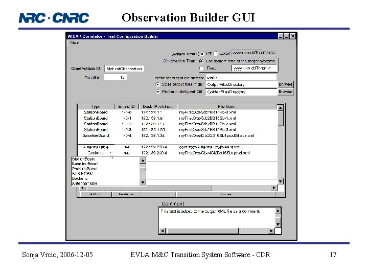
Observation Builder • Observation Builder is a tool that allows user to specify a list of devices and subsystems that belong to the same observation. • A configuration file can be specified for each device or subsystem. • A limited set of “observation parameters” are common to all the subsystems that belong to the same observation (e. g. observation ID and activation time). • Observation Builder allows user to open existing observation configuration file, modify the configuration and save it, either in the same or in a new file. • Board-level and chip-level GUIs are provided for the Station Board and Baseline Board. • Board-level GUIs allow user to specify configuration for each FPGA / ASIC and to specify a group of chip-level configurations as a “board configuration”. Sonja Vrcic, 2006 -12 -05 EVLA M&C Transition System Software - CDR 16
Observation Builder GUI Sonja Vrcic, 2006 -12 -05 EVLA M&C Transition System Software - CDR 17
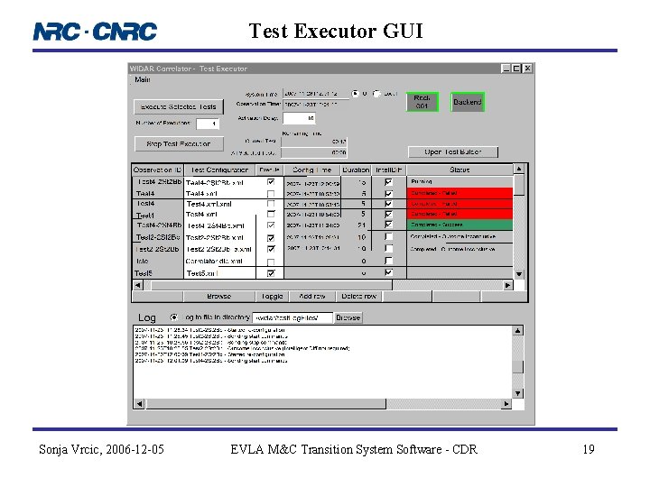
Test Executor • Test Executor is a GUI based tool that provides hierarchical view of the correlator to enable user to set configuration and determine the status in intuitive way. • Test Executor enables user to select a list of the previously created observation configurations and execute them either immediately or at the specified time. • Based on the logs/alarms and queries Test Executor monitors the state of the correlator subsystems. Sonja Vrcic, 2006 -12 -05 EVLA M&C Transition System Software - CDR 18
Test Executor GUI Sonja Vrcic, 2006 -12 -05 EVLA M&C Transition System Software - CDR 19
Rack GUI Sonja Vrcic, 2006 -12 -05 EVLA M&C Transition System Software - CDR 20
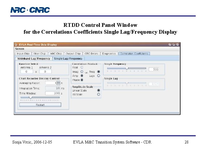
Real-Time Data Display (RTDD) • RTDD is a platform independent graphical user interface that provides visualization of the correlator output products (Station Board output and CBE output). • Self-contained software package. • Development platform: Java, Java Swing and Java 2 D Graph Package. • Data can be displayed (plotted) in real-time or from the previously created files. • User will be able to view graphs in “slow motion”. • Histogram display modes: overwrite vs. persistence mode. Sonja Vrcic, 2006 -12 -05 EVLA M&C Transition System Software - CDR 21
Status • Basic CMIB software including operating system and communication software is ready for testing. • Drivers and Module Access Handlers for the Baseline Board and Station Board are ready for testing. • Testing of the Baseline Board software has started: – FPGAs have been successfully programmed. – Read/write access to registers has been tested. • GUIs for the Station Board and Baseline Board FPGAs and ASIC are ready for testing. • Higher-level GUIs (Test Executor, Test Builder etc. ) have been defined. • Basic CBE functionality have been implemented. Software is installed in DRAO lab. • Routines that performatting of the raw binary output of the CBE into ASCII files have been developed. • RTDD for the Station Board products is under development. • A number of utility routines that generate Station Board filter coefficients, test vectors, direct access to FPFA registers, etc. have been developed and are already being used. Sonja Vrcic, 2006 -12 -05 EVLA M&C Transition System Software - CDR 22
The End Sonja Vrcic, 2006 -12 -05 EVLA M&C Transition System Software - CDR 23
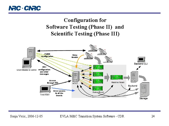
Configuration for Software Testing (Phase II) and Scientific Testing (Phase III) Sonja Vrcic, 2006 -12 -05 EVLA M&C Transition System Software - CDR 24
STB to BLB Connections Sonja Vrcic, 2006 -12 -05 EVLA M&C Transition System Software - CDR 25
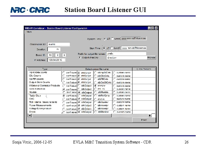
Station Board Listener GUI Sonja Vrcic, 2006 -12 -05 EVLA M&C Transition System Software - CDR 26
RTDD Control Panel Window Station Board Filter Sonja Vrcic, 2006 -12 -05 EVLA M&C Transition System Software - CDR 27
RTDD Control Panel Window for the Correlations Coefficients Single Lag/Frequency Display Sonja Vrcic, 2006 -12 -05 EVLA M&C Transition System Software - CDR 28