
The Preliminary Results of Laser Time Transfer LTT


- Slides: 34
The Preliminary Results of Laser Time Transfer (LTT) Experiment Yang Fumin(1), Huang Peicheng(1), Ivan Prochazka(2), Zhang Zhongping(1), Chen Wanzhen(1), Zhang Haifeng(1), Wang Yuanming(1), Meng Wendong(1), Wang Jie(3), Liao Yin(3), Zou Guangnan(3), Wang Luyuan(3), Zhao You(4), Fan Cunbo(4) and Han Xingwei(4) (1) Shanghai Observatory, Chinese Academy of Sciences, Shanghai, China (2) Czech Technical University in Prague, Czech Republic (3) China Academy of Space and Technology, Beijing, China (4) Changchun Observatory, Chinese Academy of Sciences, Changchun, China yangfm@shao. ac. cn
Goals • Evaluate the performance of the space rubidium clocks with respective to the ground hydrogen maser, dedicated for the Compass system • Testing of the Relativity theory
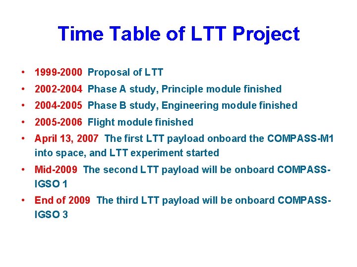
Time Table of LTT Project • 1999 -2000 Proposal of LTT • 2002 -2004 Phase A study, Principle module finished • 2004 -2005 Phase B study, Engineering module finished • 2005 -2006 Flight module finished • April 13, 2007 The first LTT payload onboard the COMPASS-M 1 into space, and LTT experiment started • Mid-2009 The second LTT payload will be onboard COMPASS- IGSO 1 • End of 2009 The third LTT payload will be onboard COMPASSIGSO 3
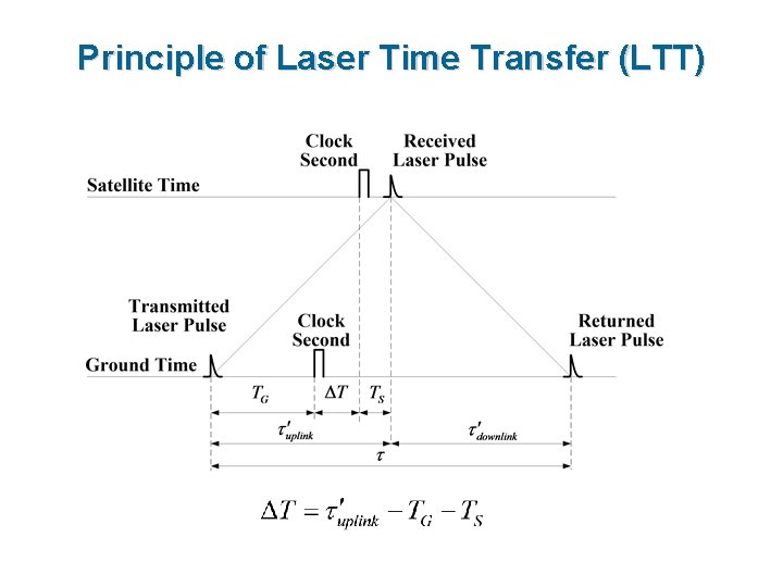
Principle of Laser Time Transfer (LTT)
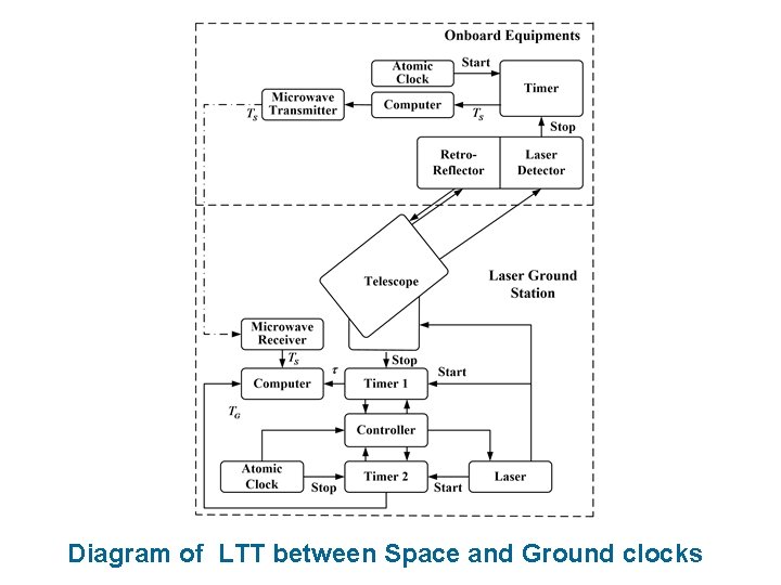
Diagram of LTT between Space and Ground clocks
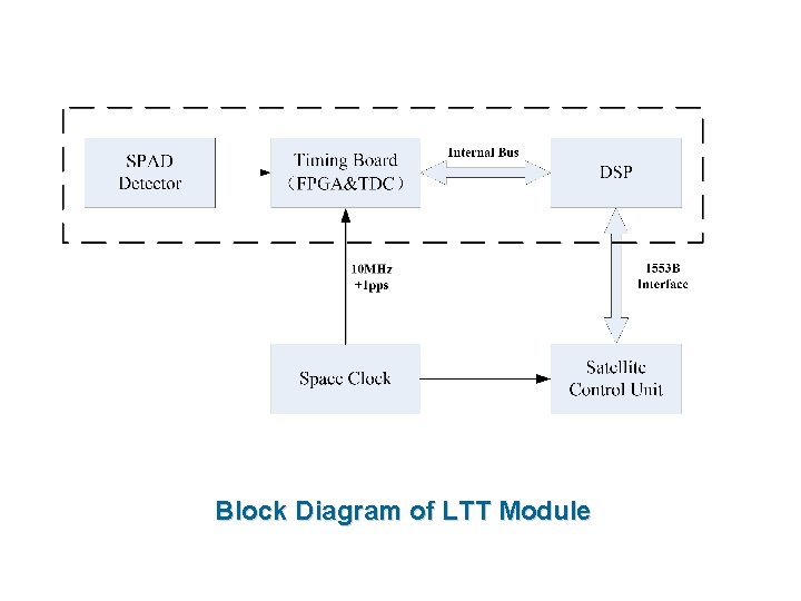
Block Diagram of LTT Module
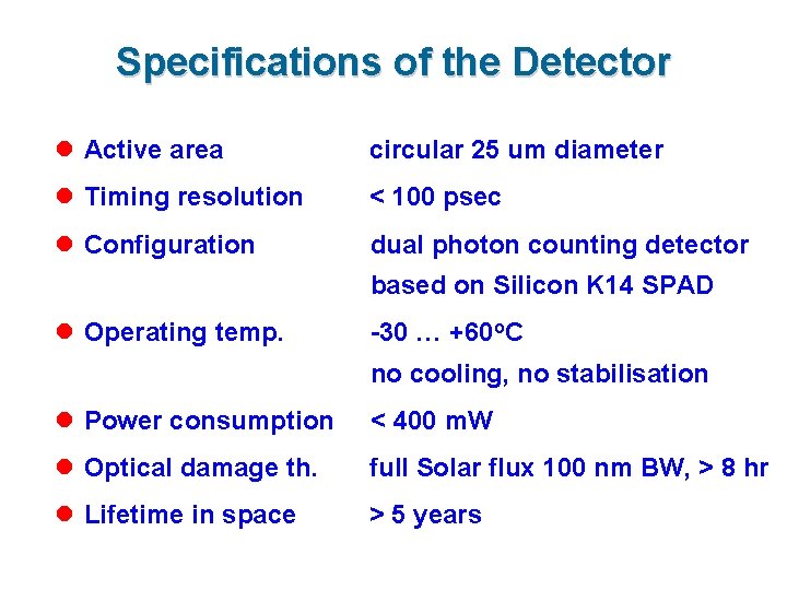
Specifications of the Detector l Active area circular 25 um diameter l Timing resolution < 100 psec l Configuration dual photon counting detector based on Silicon K 14 SPAD l Operating temp. -30 … +60 o. C no cooling, no stabilisation l Power consumption < 400 m. W l Optical damage th. full Solar flux 100 nm BW, > 8 hr l Lifetime in space > 5 years
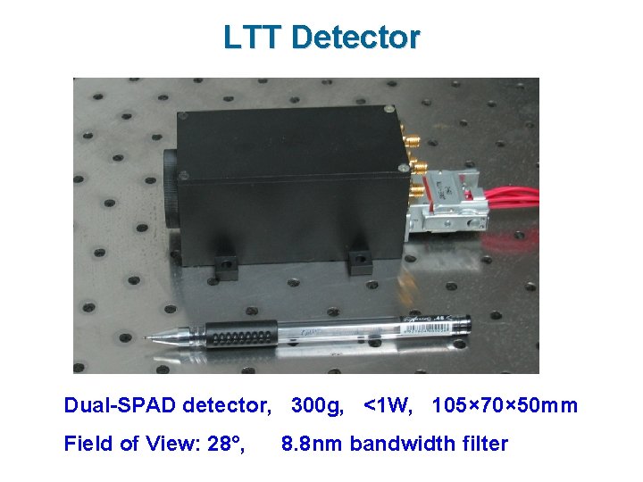
LTT Detector Dual-SPAD detector, 300 g, <1 W, 105× 70× 50 mm Field of View: 28°, 8. 8 nm bandwidth filter
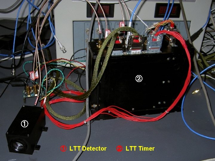
② ① ① LTT Detector ② LTT Timer
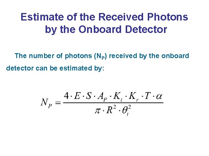
Estimate of the Received Photons by the Onboard Detector The number of photons (NP) received by the onboard detector can be estimated by:
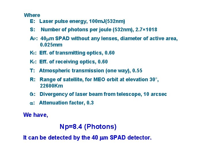
Where E: Laser pulse energy, 100 m. J(532 nm) S: Number of photons per joule (532 nm), 2. 7× 10¹⁸ AP: 40 m SPAD without any lenses, diameter of active area, 0. 025 mm Kt: Eff. of transmitting optics, 0. 60 Kr: Eff. of receiving optics, 0. 60 T: Atmospheric transmission (one way), 0. 55 R: Range of satellite, for MEO orbit at elevation 30°, 22600 Km t: Divergency of laser beam from telescope, 10 arcsec : Attenuation factor, 0. 3 We have, Np=8. 4 (Photons) It can be detected by the 40 m SPAD detector.
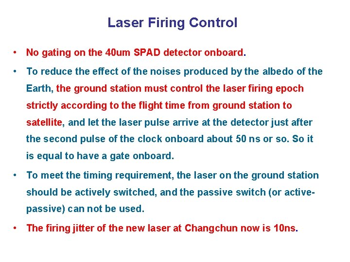
Laser Firing Control • No gating on the 40 um SPAD detector onboard. • To reduce the effect of the noises produced by the albedo of the Earth, the ground station must control the laser firing epoch strictly according to the flight time from ground station to satellite, and let the laser pulse arrive at the detector just after the second pulse of the clock onboard about 50 ns or so. So it is equal to have a gate onboard. • To meet the timing requirement, the laser on the ground station should be actively switched, and the passive switch (or activepassive) can not be used. • The firing jitter of the new laser at Changchun now is 10 ns.
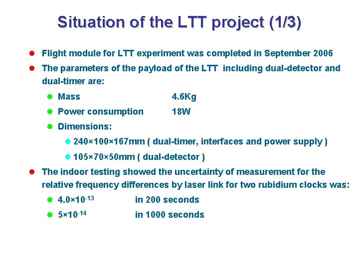
Situation of the LTT project (1/3) l Flight module for LTT experiment was completed in September 2006 l The parameters of the payload of the LTT including dual-detector and dual-timer are: l Mass 4. 6 Kg l Power consumption 18 W l Dimensions: l 240× 100× 167 mm ( dual-timer, interfaces and power supply ) l 105× 70× 50 mm ( dual-detector ) l The indoor testing showed the uncertainty of measurement for the relative frequency differences by laser link for two rubidium clocks was: l 4. 0× 10 -13 in 200 seconds l 5× 10 -14 in 1000 seconds
Situation of the LTT project (2/3) l The LTT payload onboard the Chinese experimental navigation satellite <Compass-M 1> was launched on April 13, 2007. The orbital altitude of Compass-M 1 is 21500 km. l The LTT experiment between the ground and the LTT payload has been done at the Changchun SLR station since August 2007.
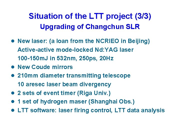
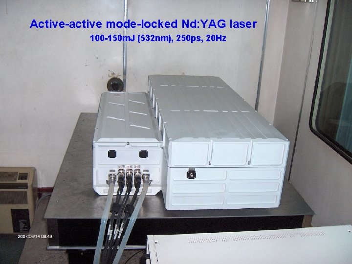
Situation of the LTT project (3/3) Upgrading of Changchun SLR l New laser: (a loan from the NCRIEO in Beijing) Active-active mode-locked Nd: YAG laser 100 -150 m. J in 532 nm, 250 ps, 20 Hz l New Coude mirrors l 210 mm diameter transmitting telescope 10 aresec laser beam divergency l 2 sets of event timer (Riga Univ. ) l 1 set of hydrogen maser (Shanghai Obs. ) l LTT software: laser firing control, LTT data analysis
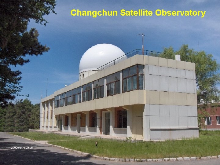
Changchun Satellite Observatory
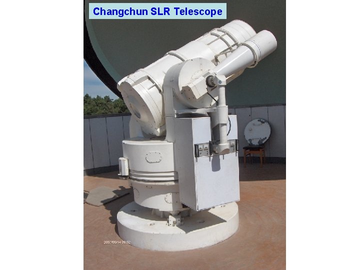
Changchun SLR Telescope
Active-active mode-locked Nd: YAG laser 100 -150 m. J (532 nm), 250 ps, 20 Hz
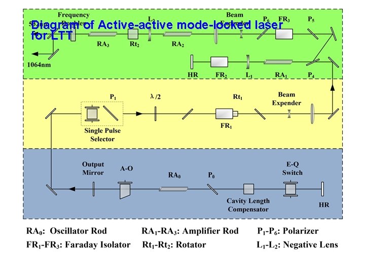
Diagram of Active-active mode-locked laser for LTT
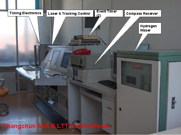
Timing Electronics Laser & Tracking Control Event Timer (2) Compass Receiver Hydrogen Maser Changchun SLR & LTT Control Room
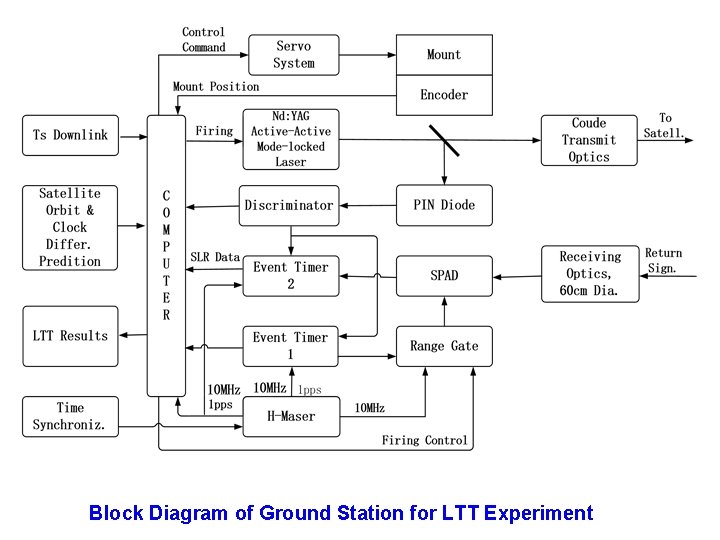
Block Diagram of Ground Station for LTT Experiment
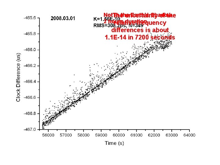
Some results of LTT experiment on clock differences between space and ground clocks
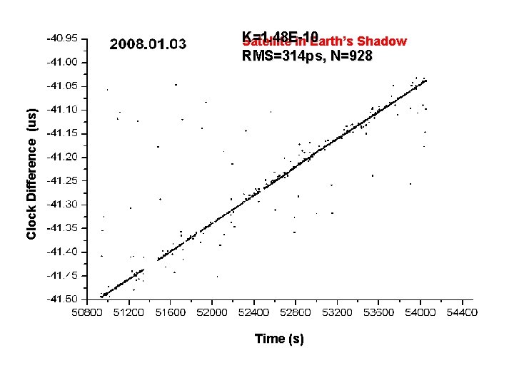
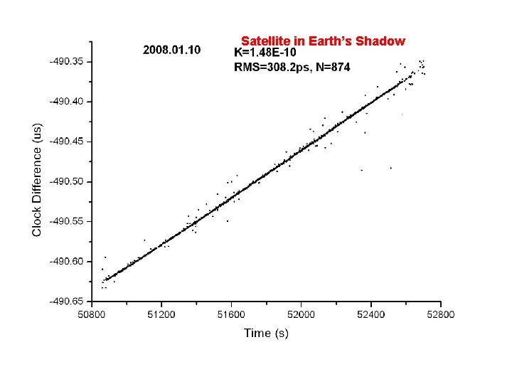
Clock Difference (us) K=1. 48 E-10 Satellite in Earth’s Shadow RMS=314 ps, N=928 Time (s)
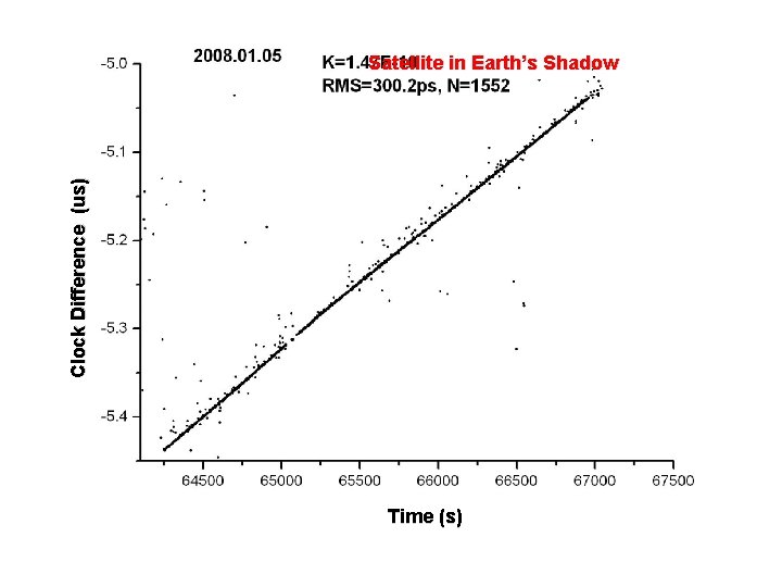
Clock Difference (us) Satellite in Earth’s Shadow Time (s)
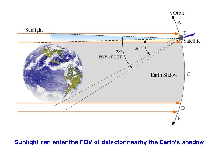
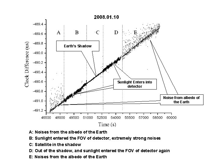
Sunlight can enter the FOV of detector nearby the Earth’s shadow
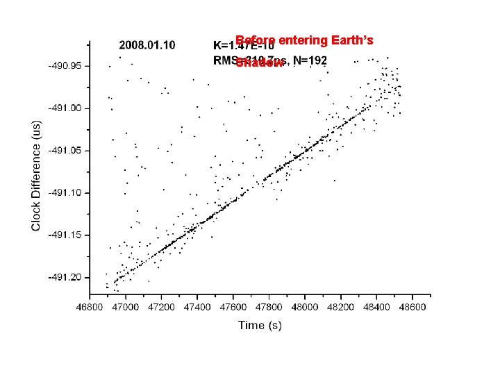
Earth’s Shadow Sunlight Enters into detector Noise from albedo of the Earth A: Noises from the albedo of the Earth B: Sunlight entered the FOV of detector, extremely strong noises C: Satellite in the shadow D: Out of the shadow, and sunlight entered the FOV of detector again E: Noises from the albedo of the Earth
Before entering Earth’s Shadow
Satellite in Earth’s Shadow
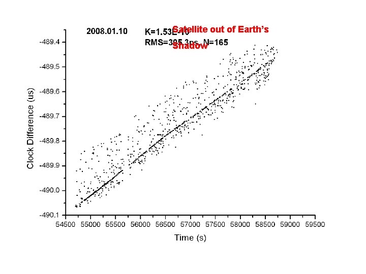
Satellite out of Earth’s Shadow
Not in the Earth’s Shadow The uncertainty of the 2 hours duration relative frequency differences is about 1. 1 E-14 in 7200 seconds
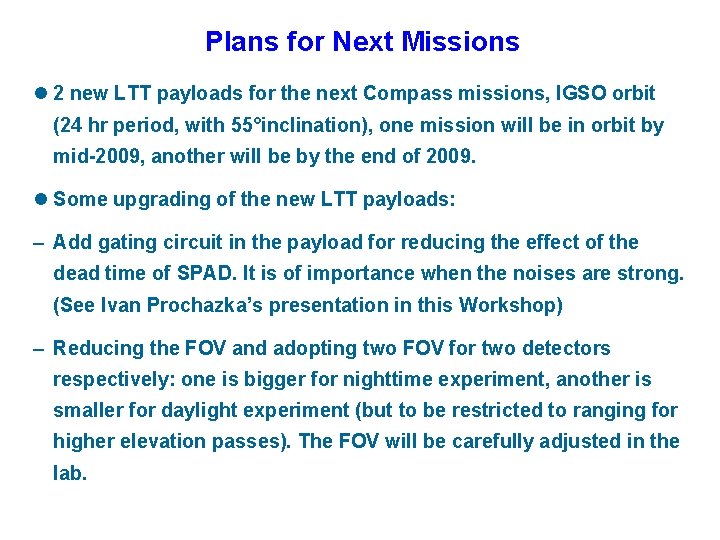
Plans for Next Missions l 2 new LTT payloads for the next Compass missions, IGSO orbit (24 hr period, with 55°inclination), one mission will be in orbit by mid-2009, another will be by the end of 2009. l Some upgrading of the new LTT payloads: – Add gating circuit in the payload for reducing the effect of the dead time of SPAD. It is of importance when the noises are strong. (See Ivan Prochazka’s presentation in this Workshop) – Reducing the FOV and adopting two FOV for two detectors respectively: one is bigger for nighttime experiment, another is smaller for daylight experiment (but to be restricted to ranging for higher elevation passes). The FOV will be carefully adjusted in the lab.
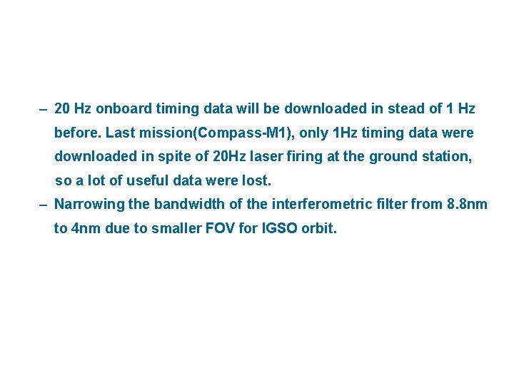
– 20 Hz onboard timing data will be downloaded in stead of 1 Hz before. Last mission(Compass-M 1), only 1 Hz timing data were downloaded in spite of 20 Hz laser firing at the ground station, so a lot of useful data were lost. – Narrowing the bandwidth of the interferometric filter from 8. 8 nm to 4 nm due to smaller FOV for IGSO orbit.
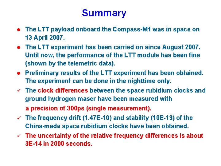
Summary l The LTT payload onboard the Compass-M 1 was in space on 13 April 2007. l The LTT experiment has been carried on since August 2007. Until now, the performance of the LTT module has been fine (shown by the telemetric data). l Preliminary results of the LTT experiment has been obtained. The experiment can be done in the nighttime only. ü The clock differences between the space rubidium clocks and ground hydrogen maser have been measured with a precision of 300 ps (single measurement). ü The frequency drift (1. 47 E-10) and stability (10 E-13) of the China-made space rubidium clocks have been obtained. ü The uncertainty of the relative frequency differences is about 3 E-14 in 2000 seconds.
Thank you