
The polarization RSE tabletop interferometer Peter Beyersdorf Seiji
The polarization RSE tabletop interferometer Peter Beyersdorf, Seiji Kawamura, Fumiko Kawazoe, Kentaro Somiya National Astronomical Observatory of Japan Marcel Aguerros University of Washington LIGOBeyersdorf. G 040047 -00 -Z DCC# G 040047 -00 -Z Peter
Polarization RSE is a frequency tunable (RSE) interferometer configuration that uses the control and readout schemes of first generation (non-RSE) detectors. n n Why is this important? How does it work? Results from the prototype Conclusion Peter Beyersdorf G 040047 -00 -Z 3
Motivation n Resonant Sideband Extraction (RSE) will be used in second generation detectors q q q n Control schemes and signal readout used with 1 st generation detectors are inadequate for conventional RSE configurations. q q n Reduces thermal load on the beamsplitter Allows frequency tuning of the interferometer Can beat the standard quantum limit at certain frequencies More cross-coupling of length degrees of freedom in RSE configurations Modified control schemes use extra RF sidebands which greatly increase detector bandwidth requirements Imbalance of RF sidebands in detuned configurations make RF readout susceptible to excess technical noise (although may allow reduction in quantum noise) detuning requires reoptimizing demodulation phases Goal: create and demonstrate a frequency tunable (RSE) configuration compatible with the readout and control schemes of first generation detectors. Peter Beyersdorf G 040047 -00 -Z 4
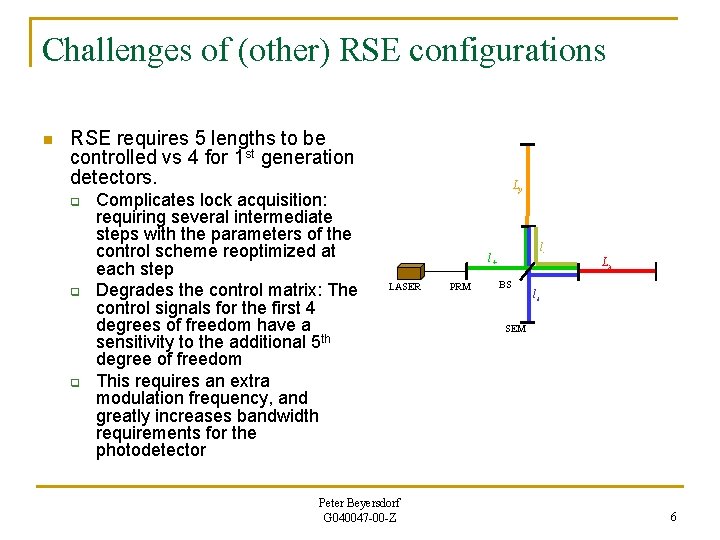
Challenges of (other) RSE configurations n RSE requires 5 lengths to be controlled vs 4 for 1 st generation detectors. q q q Complicates lock acquisition: requiring several intermediate steps with the parameters of the control scheme reoptimized at each step Degrades the control matrix: The control signals for the first 4 degrees of freedom have a sensitivity to the additional 5 th degree of freedom This requires an extra modulation frequency, and greatly increases bandwidth requirements for the photodetector Ly l- l+ LASER Peter Beyersdorf G 040047 -00 -Z PRM BS Lx ls SEM 6
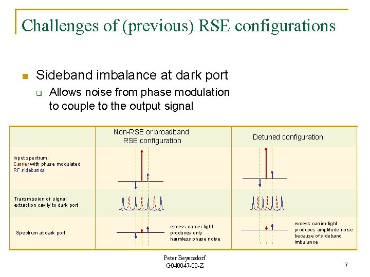
Challenges of (previous) RSE configurations n Sideband imbalance at dark port q Allows noise from phase modulation to couple to the output signal Non-RSE or broadband RSE configuration Detuned configuration Input spectrum: Carrier with phase modulated RF sidebands Transmission of signal extraction cavity to dark port Spectrum at dark port: excess carrier light produces only harmless phase noise Peter Beyersdorf G 040047 -00 -Z excess carrier light produces amplitude noise because of sideband imbalance 7
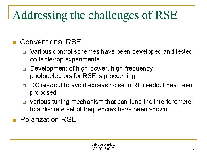
Addressing the challenges of RSE n Conventional RSE q q n Various control schemes have been developed and tested on table-top experiments Development of high-power, high-frequency photodetectors for RSE is proceeding DC readout to avoid excess noise in RF readout has been proposed various tuning mechanism that can tune the interferometer to a discrete set of frequencies have been shown Polarization RSE Peter Beyersdorf G 040047 -00 -Z 8
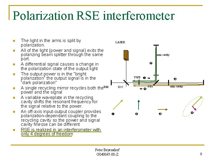
Polarization RSE interferometer n n n n The light in the arms is split by polarization. All of the light (power and signal) exits the polarizing beam splitter through the same port. A differential signal causes a change in the polarization state of the output light The output power is in the “bright polarization” the output signal is in the “dark polarization” A single recycling mirror recycles both the. RM power and the signal A variable waveplate in the recycling cavity shifts the resonant frequency for the signal relative to the power. An off-axis input-output coupler provides polarization-dependant coupling to the recycling cavity so the power and signal cavity finesse can be different RSE is realized in an interferometer with only 4 degrees of freedom LASER arm cavity ➋ VWP ➊ IOC ➊ Peter Beyersdorf G 040047 -00 -Z ➍ ➋ ➌ arm cavity PBS ➌ ➍ 9
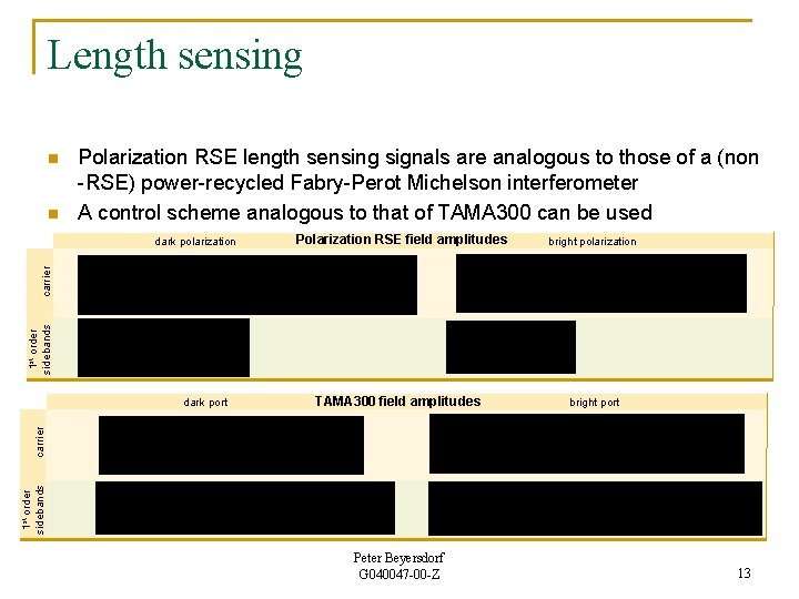
Length sensing n n Polarization RSE length sensing signals are analogous to those of a (non -RSE) power-recycled Fabry-Perot Michelson interferometer A control scheme analogous to that of TAMA 300 can be used Polarization RSE field amplitudes bright polarization 1 st order sidebands carrier dark polarization TAMA 300 field amplitudes bright port 1 st order sidebands carrier dark port Peter Beyersdorf G 040047 -00 -Z 13
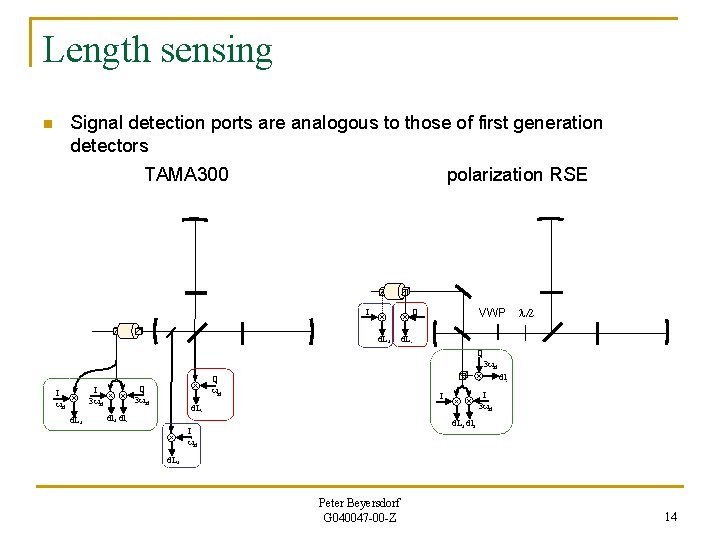
Length sensing Signal detection ports are analogous to those of first generation detectors n TAMA 300 polarization RSE I VWP Q d. L+ d. LQ I 3 wrf I wrf d. L+ I 3 wrf I d. L- dl+ dl- 3 wrf dl- Q wrf Q 3 wrf l/2 d. L+ dl+ I wrf d. L+ Peter Beyersdorf G 040047 -00 -Z 14
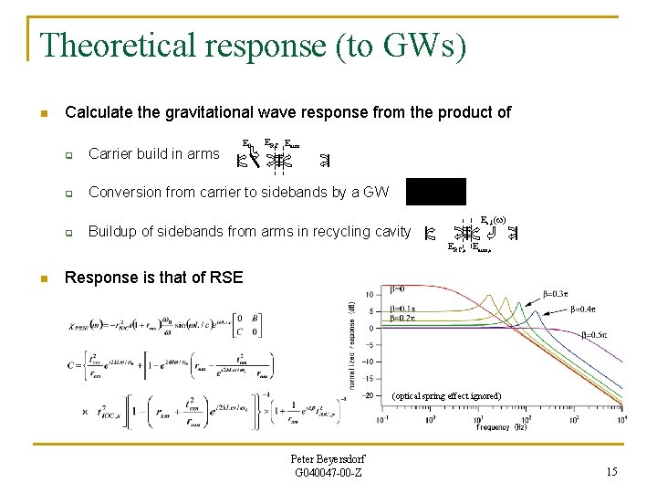
Theoretical response (to GWs) n Calculate the gravitational wave response from the product of E 0 ERC Earm q Carrier build in arms q Conversion from carrier to sidebands by a GW q Buildup of sidebands from arms in recycling cavity Es, 1(w) ERC, s Earm, s n Response is that of RSE (optical spring effect ignored) Peter Beyersdorf G 040047 -00 -Z 15
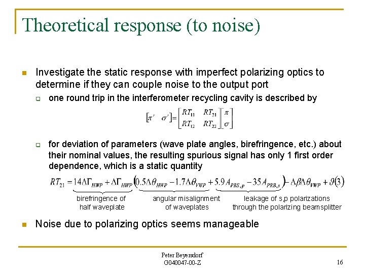
Theoretical response (to noise) n Investigate the static response with imperfect polarizing optics to determine if they can couple noise to the output port q q one round trip in the interferometer recycling cavity is described by for deviation of parameters (wave plate angles, birefringence, etc. ) about their nominal values, the resulting spurious signal has only 1 first order dependence, which is a static quantity birefringence of half waveplate n angular misalignment of waveplates leakage of s, p polarizations through the polarizing beamsplitter Noise due to polarizing optics seems manageable Peter Beyersdorf G 040047 -00 -Z 16
Unique aspects of the polarization RSE operation n n The use of an orthogonally polarized local oscillator for generating control signals Control of a Michelson without asymmetry q n n not necessary, but can reduce coupling of laser frequency noise to signal Differential tuning of a birefringent cavity Creating polarization sensitive finesse for a linear cavity Peter Beyersdorf G 040047 -00 -Z 17
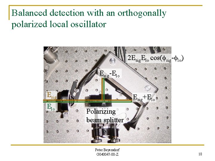
Balanced detection with an orthogonally polarized local oscillator 2 Esig. Elo cos(fsig-flo) Esig-Elo Esig+Elo Polarizing beam splitter Peter Beyersdorf G 040047 -00 -Z 18
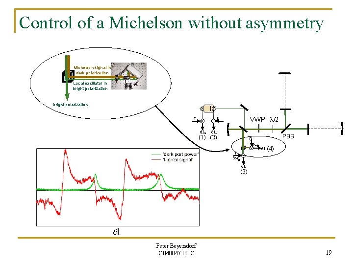
Control of a Michelson without asymmetry Michelson signal in dark polarization Local oscillator in bright polarization I VWP l/2 Q d. L+ d. L- (1) (2) Q I 3 wrf PBS 3 wrf dl- (4) dl+ (3) dl. Peter Beyersdorf G 040047 -00 -Z 19
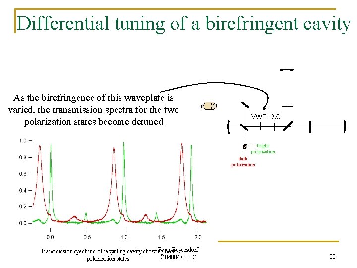
Differential tuning of a birefringent cavity As the birefringence of this waveplate is varied, the transmission spectra for the two polarization states become detuned VWP l/2 bright polarization dark polarization Peter Beyersdorf Transmission spectrum of recycling cavity showing both G 040047 -00 -Z polarization states 20
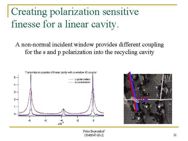
Creating polarization sensitive finesse for a linear cavity. A non-normal incident window provides different coupling for the s and p polarization into the recycling cavity Peter Beyersdorf G 040047 -00 -Z 21
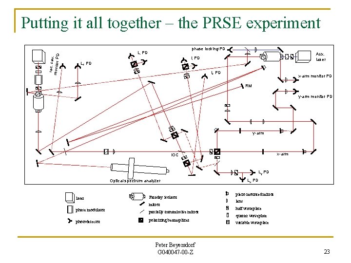
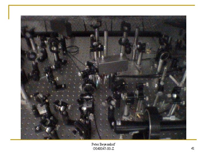
rec. cav. monitor P D Putting it all together – the PRSE experiment phase locking PD L- PD Aux. laser l- PD L+ PD l+ PD x-arm monitor PD RM y-arm monitor PD y-arm x-arm IOC Ly PD Lx PD Optical spectrum analyzer laser Faraday isolator mirror phase modulator partially transmissive mirror photodetector polarizing beamsplitter Peter Beyersdorf G 040047 -00 -Z piezo mounted mirror lens half waveplate quarter waveplate variable waveplate 23
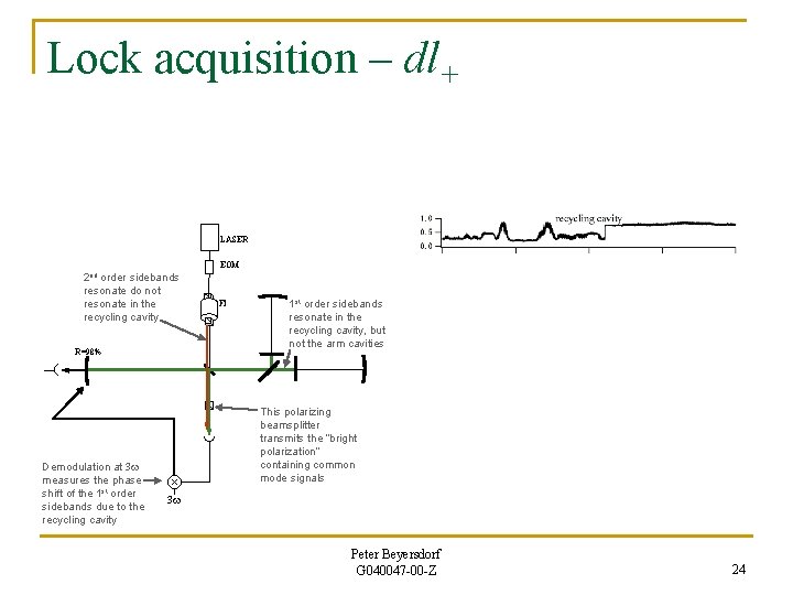
Lock acquisition – dl+ LASER EOM 2 nd order sidebands resonate do not resonate in the recycling cavity R=98% Demodulation at 3 w measures the phase shift of the 1 st order sidebands due to the recycling cavity FI 1 st order sidebands resonate in the recycling cavity, but not the arm cavities This polarizing beamsplitter transmits the “bright polarization” containing common mode signals 3 w Peter Beyersdorf G 040047 -00 -Z 24
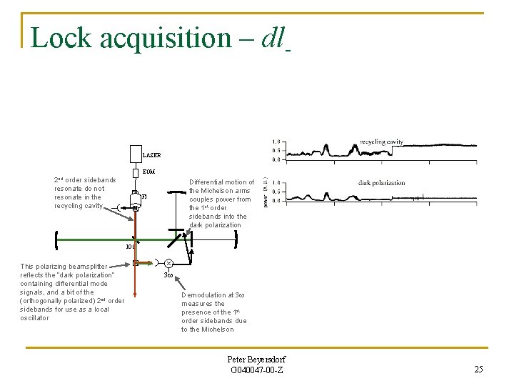
Lock acquisition – dl- LASER EOM 2 nd order sidebands resonate do not resonate in the recycling cavity Differential motion of the Michelson arms couples power from the 1 st order sidebands into the dark polarization FI IOC This polarizing beamsplitter reflects the “dark polarization” containing differential mode signals, and a bit of the (orthogonally polarized) 2 nd order sidebands for use as a local oscillator 3 w Demodulation at 3 w measures the presence of the 1 st order sidebands due to the Michelson Peter Beyersdorf G 040047 -00 -Z 25
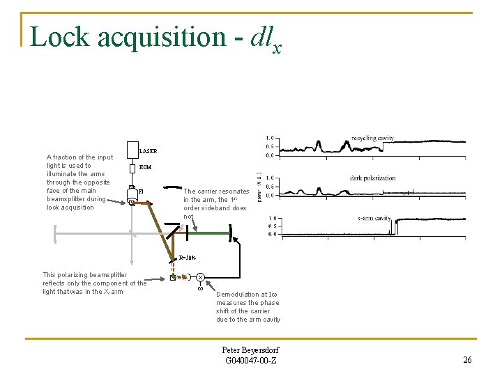
Lock acquisition - dlx A fraction of the input light is used to illuminate the arms through the opposite face of the main beamsplitter during lock acquisition LASER EOM FI The carrier resonates in the arm, the 1 st order sideband does not R=50% This polarizing beamsplitter reflects only the component of the light that was in the X-arm w Demodulation at 1 w measures the phase shift of the carrier due to the arm cavity Peter Beyersdorf G 040047 -00 -Z 26
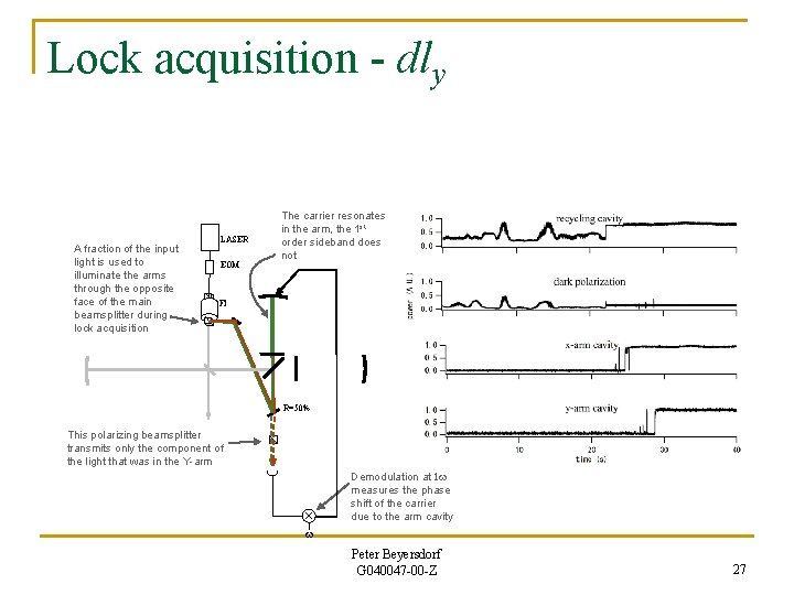
Lock acquisition - dly A fraction of the input light is used to illuminate the arms through the opposite face of the main beamsplitter during lock acquisition LASER EOM The carrier resonates in the arm, the 1 st order sideband does not FI R=50% This polarizing beamsplitter transmits only the component of the light that was in the Y-arm Demodulation at 1 w measures the phase shift of the carrier due to the arm cavity w Peter Beyersdorf G 040047 -00 -Z 27
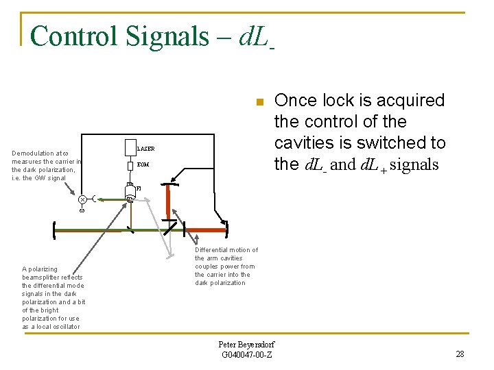
Control Signals – d. Ln Demodulation at w measures the carrier in the dark polarization, i. e. the GW signal LASER EOM Once lock is acquired the control of the cavities is switched to the d. L- and d. L+ signals FI w A polarizing beamsplitter reflects the differential mode signals in the dark polarization and a bit of the bright polarization for use as a local oscillator Differential motion of the arm cavities couples power from the carrier into the dark polarization Peter Beyersdorf G 040047 -00 -Z 28
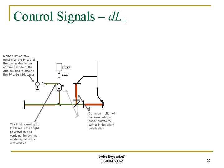
Control Signals – d. L+ Demodulation at w measures the phase of the carrier due to the common mode of the arm cavities relative to the 1 st order sidebands LASER EOM FI w The light returning to the laser is the bright polarization and contains the common mode signal of the arm cavities. Common motion of the arms adds a phase shift to the carrier in the bright polarization Peter Beyersdorf G 040047 -00 -Z 29
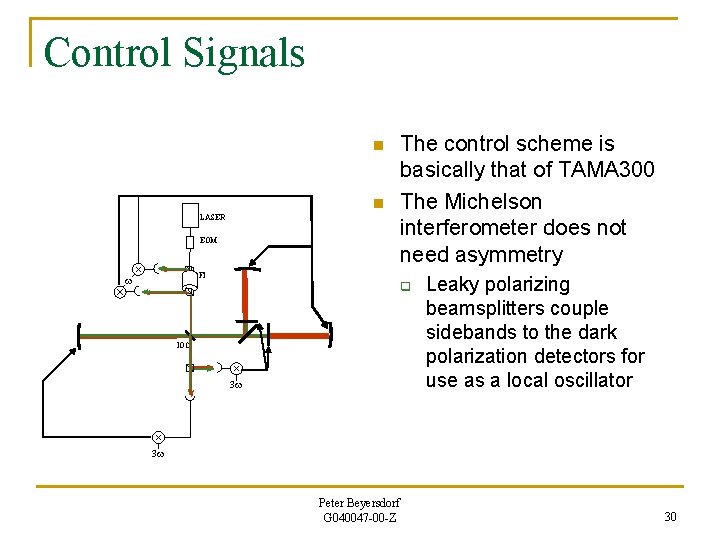
Control Signals n n LASER EOM The control scheme is basically that of TAMA 300 The Michelson interferometer does not need asymmetry FI w q IOC 3 w Leaky polarizing beamsplitters couple sidebands to the dark polarization detectors for use as a local oscillator 3 w Peter Beyersdorf G 040047 -00 -Z 30
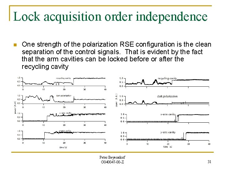
Lock acquisition order independence n One strength of the polarization RSE configuration is the clean separation of the control signals. That is evident by the fact that the arm cavities can be locked before or after the recycling cavity Peter Beyersdorf G 040047 -00 -Z 31
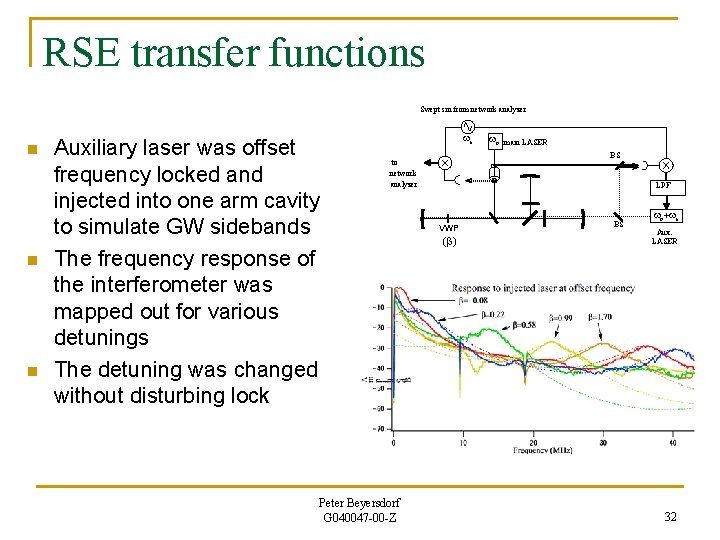
RSE transfer functions Swept sin from network analyzer n n n Auxiliary laser was offset frequency locked and injected into one arm cavity to simulate GW sidebands The frequency response of the interferometer was mapped out for various detunings The detuning was changed without disturbing lock ws main LASER BS to network analyzer Peter Beyersdorf G 040047 -00 -Z wo LPF VWP (b) BS wo+ws Aux. LASER 32
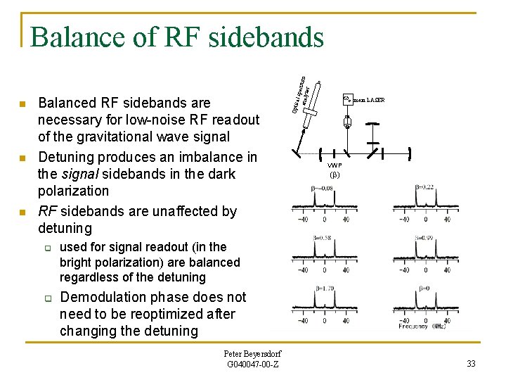
n n Balanced RF sidebands are necessary for low-noise RF readout of the gravitational wave signal Detuning produces an imbalance in the signal sidebands in the dark polarization RF sidebands are unaffected by detuning q q wo Optic n al spe analy ctrum zer Balance of RF sidebands main LASER VWP (b) used for signal readout (in the bright polarization) are balanced regardless of the detuning Demodulation phase does not need to be reoptimized after changing the detuning Peter Beyersdorf G 040047 -00 -Z 33
Discussion n n The polarization RSE configuration offers many advantages over other RSE configurations q Simple, familiar control scheme q RF readout without excess noise q Can operate without Shnupp asymmetry, reducing noise and control loop couplings q Variable bandwidth and continuously tunable peak frequency without breaking lock The cost of these advantages is the use of polarizing optics q Tolerances need to be set for several parameters that can couple noise to the output q High quality polarizing optics need to be developed and characterized q Computer models for interferometer analysis need to be modified to be able to represent this configuration Peter Beyersdorf G 040047 -00 -Z 34
Summary n n n A TAMA 300 -like control scheme was used to control a polarization RSE interferometer The frequency response is continuously adjustable Lock acquisition and control were robust and unaffected by the frequency tuning RF readout can be implemented without introducing excess noise Implementation will require extensive use of polarizing optics, which haven’t been used in a gravitational wave detector before Peter Beyersdorf G 040047 -00 -Z 36
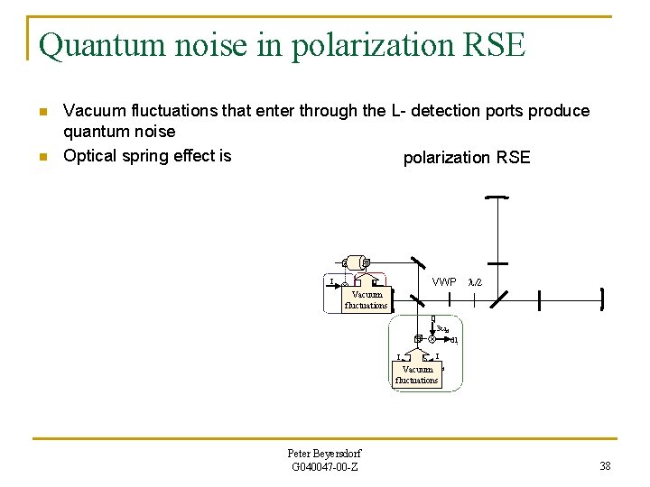
Quantum noise in polarization RSE n n Vacuum fluctuations that enter through the L- detection ports produce quantum noise Optical spring effect is polarization RSE I VWP Q l/2 Vacuum d. Lfluctuations d. L + Q 3 wrf dl- I I 3 w Vacuum rf fluctuations d. L+ dl+ Peter Beyersdorf G 040047 -00 -Z 38
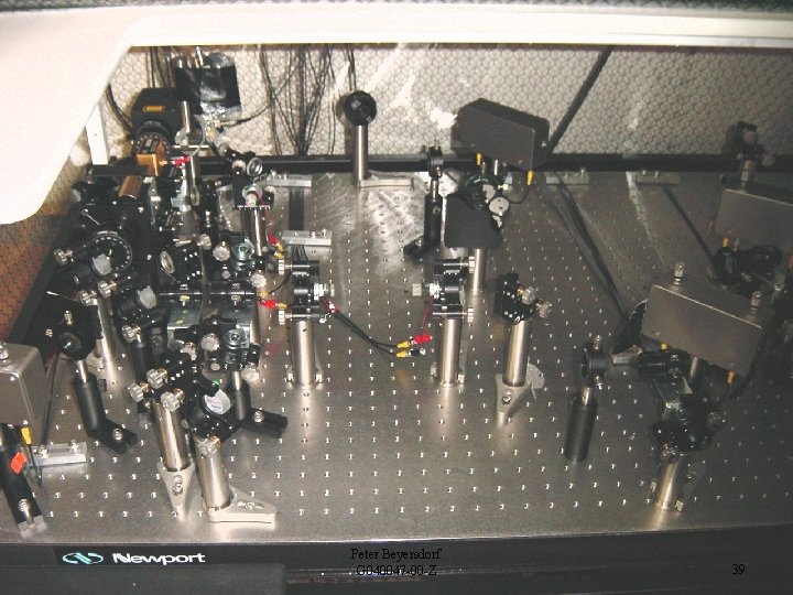
Peter Beyersdorf G 040047 -00 -Z 39
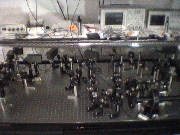
Peter Beyersdorf G 040047 -00 -Z 40
Peter Beyersdorf G 040047 -00 -Z 41
- Slides: 33