
The Physical Layer Chapter 2 Theoretical Basis for

The Physical Layer Chapter 2 • • Theoretical Basis for Data Communications Guided Transmission Media Wireless Transmission Communication Satellites Digital Modulation and Multiplexing Public Switched Telephone Network Mobile Telephone System Cable Television Revised: February 2018 CN 5 E by Tanenbaum & Wetherall, © Pearson Education-Prentice Hall and D. Wetherall, 2011
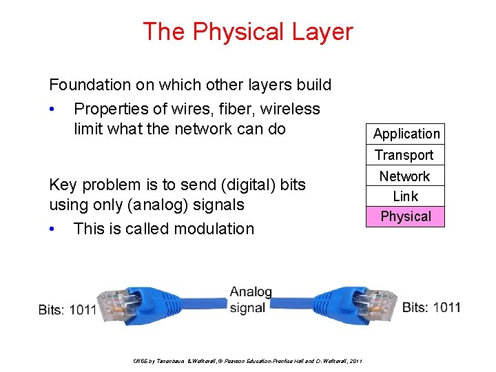
The Physical Layer Foundation on which other layers build • Properties of wires, fiber, wireless limit what the network can do Application Transport Key problem is to send (digital) bits using only (analog) signals • This is called modulation CN 5 E by Tanenbaum & Wetherall, © Pearson Education-Prentice Hall and D. Wetherall, 2011 Network Link Physical
Physical Layer Issues • • Media: wires, fiber, satellites, radio Signal propagation: bandwidth, attenuation, noise Modulation: how bits are represented as voltage signals Fundamental limits: Nyquist, Shannon CN 5 E by Tanenbaum & Wetherall, © Pearson Education-Prentice Hall and D. Wetherall, 2011
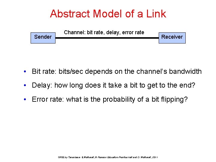
Abstract Model of a Link Sender Channel: bit rate, delay, error rate Receiver • Bit rate: bits/sec depends on the channel’s bandwidth • Delay: how long does it take a bit to get to the end? • Error rate: what is the probability of a bit flipping? CN 5 E by Tanenbaum & Wetherall, © Pearson Education-Prentice Hall and D. Wetherall, 2011

Bandwidth-Delay Product • Bits have a physical size on the channel! • Storage capacity of a channel is: bit rate x delay • Example: • 100 Mbps 5000 -km fiber, delay = 50 msec • In 50 msec we can pump out 5 million bits • So the fiber can store 5 million bits in 5000 km • 1 km holds 1000 bits so a bit is 1 meter long • At 200 Mbps, a bit is 0. 5 m long CN 5 E by Tanenbaum & Wetherall, © Pearson Education-Prentice Hall and D. Wetherall, 2011
Signal Propagation over a Wire • The signal has a finite propagation speed (2/3 c) • The signal is attenuated per km • Frequencies above a cutoff are strongly reduced • Noise is added to the signal CN 5 E by Tanenbaum & Wetherall, © Pearson Education-Prentice Hall and D. Wetherall, 2011
Theoretical Basis for Data Communication rates have fundamental limits • • • Fourier analysis Bandwidth-limited signals Maximum data rate of a channel CN 5 E by Tanenbaum & Wetherall, © Pearson Education-Prentice Hall and D. Wetherall, 2011
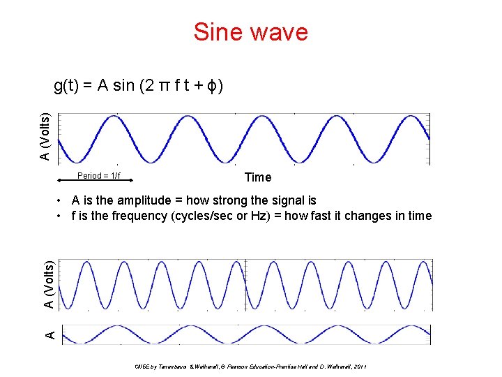
Sine wave A (Volts) g(t) = A sin (2 π f t + ϕ) Period = 1/f Time A A (Volts) • A is the amplitude = how strong the signal is • f is the frequency (cycles/sec or Hz) = how fast it changes in time CN 5 E by Tanenbaum & Wetherall, © Pearson Education-Prentice Hall and D. Wetherall, 2011
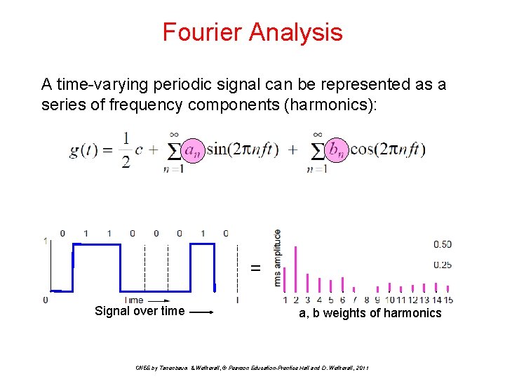
Fourier Analysis A time-varying periodic signal can be represented as a series of frequency components (harmonics): = Signal over time a, b weights of harmonics CN 5 E by Tanenbaum & Wetherall, © Pearson Education-Prentice Hall and D. Wetherall, 2011
Bandwidth • • At the signal level, bandwidth is cutoff frequency (HZ) For data transmission it is bits/sec CN 5 E by Tanenbaum & Wetherall, © Pearson Education-Prentice Hall and D. Wetherall, 2011
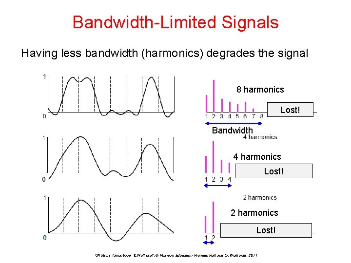
Bandwidth-Limited Signals Having less bandwidth (harmonics) degrades the signal 8 harmonics Lost! Bandwidth 4 harmonics Lost! 2 harmonics Lost! CN 5 E by Tanenbaum & Wetherall, © Pearson Education-Prentice Hall and D. Wetherall, 2011
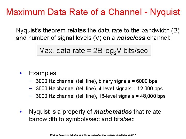
Maximum Data Rate of a Channel - Nyquist’s theorem relates the data rate to the bandwidth (B) and number of signal levels (V) on a noiseless channel: Max. data rate = 2 B log 2 V bits/sec • Examples − 3000 Hz channel (tel. line), binary signals = 6000 bps − 3000 Hz channel (tel. line), 4 -level signals = 12, 000 bps − 3000 Hz channel (tel. line), 16 -level signals = 48, 000 bps • Nyquist is a property of mathematics that relate bandwidth to symbols/sec and bits/sec CN 5 E by Tanenbaum & Wetherall, © Pearson Education-Prentice Hall and D. Wetherall, 2011
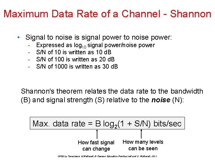
Maximum Data Rate of a Channel - Shannon • Signal to noise is signal power to noise power: - Expressed as log 10 signal power/noise power S/N of 10 is written as 10 d. B S/N of 100 is written as 20 d. B S/N of 1000 is written as 30 d. B Shannon's theorem relates the data rate to the bandwidth (B) and signal strength (S) relative to the noise (N): Max. data rate = B log 2(1 + S/N) bits/sec How fast signal can change How many levels can be seen CN 5 E by Tanenbaum & Wetherall, © Pearson Education-Prentice Hall and D. Wetherall, 2011
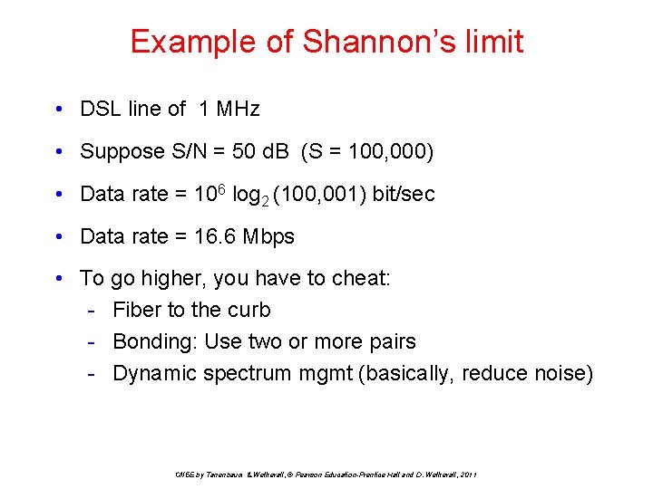
Example of Shannon’s limit • DSL line of 1 MHz • Suppose S/N = 50 d. B (S = 100, 000) • Data rate = 106 log 2 (100, 001) bit/sec • Data rate = 16. 6 Mbps • To go higher, you have to cheat: - Fiber to the curb - Bonding: Use two or more pairs - Dynamic spectrum mgmt (basically, reduce noise) CN 5 E by Tanenbaum & Wetherall, © Pearson Education-Prentice Hall and D. Wetherall, 2011
Nyquist vs. Shannon • Nyquist: - For noiseless channel - Depends on number signal levels per symbol • Shannon - For noisy channel - Depends on S/N ratio, not bits/symbol CN 5 E by Tanenbaum & Wetherall, © Pearson Education-Prentice Hall and D. Wetherall, 2011
Guided Transmission (Wires & Fiber) Media have different properties, hence performance • Reality check − Physical transport of storage media • Wires: − Twisted pairs − Coaxial cable − Power lines • Fiber cables CN 5 E by Tanenbaum & Wetherall, © Pearson Education-Prentice Hall and D. Wetherall, 2011
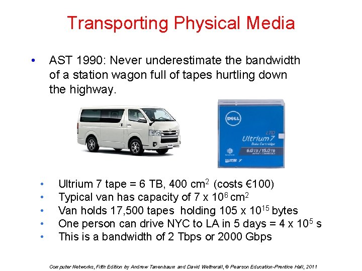
Transporting Physical Media • AST 1990: Never underestimate the bandwidth of a station wagon full of tapes hurtling down the highway. • • • Ultrium 7 tape = 6 TB, 400 cm 2 (costs € 100) Typical van has capacity of 7 x 106 cm 2 Van holds 17, 500 tapes holding 105 x 1015 bytes One person can drive NYC to LA in 5 days = 4 x 10⁵ s This is a bandwidth of 2 Tbps or 2000 Gbps Computer Networks, Fifth Edition by Andrew Tanenbaum and David Wetherall, © Pearson Education-Prentice Hall, 2011
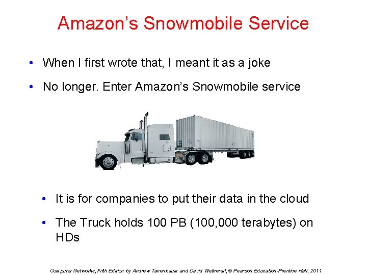
Amazon’s Snowmobile Service • When I first wrote that, I meant it as a joke • No longer. Enter Amazon’s Snowmobile service • It is for companies to put their data in the cloud • The Truck holds 100 PB (100, 000 terabytes) on HDs Computer Networks, Fifth Edition by Andrew Tanenbaum and David Wetherall, © Pearson Education-Prentice Hall, 2011
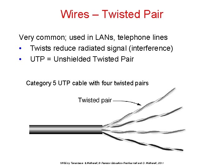
Wires – Twisted Pair Very common; used in LANs, telephone lines • Twists reduce radiated signal (interference) • UTP = Unshielded Twisted Pair Category 5 UTP cable with four twisted pairs CN 5 E by Tanenbaum & Wetherall, © Pearson Education-Prentice Hall and D. Wetherall, 2011
Kinds of Wire • STP = Shielded Twisted Pair • UTP = Unshielded Twisted Pair - Cat 3: Home telephone lines - Cat 5: Fast Ethernet (100 Mbps) - Cat 5 e: Gigabit Ethernet (1 Gbps) - Cat 6: 10 -Gigabit Ethernet (10 Gps) up to 100 m - Cat 6 A: Better quality Cat 6 - Cat 7: Includes shielding (not in common use) CN 5 E by Tanenbaum & Wetherall, © Pearson Education-Prentice Hall and D. Wetherall, 2011
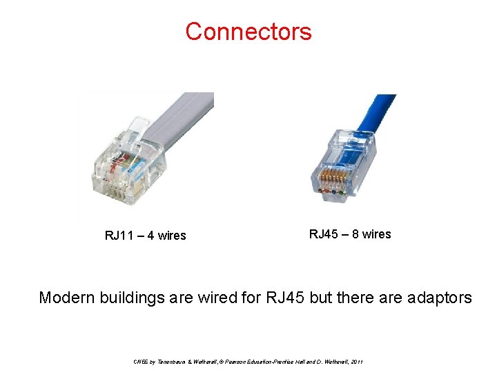
Connectors RJ 11 – 4 wires RJ 45 – 8 wires Modern buildings are wired for RJ 45 but there adaptors CN 5 E by Tanenbaum & Wetherall, © Pearson Education-Prentice Hall and D. Wetherall, 2011
Link Terminology Simplex link • Only one fixed direction at all times; not common Half-duplex link • Both directions, but not at the same time • e. g. , senders take turns on a wireless channel Full-duplex link • Used for transmission in both directions at once • e. g. , use different twisted pairs for each direction CN 5 E by Tanenbaum & Wetherall, © Pearson Education-Prentice Hall and D. Wetherall, 2011
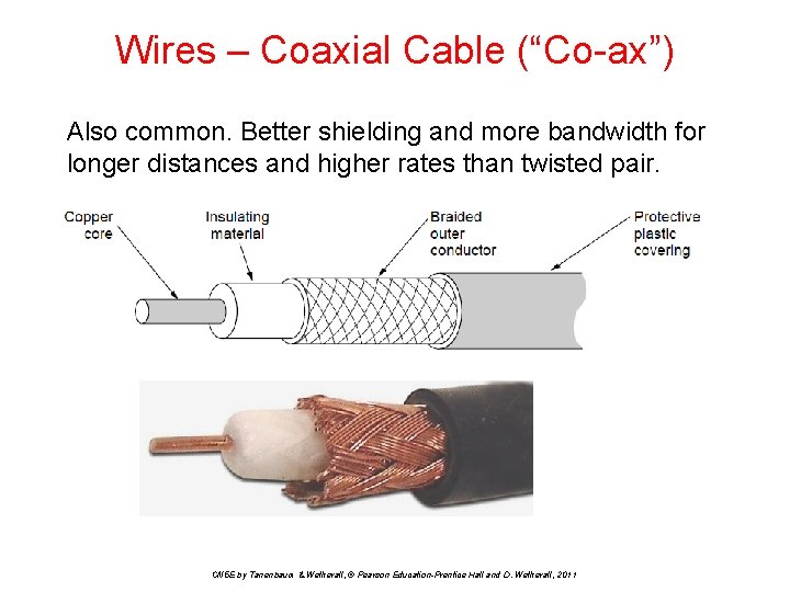
Wires – Coaxial Cable (“Co-ax”) Also common. Better shielding and more bandwidth for longer distances and higher rates than twisted pair. CN 5 E by Tanenbaum & Wetherall, © Pearson Education-Prentice Hall and D. Wetherall, 2011
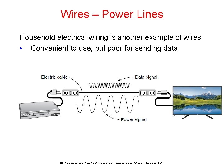
Wires – Power Lines Household electrical wiring is another example of wires • Convenient to use, but poor for sending data CN 5 E by Tanenbaum & Wetherall, © Pearson Education-Prentice Hall and D. Wetherall, 2011
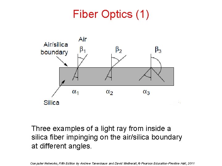
Fiber Optics (1) Three examples of a light ray from inside a silica fiber impinging on the air/silica boundary at different angles. Computer Networks, Fifth Edition by Andrew Tanenbaum and David Wetherall, © Pearson Education-Prentice Hall, 2011
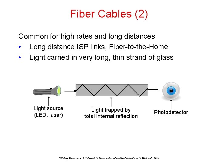
Fiber Cables (2) Common for high rates and long distances • Long distance ISP links, Fiber-to-the-Home • Light carried in very long, thin strand of glass Light source (LED, laser) Light trapped by total internal reflection Photodetector CN 5 E by Tanenbaum & Wetherall, © Pearson Education-Prentice Hall and D. Wetherall, 2011
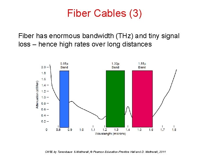
Fiber Cables (3) Fiber has enormous bandwidth (THz) and tiny signal loss – hence high rates over long distances CN 5 E by Tanenbaum & Wetherall, © Pearson Education-Prentice Hall and D. Wetherall, 2011
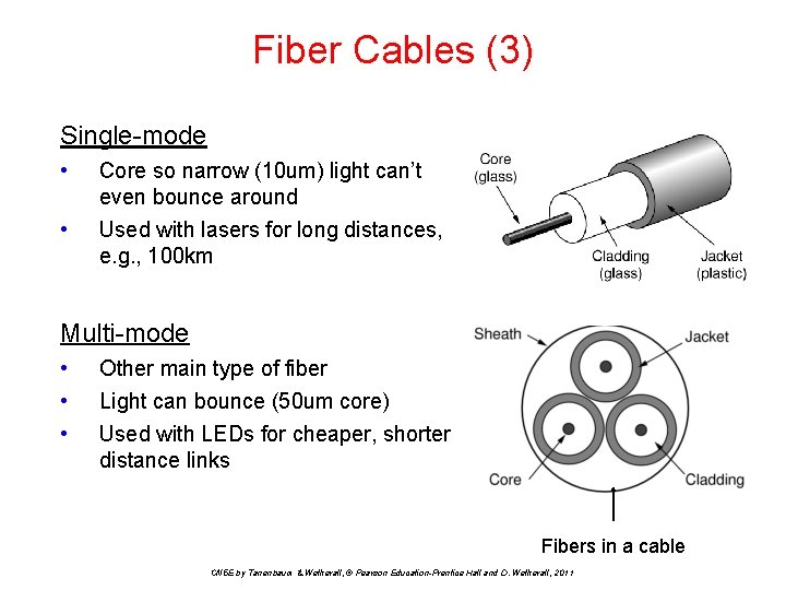
Fiber Cables (3) Single-mode • • Core so narrow (10 um) light can’t even bounce around Used with lasers for long distances, e. g. , 100 km Multi-mode • • • Other main type of fiber Light can bounce (50 um core) Used with LEDs for cheaper, shorter distance links Fibers in a cable CN 5 E by Tanenbaum & Wetherall, © Pearson Education-Prentice Hall and D. Wetherall, 2011
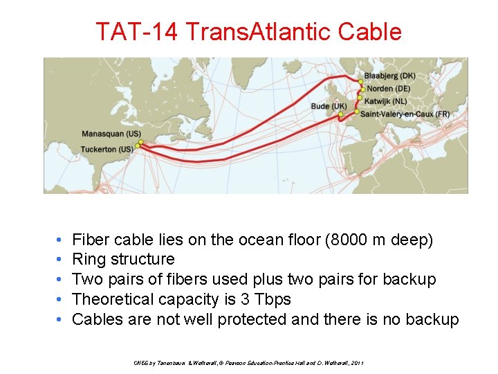
TAT-14 Trans. Atlantic Cable • • • Fiber cable lies on the ocean floor (8000 m deep) Ring structure Two pairs of fibers used plus two pairs for backup Theoretical capacity is 3 Tbps Cables are not well protected and there is no backup CN 5 E by Tanenbaum & Wetherall, © Pearson Education-Prentice Hall and D. Wetherall, 2011
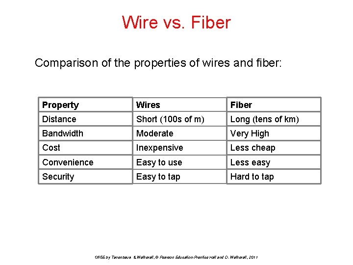
Wire vs. Fiber Comparison of the properties of wires and fiber: Property Wires Fiber Distance Short (100 s of m) Long (tens of km) Bandwidth Moderate Very High Cost Inexpensive Less cheap Convenience Easy to use Less easy Security Easy to tap Hard to tap CN 5 E by Tanenbaum & Wetherall, © Pearson Education-Prentice Hall and D. Wetherall, 2011
Wireless Transmission • • • Electromagnetic Spectrum Radio Transmission Microwave Transmission Light Transmission Wireless vs. Wires/Fiber CN 5 E by Tanenbaum & Wetherall, © Pearson Education-Prentice Hall and D. Wetherall, 2011
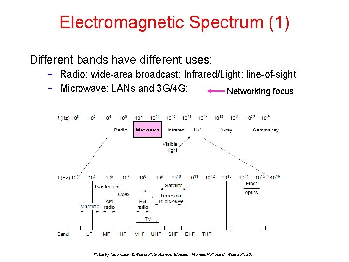
Electromagnetic Spectrum (1) Different bands have different uses: − Radio: wide-area broadcast; Infrared/Light: line-of-sight − Microwave: LANs and 3 G/4 G; Networking focus Microwave CN 5 E by Tanenbaum & Wetherall, © Pearson Education-Prentice Hall and D. Wetherall, 2011
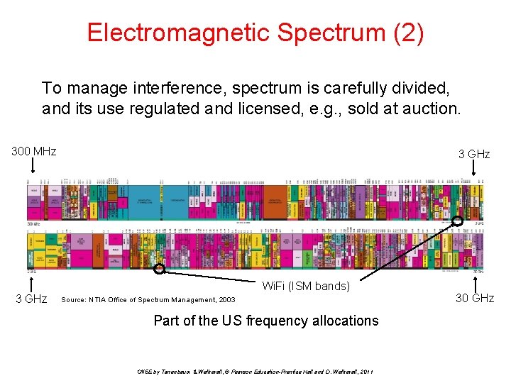
Electromagnetic Spectrum (2) To manage interference, spectrum is carefully divided, and its use regulated and licensed, e. g. , sold at auction. 300 MHz 3 GHz Wi. Fi (ISM bands) 3 GHz Source: NTIA Office of Spectrum Management, 2003 Part of the US frequency allocations CN 5 E by Tanenbaum & Wetherall, © Pearson Education-Prentice Hall and D. Wetherall, 2011 30 GHz
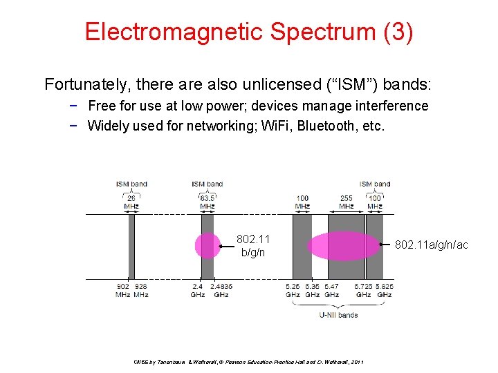
Electromagnetic Spectrum (3) Fortunately, there also unlicensed (“ISM”) bands: − Free for use at low power; devices manage interference − Widely used for networking; Wi. Fi, Bluetooth, etc. 802. 11 b/g/n CN 5 E by Tanenbaum & Wetherall, © Pearson Education-Prentice Hall and D. Wetherall, 2011 802. 11 a/g/n/ac
Radio Waves • • • Radio waves have a frequency, f, in Hz They have a wavelength, λ in meters λf = c in vacuum Speed of radio/light = 1 foot/nsec For microwaves, megahertz x meters = 300 − 300 MHz waves are 1 meter long − 1 GHz waves are 30 cm long − 2. 4 GHz waves are 12. 5 cm long CN 5 E by Tanenbaum & Wetherall, © Pearson Education-Prentice Hall and D. Wetherall, 2011
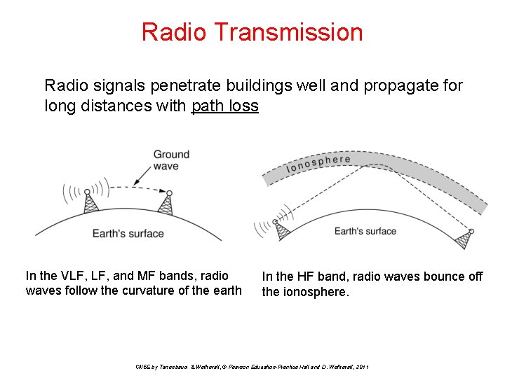
Radio Transmission Radio signals penetrate buildings well and propagate for long distances with path loss In the VLF, and MF bands, radio waves follow the curvature of the earth In the HF band, radio waves bounce off the ionosphere. CN 5 E by Tanenbaum & Wetherall, © Pearson Education-Prentice Hall and D. Wetherall, 2011
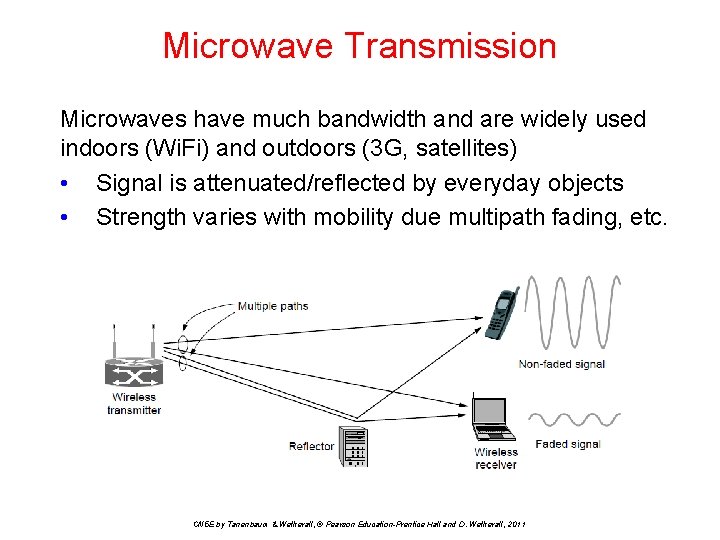
Microwave Transmission Microwaves have much bandwidth and are widely used indoors (Wi. Fi) and outdoors (3 G, satellites) • Signal is attenuated/reflected by everyday objects • Strength varies with mobility due multipath fading, etc. CN 5 E by Tanenbaum & Wetherall, © Pearson Education-Prentice Hall and D. Wetherall, 2011
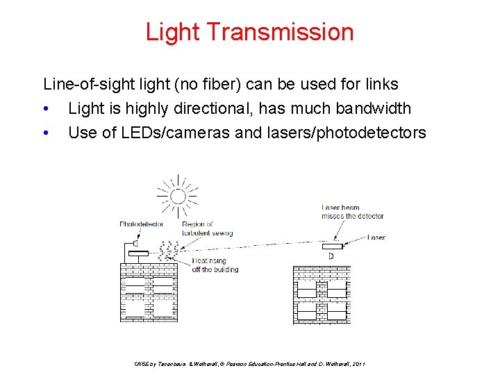
Light Transmission Line-of-sight light (no fiber) can be used for links • Light is highly directional, has much bandwidth • Use of LEDs/cameras and lasers/photodetectors CN 5 E by Tanenbaum & Wetherall, © Pearson Education-Prentice Hall and D. Wetherall, 2011
Wireless vs. Wires/Fiber Wireless: + + + − − Easy and inexpensive to deploy Naturally supports mobility Naturally supports broadcast Transmissions interfere and must be managed Signal strengths hence data rates vary greatly Wires/Fiber: + Easy to engineer a fixed data rate over point-to-point links − Can be expensive to deploy, esp. over distances − Doesn’t readily support mobility or broadcast CN 5 E by Tanenbaum & Wetherall, © Pearson Education-Prentice Hall and D. Wetherall, 2011
Communication Satellites are effective for broadcast distribution and anywhere/anytime communications • • Kinds of Satellites Geostationary (GEO) Satellites Low-Earth Orbit (LEO) Satellites vs. Fiber CN 5 E by Tanenbaum & Wetherall, © Pearson Education-Prentice Hall and D. Wetherall, 2011
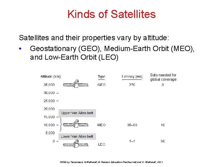
Kinds of Satellites and their properties vary by altitude: • Geostationary (GEO), Medium-Earth Orbit (MEO), and Low-Earth Orbit (LEO) Sats needed for global coverage CN 5 E by Tanenbaum & Wetherall, © Pearson Education-Prentice Hall and D. Wetherall, 2011
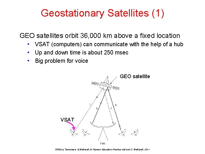
Geostationary Satellites (1) GEO satellites orbit 36, 000 km above a fixed location • VSAT (computers) can communicate with the help of a hub • Up and down time is about 250 msec • Big problem for voice GEO satellite VSAT CN 5 E by Tanenbaum & Wetherall, © Pearson Education-Prentice Hall and D. Wetherall, 2011
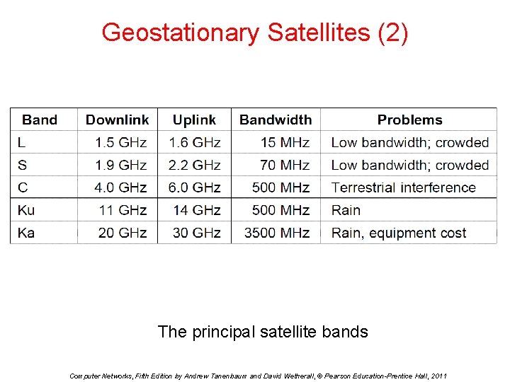
Geostationary Satellites (2) The principal satellite bands Computer Networks, Fifth Edition by Andrew Tanenbaum and David Wetherall, © Pearson Education-Prentice Hall, 2011
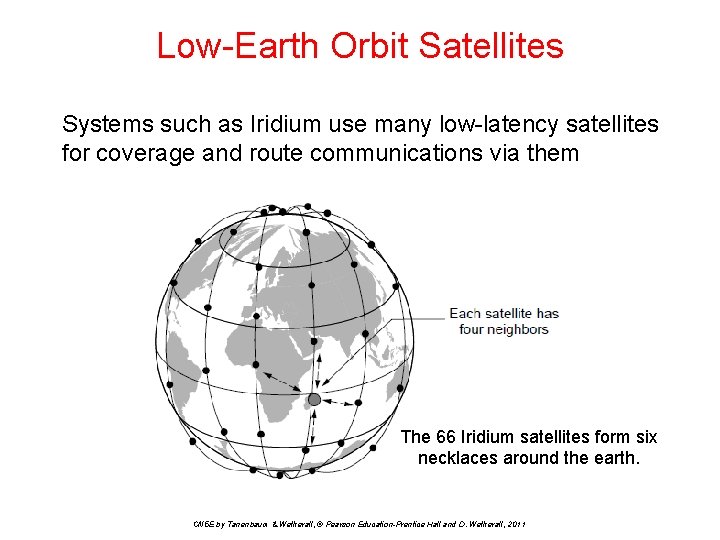
Low-Earth Orbit Satellites Systems such as Iridium use many low-latency satellites for coverage and route communications via them The 66 Iridium satellites form six necklaces around the earth. CN 5 E by Tanenbaum & Wetherall, © Pearson Education-Prentice Hall and D. Wetherall, 2011
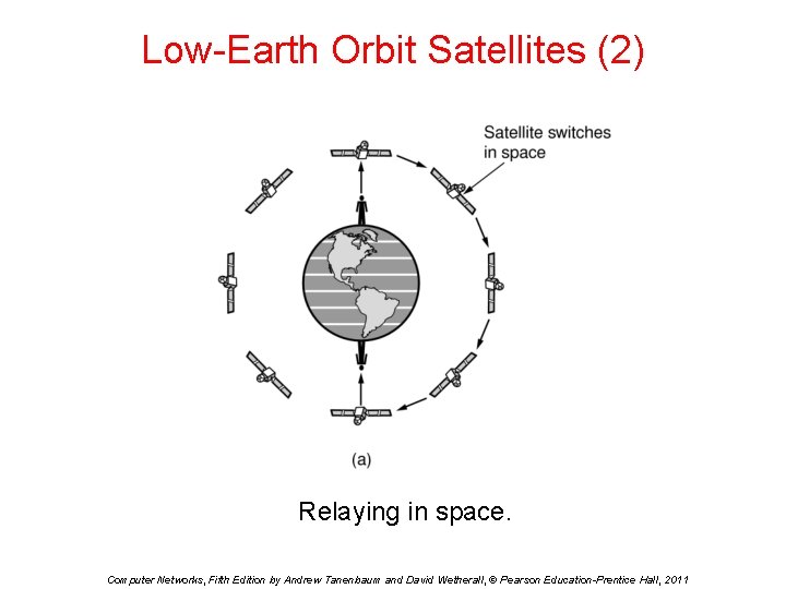
Low-Earth Orbit Satellites (2) Relaying in space. Computer Networks, Fifth Edition by Andrew Tanenbaum and David Wetherall, © Pearson Education-Prentice Hall, 2011
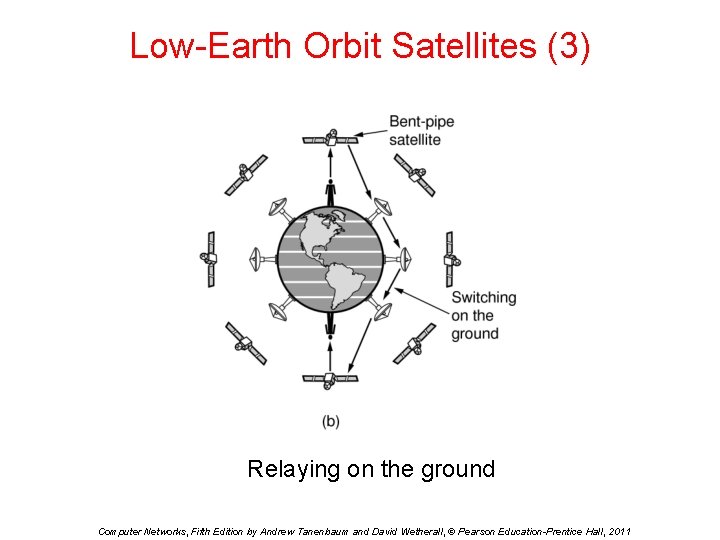
Low-Earth Orbit Satellites (3) Relaying on the ground Computer Networks, Fifth Edition by Andrew Tanenbaum and David Wetherall, © Pearson Education-Prentice Hall, 2011
Satellite vs. Fiber Satellite: + Can rapidly set up anywhere/anytime communications (after satellites have been launched) + Can broadcast to large regions − Limited bandwidth and interference to manage Fiber: + Enormous bandwidth over long distances − Installation can be more expensive/difficult − Doesn’t work at sea or in remote areas CN 5 E by Tanenbaum & Wetherall, © Pearson Education-Prentice Hall and D. Wetherall, 2011
Digital Modulation and Multiplexing Modulation schemes send bits as signals Multiplexing schemes share a channel among users. • • • Baseband Transmission Passband Transmission Frequency Division Multiplexing Time Division Multiplexing Code Division Multiple Access CN 5 E by Tanenbaum & Wetherall, © Pearson Education-Prentice Hall and D. Wetherall, 2011
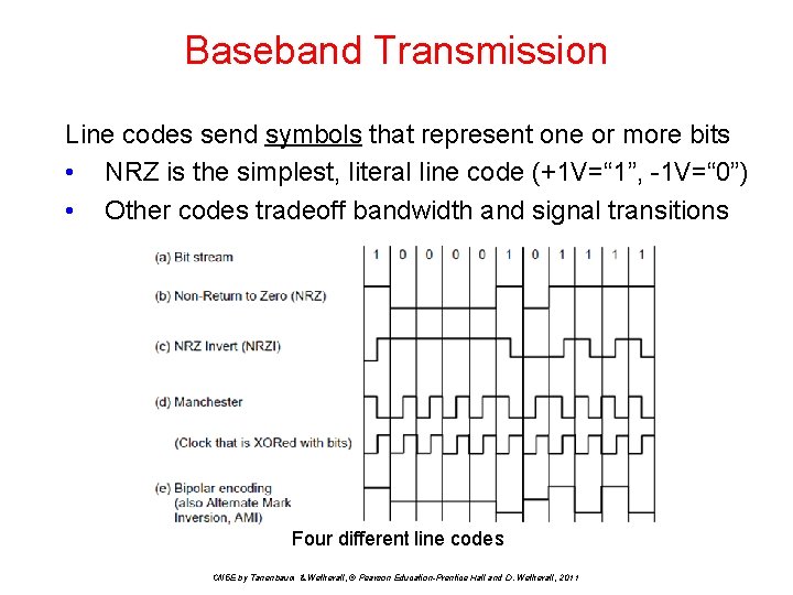
Baseband Transmission Line codes send symbols that represent one or more bits • NRZ is the simplest, literal line code (+1 V=“ 1”, -1 V=“ 0”) • Other codes tradeoff bandwidth and signal transitions Four different line codes CN 5 E by Tanenbaum & Wetherall, © Pearson Education-Prentice Hall and D. Wetherall, 2011
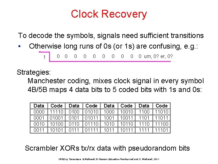
Clock Recovery To decode the symbols, signals need sufficient transitions • Otherwise long runs of 0 s (or 1 s) are confusing, e. g. : 1 0 0 0 0 0 0 um, 0? er, 0? Strategies: Manchester coding, mixes clock signal in every symbol 4 B/5 B maps 4 data bits to 5 coded bits with 1 s and 0 s: Data 0000 0001 0010 0011 Code 11110 01001 10100 10101 Data 0100 0101 0110 0111 Code 01010 01011 01110 01111 Data 1000 1001 1010 1011 Code 10010 10011 10110 10111 Data 1100 1101 1110 1111 Code 11010 11011 11100 11101 Scrambler XORs tx/rx data with pseudorandom bits CN 5 E by Tanenbaum & Wetherall, © Pearson Education-Prentice Hall and D. Wetherall, 2011
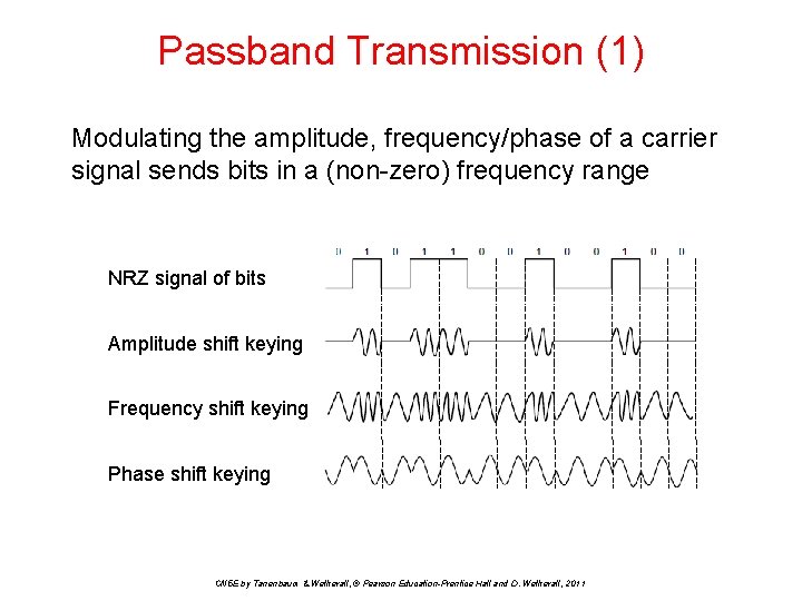
Passband Transmission (1) Modulating the amplitude, frequency/phase of a carrier signal sends bits in a (non-zero) frequency range NRZ signal of bits Amplitude shift keying Frequency shift keying Phase shift keying CN 5 E by Tanenbaum & Wetherall, © Pearson Education-Prentice Hall and D. Wetherall, 2011
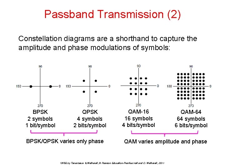
Passband Transmission (2) Constellation diagrams are a shorthand to capture the amplitude and phase modulations of symbols: BPSK 2 symbols 1 bit/symbol QPSK 4 symbols 2 bits/symbol BPSK/QPSK varies only phase QAM-16 16 symbols 4 bits/symbol QAM-64 64 symbols 6 bits/symbol QAM varies amplitude and phase CN 5 E by Tanenbaum & Wetherall, © Pearson Education-Prentice Hall and D. Wetherall, 2011
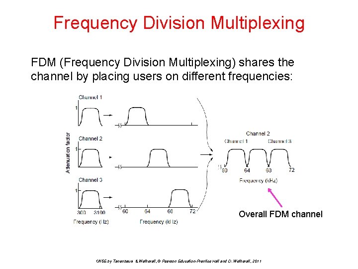
Frequency Division Multiplexing FDM (Frequency Division Multiplexing) shares the channel by placing users on different frequencies: Overall FDM channel CN 5 E by Tanenbaum & Wetherall, © Pearson Education-Prentice Hall and D. Wetherall, 2011
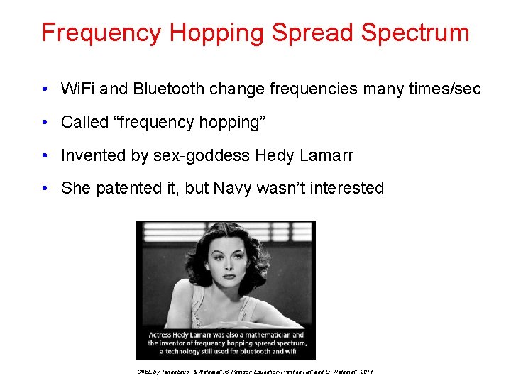
Frequency Hopping Spread Spectrum • Wi. Fi and Bluetooth change frequencies many times/sec • Called “frequency hopping” • Invented by sex-goddess Hedy Lamarr • She patented it, but Navy wasn’t interested CN 5 E by Tanenbaum & Wetherall, © Pearson Education-Prentice Hall and D. Wetherall, 2011
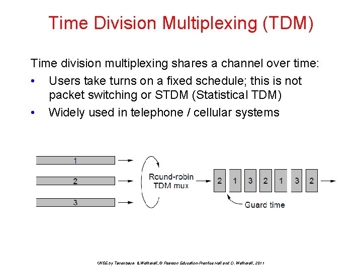
Time Division Multiplexing (TDM) Time division multiplexing shares a channel over time: • Users take turns on a fixed schedule; this is not packet switching or STDM (Statistical TDM) • Widely used in telephone / cellular systems CN 5 E by Tanenbaum & Wetherall, © Pearson Education-Prentice Hall and D. Wetherall, 2011
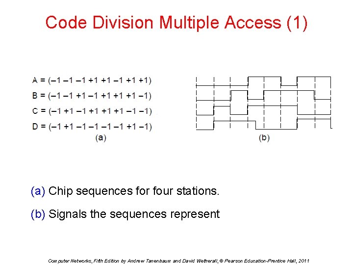
Code Division Multiple Access (1) (a) Chip sequences for four stations. (b) Signals the sequences represent Computer Networks, Fifth Edition by Andrew Tanenbaum and David Wetherall, © Pearson Education-Prentice Hall, 2011
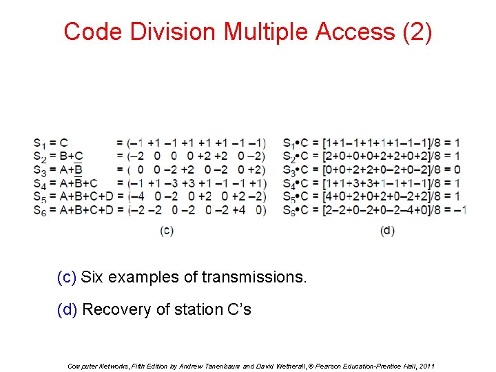
Code Division Multiple Access (2) (c) Six examples of transmissions. (d) Recovery of station C’s Computer Networks, Fifth Edition by Andrew Tanenbaum and David Wetherall, © Pearson Education-Prentice Hall, 2011
The Public Switched Telephone Network • • • Structure of the telephone system Politics of telephones Local loop: modems, ADSL, and Ftt. H Trunks and multiplexing Switching CN 5 E by Tanenbaum & Wetherall, © Pearson Education-Prentice Hall and D. Wetherall, 2011
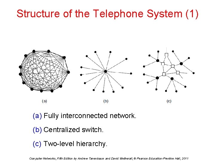
Structure of the Telephone System (1) (a) Fully interconnected network. (b) Centralized switch. (c) Two-level hierarchy. Computer Networks, Fifth Edition by Andrew Tanenbaum and David Wetherall, © Pearson Education-Prentice Hall, 2011
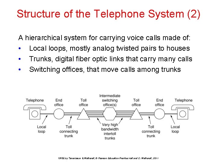
Structure of the Telephone System (2) A hierarchical system for carrying voice calls made of: • Local loops, mostly analog twisted pairs to houses • Trunks, digital fiber optic links that carry many calls • Switching offices, that move calls among trunks CN 5 E by Tanenbaum & Wetherall, © Pearson Education-Prentice Hall and D. Wetherall, 2011
Structure of the Telephone System (3) Major Components • Local loops analog twisted pairs to houses, businesses). • Trunks (digital fiber optic links between switching offices). • Switching offices (calls are moved from one trunk to another) • Core of phone system is optical & digital in Europe, US Computer Networks, Fifth Edition by Andrew Tanenbaum and David Wetherall, © Pearson Education-Prentice Hall, 2011
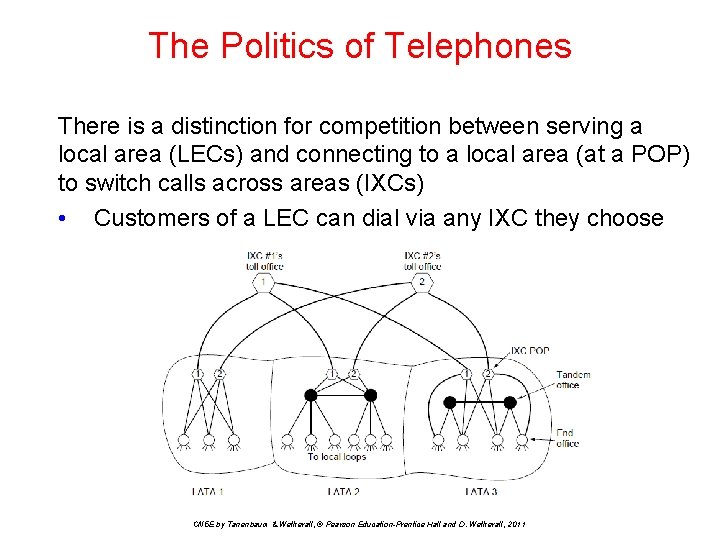
The Politics of Telephones There is a distinction for competition between serving a local area (LECs) and connecting to a local area (at a POP) to switch calls across areas (IXCs) • Customers of a LEC can dial via any IXC they choose CN 5 E by Tanenbaum & Wetherall, © Pearson Education-Prentice Hall and D. Wetherall, 2011
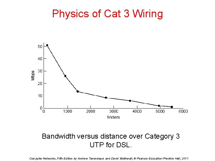
Physics of Cat 3 Wiring Bandwidth versus distance over Category 3 UTP for DSL. Computer Networks, Fifth Edition by Andrew Tanenbaum and David Wetherall, © Pearson Education-Prentice Hall, 2011
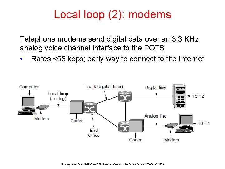
Local loop (2): modems Telephone modems send digital data over an 3. 3 KHz analog voice channel interface to the POTS • Rates <56 kbps; early way to connect to the Internet CN 5 E by Tanenbaum & Wetherall, © Pearson Education-Prentice Hall and D. Wetherall, 2011
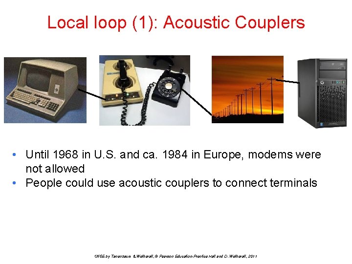
Local loop (1): Acoustic Couplers • Until 1968 in U. S. and ca. 1984 in Europe, modems were not allowed • People could use acoustic couplers to connect terminals CN 5 E by Tanenbaum & Wetherall, © Pearson Education-Prentice Hall and D. Wetherall, 2011
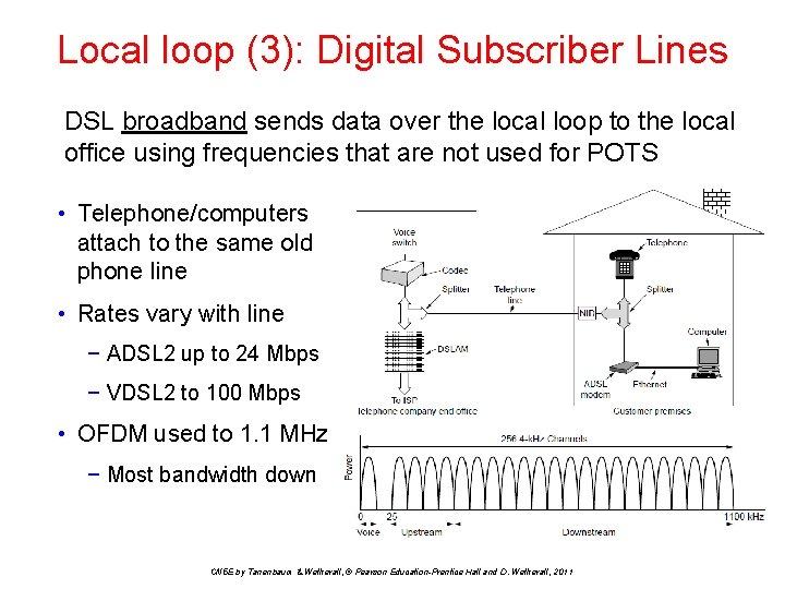
Local loop (3): Digital Subscriber Lines DSL broadband sends data over the local loop to the local office using frequencies that are not used for POTS • Telephone/computers attach to the same old phone line • Rates vary with line − ADSL 2 up to 24 Mbps − VDSL 2 to 100 Mbps • OFDM used to 1. 1 MHz − Most bandwidth down CN 5 E by Tanenbaum & Wetherall, © Pearson Education-Prentice Hall and D. Wetherall, 2011
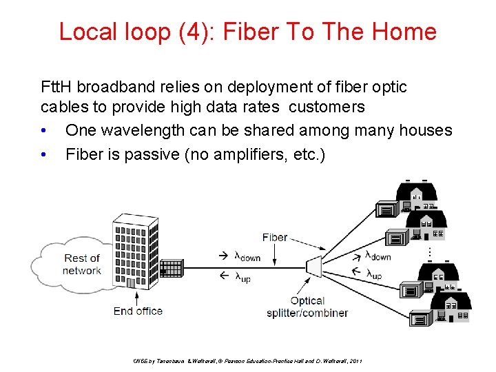
Local loop (4): Fiber To The Home Ftt. H broadband relies on deployment of fiber optic cables to provide high data rates customers • One wavelength can be shared among many houses • Fiber is passive (no amplifiers, etc. ) CN 5 E by Tanenbaum & Wetherall, © Pearson Education-Prentice Hall and D. Wetherall, 2011
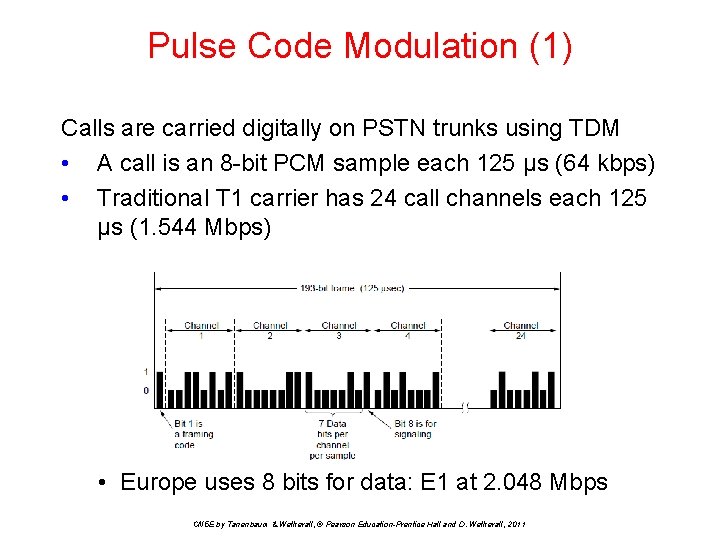
Pulse Code Modulation (1) Calls are carried digitally on PSTN trunks using TDM • A call is an 8 -bit PCM sample each 125 μs (64 kbps) • Traditional T 1 carrier has 24 call channels each 125 μs (1. 544 Mbps) • Europe uses 8 bits for data: E 1 at 2. 048 Mbps CN 5 E by Tanenbaum & Wetherall, © Pearson Education-Prentice Hall and D. Wetherall, 2011
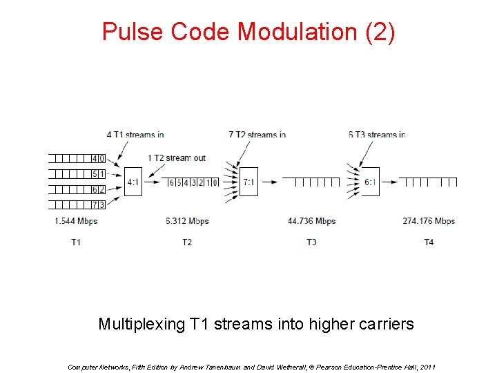
Pulse Code Modulation (2) Multiplexing T 1 streams into higher carriers Computer Networks, Fifth Edition by Andrew Tanenbaum and David Wetherall, © Pearson Education-Prentice Hall, 2011
SONET/SDH (1) • Different carriers had to interconnect • For international calls, T 3 and E 3 had to be harmonized • Need for standards above T 4 and E 4 • Better network management was needed CN 5 E by Tanenbaum & Wetherall, © Pearson Education-Prentice Hall and D. Wetherall, 2011
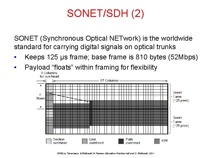
SONET/SDH (2) SONET (Synchronous Optical NETwork) is the worldwide standard for carrying digital signals on optical trunks • Keeps 125 μs frame; base frame is 810 bytes (52 Mbps) • Payload “floats” within framing for flexibility CN 5 E by Tanenbaum & Wetherall, © Pearson Education-Prentice Hall and D. Wetherall, 2011
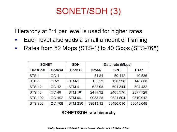
SONET/SDH (3) Hierarchy at 3: 1 per level is used for higher rates • Each level also adds a small amount of framing • Rates from 52 Mbps (STS-1) to 40 Gbps (STS-768) SONET/SDH rate hierarchy CN 5 E by Tanenbaum & Wetherall, © Pearson Education-Prentice Hall and D. Wetherall, 2011
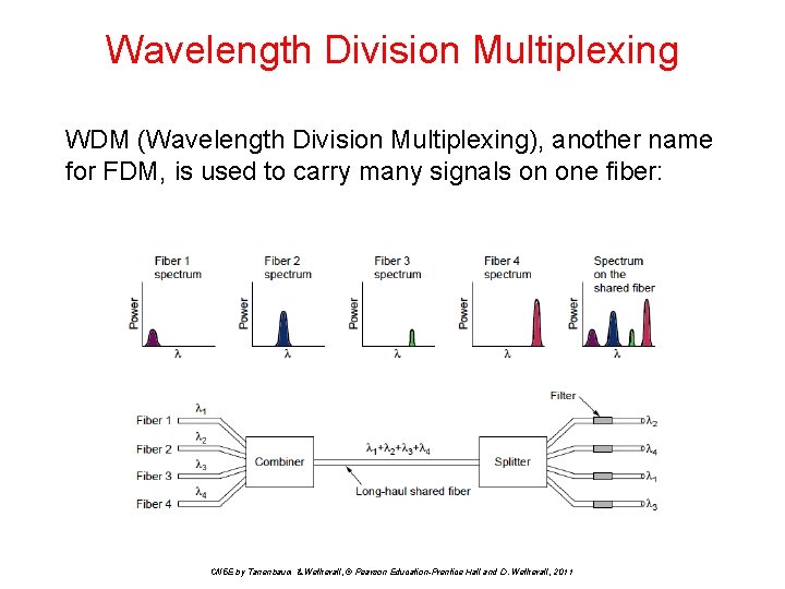
Wavelength Division Multiplexing WDM (Wavelength Division Multiplexing), another name for FDM, is used to carry many signals on one fiber: CN 5 E by Tanenbaum & Wetherall, © Pearson Education-Prentice Hall and D. Wetherall, 2011
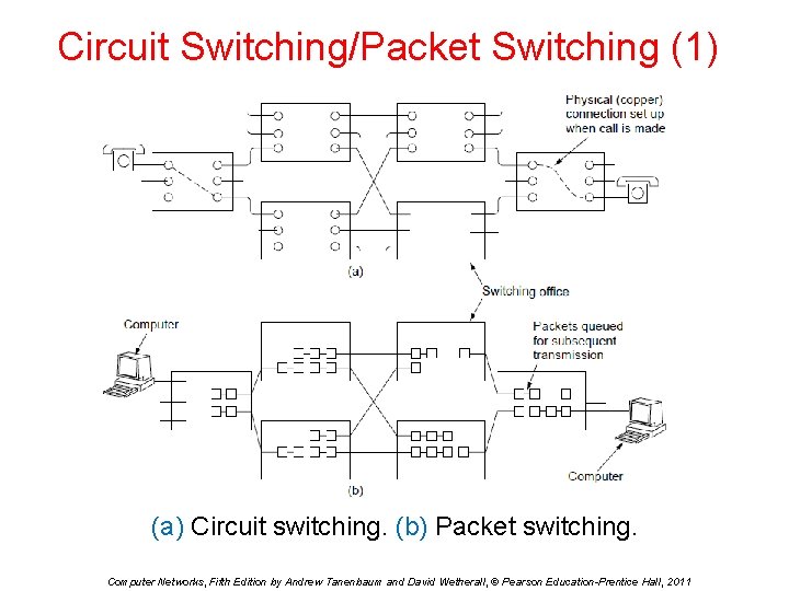
Circuit Switching/Packet Switching (1) (a) Circuit switching. (b) Packet switching. Computer Networks, Fifth Edition by Andrew Tanenbaum and David Wetherall, © Pearson Education-Prentice Hall, 2011
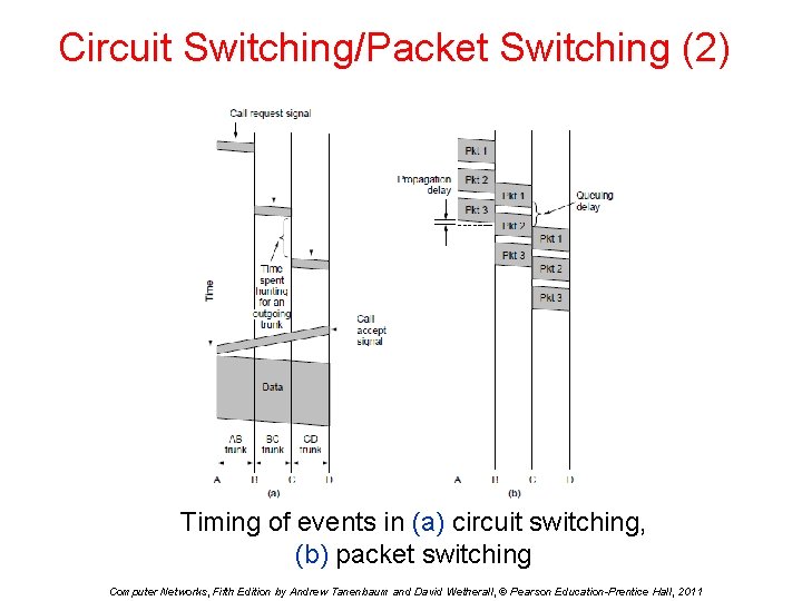
Circuit Switching/Packet Switching (2) Timing of events in (a) circuit switching, (b) packet switching Computer Networks, Fifth Edition by Andrew Tanenbaum and David Wetherall, © Pearson Education-Prentice Hall, 2011
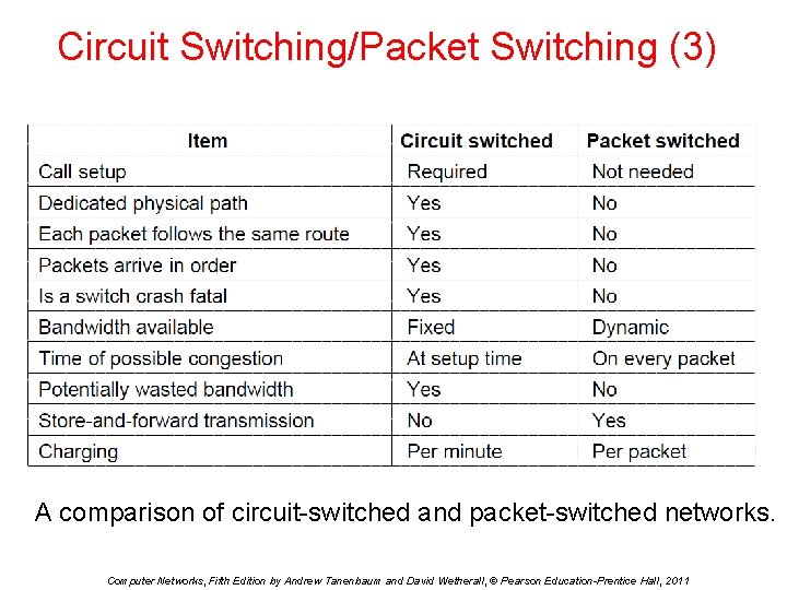
Circuit Switching/Packet Switching (3) A comparison of circuit-switched and packet-switched networks. Computer Networks, Fifth Edition by Andrew Tanenbaum and David Wetherall, © Pearson Education-Prentice Hall, 2011
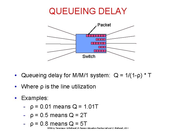
QUEUEING DELAY Packet Switch • Queueing delay for M/M/1 system: Q = 1/(1 -ρ) * T • Where ρ is the line utilization • Examples: - ρ = 0. 01 means Q = 1. 01 T - ρ = 0. 5 means Q = 2 T - ρ = 0. 8 means Q = 5 T CN 5 E by Tanenbaum & Wetherall, © Pearson Education-Prentice Hall and D. Wetherall, 2011
Mobile Telephone System • • • Generations of mobile telephone systems Cellular mobile telephone systems GSM, a 2 G system UMTS, a 3 G system 4 G LTE 4 G CN 5 E by Tanenbaum & Wetherall, © Pearson Education-Prentice Hall and D. Wetherall, 2011
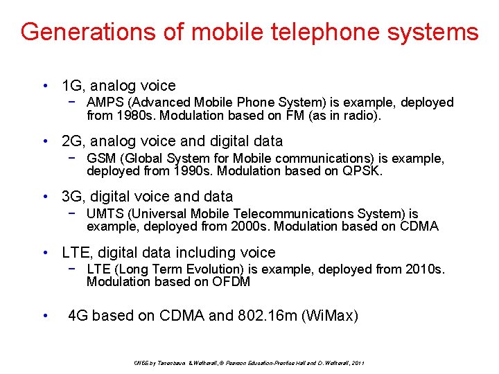
Generations of mobile telephone systems • 1 G, analog voice − AMPS (Advanced Mobile Phone System) is example, deployed from 1980 s. Modulation based on FM (as in radio). • 2 G, analog voice and digital data − GSM (Global System for Mobile communications) is example, deployed from 1990 s. Modulation based on QPSK. • 3 G, digital voice and data − UMTS (Universal Mobile Telecommunications System) is example, deployed from 2000 s. Modulation based on CDMA • LTE, digital data including voice − LTE (Long Term Evolution) is example, deployed from 2010 s. Modulation based on OFDM • 4 G based on CDMA and 802. 16 m (Wi. Max) CN 5 E by Tanenbaum & Wetherall, © Pearson Education-Prentice Hall and D. Wetherall, 2011
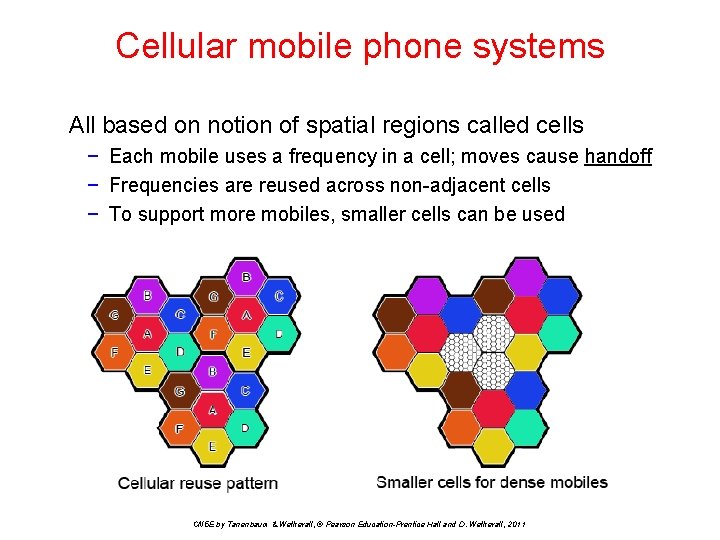
Cellular mobile phone systems All based on notion of spatial regions called cells − Each mobile uses a frequency in a cell; moves cause handoff − Frequencies are reused across non-adjacent cells − To support more mobiles, smaller cells can be used CN 5 E by Tanenbaum & Wetherall, © Pearson Education-Prentice Hall and D. Wetherall, 2011
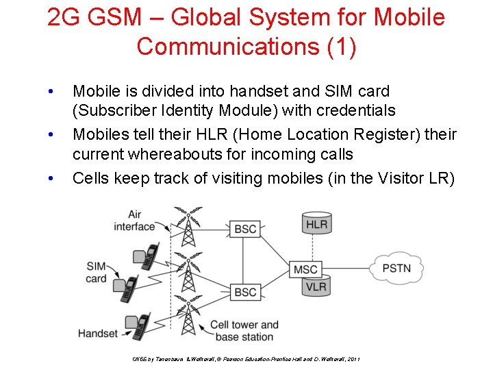
2 G GSM – Global System for Mobile Communications (1) • • • Mobile is divided into handset and SIM card (Subscriber Identity Module) with credentials Mobiles tell their HLR (Home Location Register) their current whereabouts for incoming calls Cells keep track of visiting mobiles (in the Visitor LR) CN 5 E by Tanenbaum & Wetherall, © Pearson Education-Prentice Hall and D. Wetherall, 2011
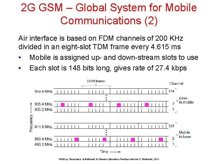
2 G GSM – Global System for Mobile Communications (2) Air interface is based on FDM channels of 200 KHz divided in an eight-slot TDM frame every 4. 615 ms • Mobile is assigned up- and down-stream slots to use • Each slot is 148 bits long, gives rate of 27. 4 kbps CN 5 E by Tanenbaum & Wetherall, © Pearson Education-Prentice Hall and D. Wetherall, 2011
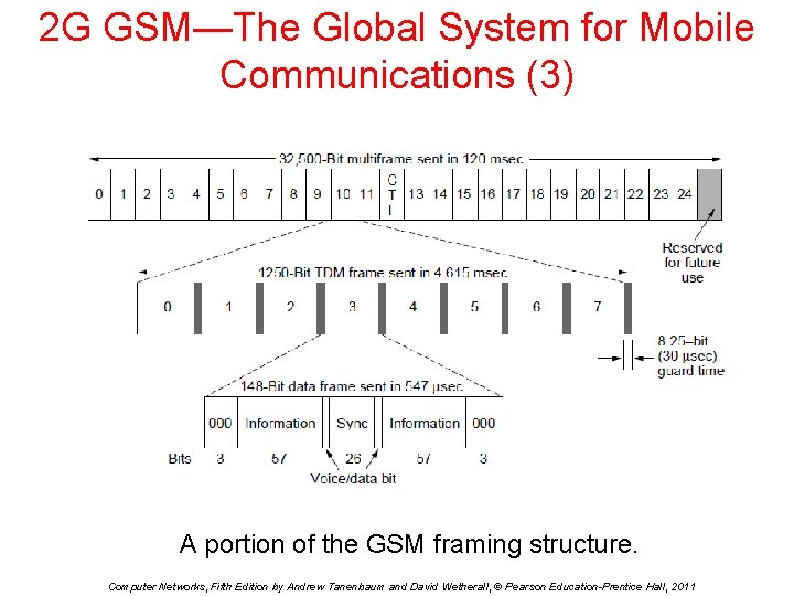
2 G GSM—The Global System for Mobile Communications (3) A portion of the GSM framing structure. Computer Networks, Fifth Edition by Andrew Tanenbaum and David Wetherall, © Pearson Education-Prentice Hall, 2011
Goals for UMTS (3 G) Basic services desired • High-quality voice transmission. • Messaging (replacing email, fax, SMS, chat). • Multimedia (music, videos, films, television). • Internet access (Web surfing, incl. audio, video). Computer Networks, Fifth Edition by Andrew Tanenbaum and David Wetherall, © Pearson Education-Prentice Hall, 2011
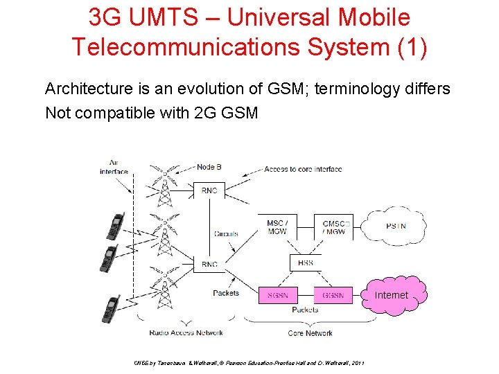
3 G UMTS – Universal Mobile Telecommunications System (1) Architecture is an evolution of GSM; terminology differs Not compatible with 2 G GSM Internet CN 5 E by Tanenbaum & Wetherall, © Pearson Education-Prentice Hall and D. Wetherall, 2011
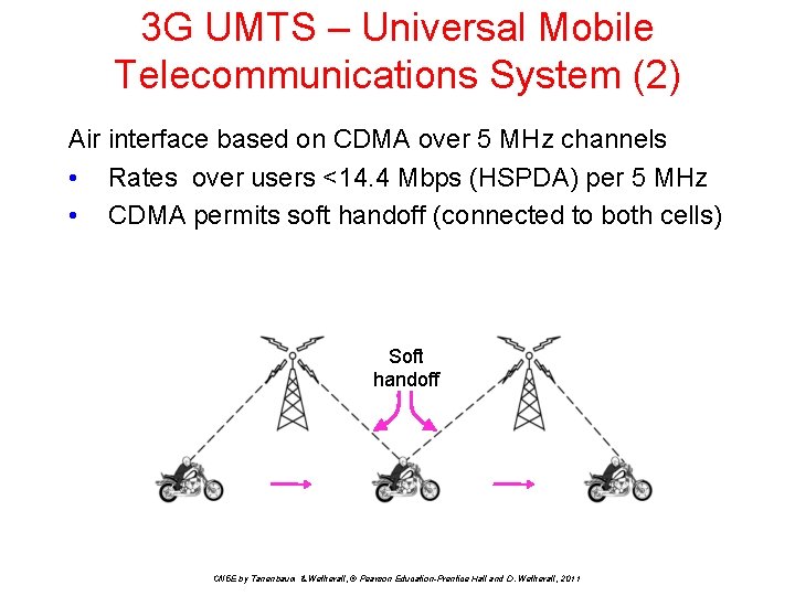
3 G UMTS – Universal Mobile Telecommunications System (2) Air interface based on CDMA over 5 MHz channels • Rates over users <14. 4 Mbps (HSPDA) per 5 MHz • CDMA permits soft handoff (connected to both cells) Soft handoff CN 5 E by Tanenbaum & Wetherall, © Pearson Education-Prentice Hall and D. Wetherall, 2011
4 G • ITU defined spec in 2008, before the technology existed • ITU can’t enforce what carriers do or call their services • Pure IPv 6 packet switching, no circuit switching • No voice (except as Vo. IP) • 1 Gbps for stationary user, 100 Mbps for moving user • Uses carrier aggregation (multiple bands together) • Uses OFDMA (Orthogonal Freq. Div. Mux Access) CN 5 E by Tanenbaum & Wetherall, © Pearson Education-Prentice Hall and D. Wetherall, 2011
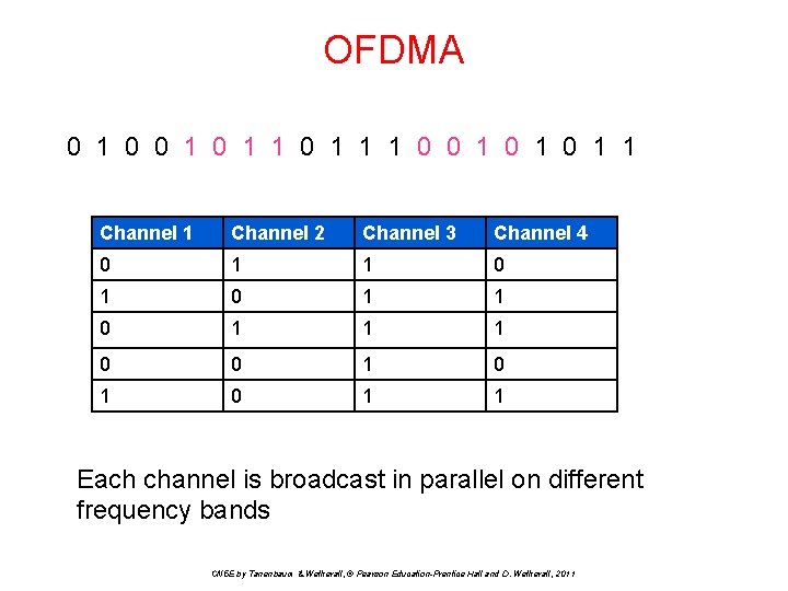
OFDMA 0 1 0 1 1 1 0 0 1 0 1 1 Channel 2 Channel 3 Channel 4 0 1 1 1 0 0 1 0 1 1 Each channel is broadcast in parallel on different frequency bands CN 5 E by Tanenbaum & Wetherall, © Pearson Education-Prentice Hall and D. Wetherall, 2011
Cable Television • • Internet over cable Spectrum allocation Cable modems ADSL vs. cable CN 5 E by Tanenbaum & Wetherall, © Pearson Education-Prentice Hall and D. Wetherall, 2011
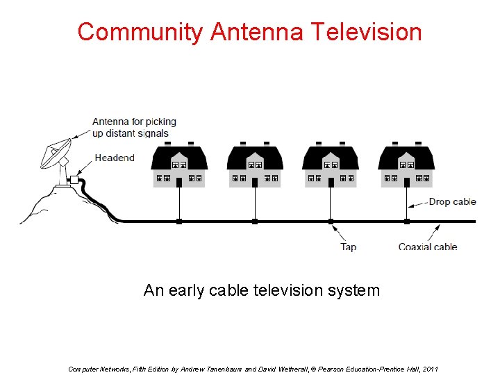
Community Antenna Television An early cable television system Computer Networks, Fifth Edition by Andrew Tanenbaum and David Wetherall, © Pearson Education-Prentice Hall, 2011
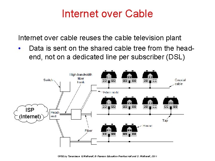
Internet over Cable Internet over cable reuses the cable television plant • Data is sent on the shared cable tree from the headend, not on a dedicated line per subscriber (DSL) ISP (Internet) CN 5 E by Tanenbaum & Wetherall, © Pearson Education-Prentice Hall and D. Wetherall, 2011
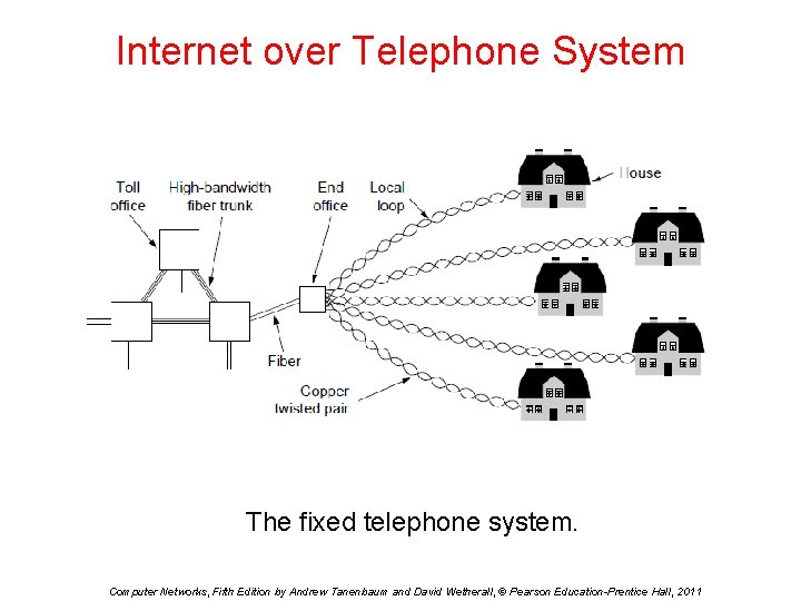
Internet over Telephone System The fixed telephone system. Computer Networks, Fifth Edition by Andrew Tanenbaum and David Wetherall, © Pearson Education-Prentice Hall, 2011
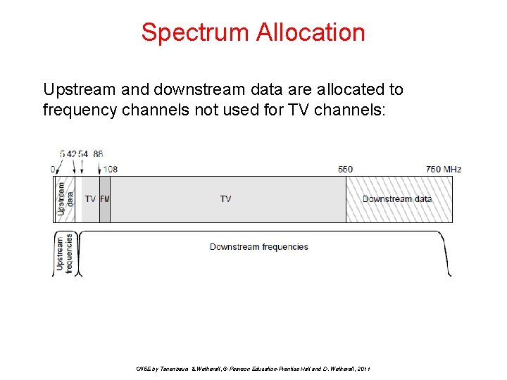
Spectrum Allocation Upstream and downstream data are allocated to frequency channels not used for TV channels: CN 5 E by Tanenbaum & Wetherall, © Pearson Education-Prentice Hall and D. Wetherall, 2011
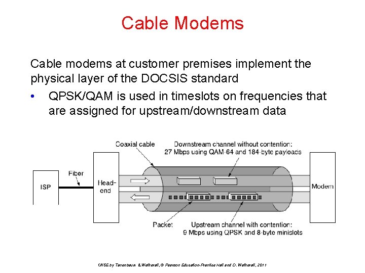
Cable Modems Cable modems at customer premises implement the physical layer of the DOCSIS standard • QPSK/QAM is used in timeslots on frequencies that are assigned for upstream/downstream data CN 5 E by Tanenbaum & Wetherall, © Pearson Education-Prentice Hall and D. Wetherall, 2011
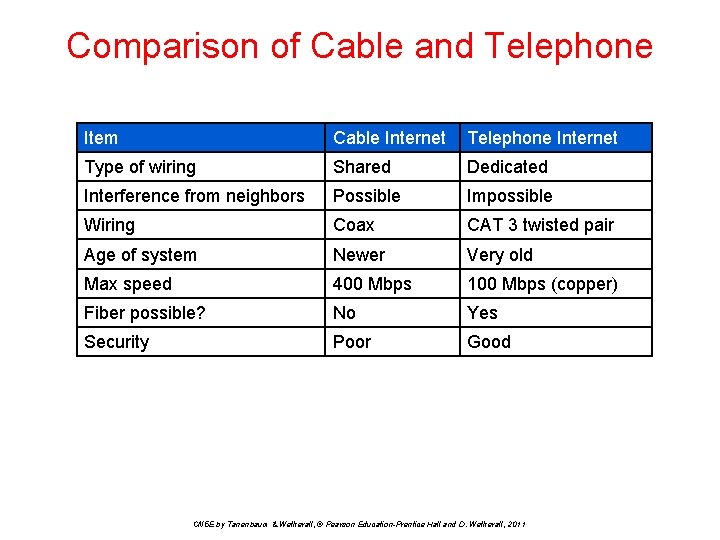
Comparison of Cable and Telephone Item Cable Internet Telephone Internet Type of wiring Shared Dedicated Interference from neighbors Possible Impossible Wiring Coax CAT 3 twisted pair Age of system Newer Very old Max speed 400 Mbps 100 Mbps (copper) Fiber possible? No Yes Security Poor Good CN 5 E by Tanenbaum & Wetherall, © Pearson Education-Prentice Hall and D. Wetherall, 2011
End Chapter 2 CN 5 E by Tanenbaum & Wetherall, © Pearson Education-Prentice Hall and D. Wetherall, 2011

CN 5 E by Tanenbaum & Wetherall, © Pearson Education-Prentice Hall and D. Wetherall, 2011
- Slides: 97