The Optical Fiber and Light Wave Propagation The

The Optical Fiber and Light Wave Propagation

The Optical Fiber • Fiber optic cable functions as a ”light guide, ” guiding the light from one end to the other end. • Fiber categories based on propagation: – Single Mode Fiber (SMF) – Multimode Fiber (MMF) • Categories based on refractive index profile – Step Index Fiber (SIF) – Graded Index Fiber (GIF)

Step Index Fiber n 1 n 2 n 1>n 2 • Uniform ref. index of n 1 (1. 44 < n 1 < 1. 46) within the core and a lower ref. index n 2 in the cladding. • The core and cladding radii are a and b. Typically 2 a/2 b are 8/125, 50/125, 62. 5/125, 85/125, or 100/140 µm. • SIF is generally made by doping high-purity fused silica glass (Si. O 2) with different concentrations of materials like titanium, germanium, or boron.

Different Light Wave Theories • Different theories explain light behaviour • We will first use ray theory to understand light propagation in multimode fibres • Then use electromagnetic wave theory to understand propagation in single mode fibres • Quantum theory is useful to learn photo detection and emission phenomena

Refraction and Reflection When Φ 2 = 90, Φ 1 = Φc is the Snell’s Law: n 1 Sin Φ 1 = n 2 Sin Φ 2 Critical Angle Φc=Sin-1(n 2/n 1 )

Step Index Multimode Fiber

Ray description of different fibers

Single Mode Step Index Fiber Only one propagation mode is allowed in a given wavelength. This is achieved by very small core diameter (8 -10 µm) SMF offers highest bit rate, most widely used in telecom

Step Index Multimode Fiber • Guided light propagation can be explained by ray optics • When the incident angle is smaller the acceptance angle, light will propagate via TIR • Large number of modes possible • Each mode travels at a different velocity Modal Dispersion • Used in short links, mostly with LED sources

Graded Index Multimode Fiber • Core refractive index gradually changes towards the cladding • The light ray gradually bends and the TIR happens at different points • The rays that travel longer distance also travel faster • Offer less modal dispersion compared to Step Index MMF

Step and Graded Index Fibers

Effects of Dispersion and Attenuation

Dispersion for Digital Signals

Modal Dispersion

Major Dispersions in Fiber • Modal Dispersion: Different modes travel at different velocities, exist only in multimode fibers • This was the major problem in first generation systems • Modal dispersion was alleviated with single mode fiber – Still the problem was not fully solved

Dispersion in SMF • Material Dispersion: Since n is a function of wavelength, different wavelengths travel at slightly different velocities. This exists in both multimode and single mode fibers. • Waveguide Dispersion: Signal in the cladding travels with a different velocity than the signal in the core. This phenomenon is significant in single mode conditions. Group Velocity (Chromatic) Dispersion = Material Disp. + Waveguide Disp.

Group Velocity Dispersion

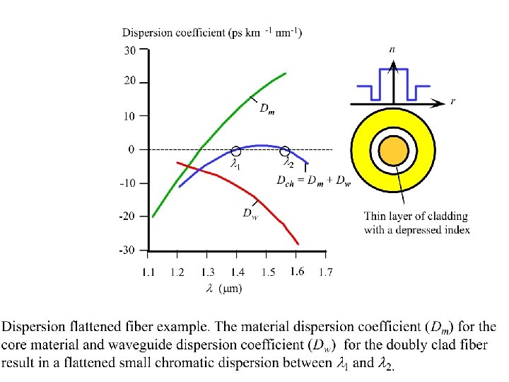
Modifying Chromatic Dispersion GVD = Material Disp. + Waveguide dispersion • Material dispersion depends on the material properties and difficult to alter • Waveguide dispersion depends on fiber dimensions and refractive index profile. These can be altered to get: – 1300 nm optimized fiber – Dispersion Shifted Fiber (DSF) – Dispersion Flattened Fiber (DFF)

Material and Waveguide Dispersions

Different WG Dispersion Profiles WGD is changed by adjusting fiber profile
 (Low Dispersion throughout) (Zero Disp. At 1550 nm)")
Dispersion Shifting/Flattening (Standard) (Low Dispersion throughout) (Zero Disp. At 1550 nm)

Polarization Mode Dispersion • Since optical fiber has a single axis of anisotropy, differently polarized light travels at slightly different velocity • This results in Polarization Mode Dispersion • PMD is usually small, compared to GVD or Modal dispersion • May become significant if all other dispersion mechanisms are small

X and Y Polarizations A Linear Polarized wave will always have two orthogonal components. These can be called x and y polarization components Each component can be individually handled if polarization sensitive components are used
 Each polarization state has a different velocity PMD")
Polarization Mode Dispersion (PMD) Each polarization state has a different velocity PMD

Total Dispersion For Multi Mode Fibers: (Note for MMF ΔTGVD ~= ΔTmat For Single Mode Fibers: But Group Velocity Disp. Hence, (ΔTpol is usually negligible )

Permissible Bit Rate • As a rule of thumb the permissible total dispersion can be up to 70% of the bit period. Therefore,

Disp. & Attenuation Summary

Fiber Optic Link is a Low Pass Filter for Analog Signals

Attenuation in Fiber Attenuation Coefficient • Silica has lowest attenuation at 1550 nm • Water molecules resonate and give high attenuation around 1400 nm in standard fibers • Attenuation happens because: – Absorption (extrinsic and intrinsic) – Scattering losses (Rayleigh, Raman and Brillouin…) – Bending losses (macro and micro bending)

All Wave Fiber for DWDM Lowest attenuation occurs at 1550 nm for Silica

Attenuation characteristics

Micro-bending losses
- Slides: 33