
The Mu 2 e Experiment Ralf Ehrlich for


- Slides: 31
The Mu 2 e Experiment Ralf Ehrlich for the Mu 2 e Collaboration University of Virginia BLV 2013
Outline • • • Short Overview of Mu 2 e Charged Lepton Flavor Violation The concept behind Mu 2 e Design Summary 4/8/2013 Ralf Ehrlich - University of Virginia 2
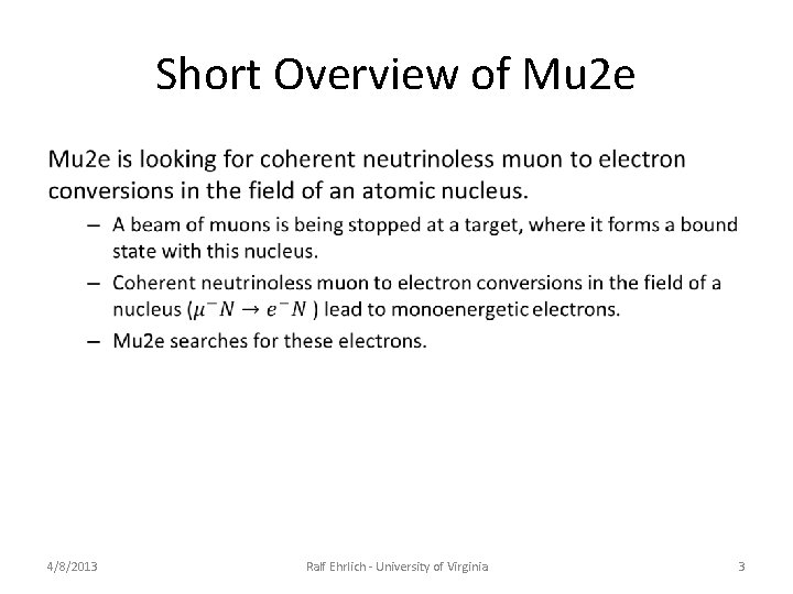
Short Overview of Mu 2 e • 4/8/2013 Ralf Ehrlich - University of Virginia 3
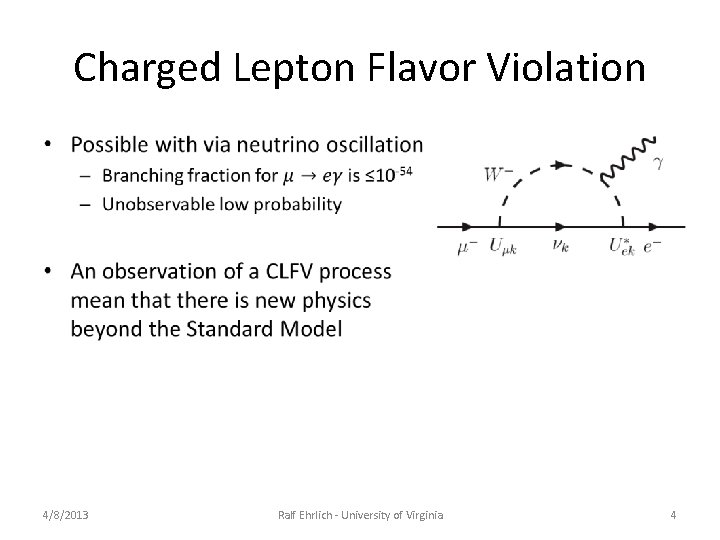
Charged Lepton Flavor Violation • 4/8/2013 Ralf Ehrlich - University of Virginia 4
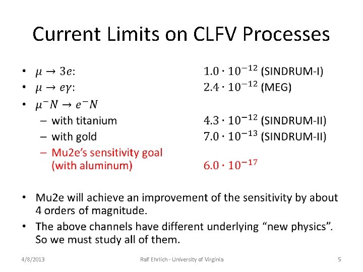
Current Limits on CLFV Processes • 4/8/2013 Ralf Ehrlich - University of Virginia 5
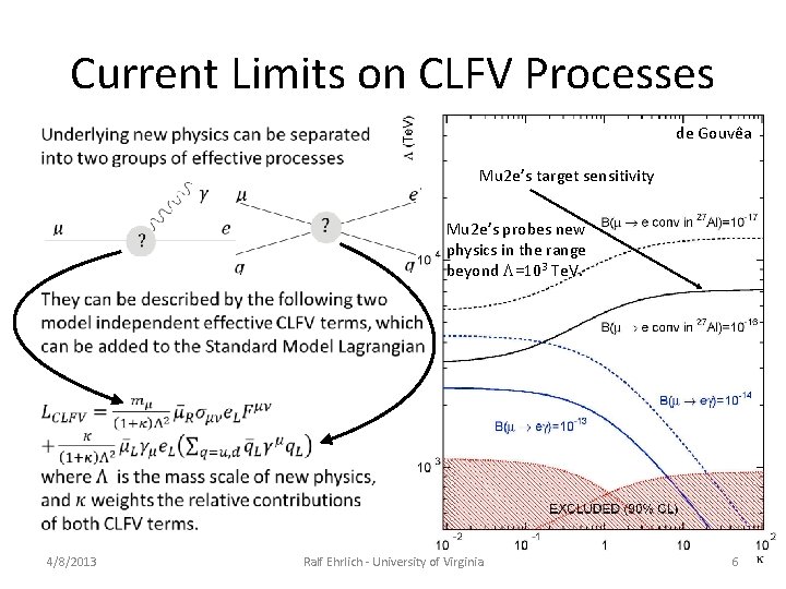
Current Limits on CLFV Processes • de Gouvêa 4/8/2013 Mu 2 e’s target sensitivity Mu 2 e’s probes new physics in the range beyond L=103 Te. V. Ralf Ehrlich - University of Virginia 6
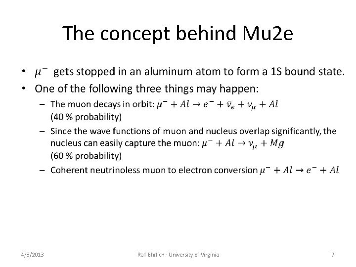
The concept behind Mu 2 e • 4/8/2013 Ralf Ehrlich - University of Virginia 7
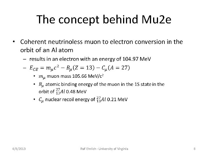
The concept behind Mu 2 e • 4/8/2013 Ralf Ehrlich - University of Virginia 8
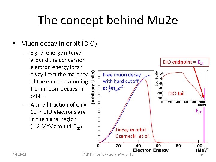
The concept behind Mu 2 e • Muon decay in orbit (DIO) – Signal energy interval around the conversion electron energy is far away from the majority of the electrons coming from muon decays in orbit. – A small fraction of only 10 -17 DIO electrons are in the signal region (1. 2 Me. V around ECE). 4/8/2013 DIO endpoint = ECE DIO tail ECE Decay in orbit Czarnecki et al. Ralf Ehrlich - University of Virginia 9
The concept behind Mu 2 e • 4/8/2013 Ralf Ehrlich - University of Virginia 10
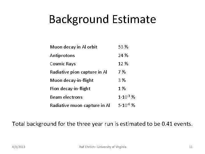
Background Estimate Muon decay in Al orbit 53 % Antiprotons 24 % Cosmic Rays 12 % Radiative pion capture in Al 7 % Muon decay-in-flight 3 % Pion decay-in-flight 1 % Beam electrons 1· 10 -3 % Radiative muon capture in Al 5· 10 -6 % Total background for the three year run is estimated to be 0. 41 events. 4/8/2013 Ralf Ehrlich - University of Virginia 11
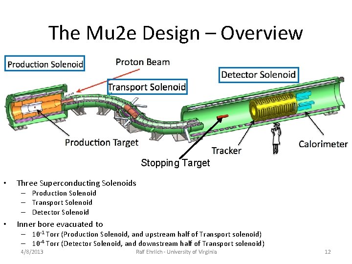
The Mu 2 e Design – Overview Stopping Target • Three Superconducting Solenoids – Production Solenoid – Transport Solenoid – Detector Solenoid • Inner bore evacuated to – 10 -1 Torr (Production Solenoid, and upstream half of Transport solenoid) – 10 -4 Torr (Detector Solenoid, and downstream half of Transport solenoid) 4/8/2013 Ralf Ehrlich - University of Virginia 12
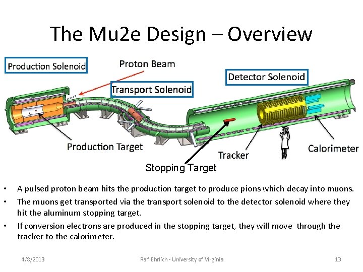
The Mu 2 e Design – Overview Stopping Target • • • A pulsed proton beam hits the production target to produce pions which decay into muons. The muons get transported via the transport solenoid to the detector solenoid where they hit the aluminum stopping target. If conversion electrons are produced in the stopping target, they will move through the tracker to the calorimeter. 4/8/2013 Ralf Ehrlich - University of Virginia 13
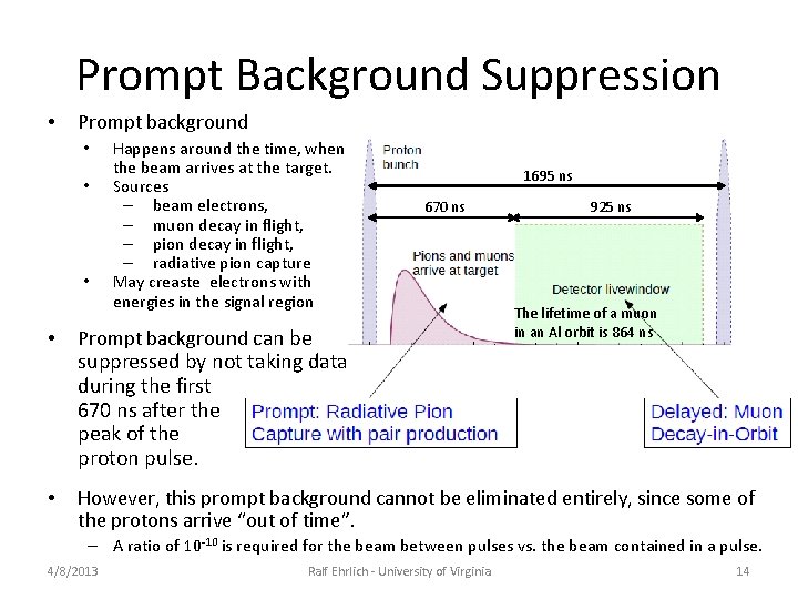
Prompt Background Suppression • Prompt background • • • Happens around the time, when the beam arrives at the target. Sources – beam electrons, – muon decay in flight, – pion decay in flight, – radiative pion capture May creaste electrons with energies in the signal region 1695 ns 670 ns 925 ns The lifetime of a muon in an Al orbit is 864 ns • Prompt background can be • However, this prompt background cannot be eliminated entirely, since some of the protons arrive “out of time”. suppressed by not taking data during the first 670 ns after the peak of the proton pulse. – A ratio of 10 -10 is required for the beam between pulses vs. the beam contained in a pulse. 4/8/2013 Ralf Ehrlich - University of Virginia 14
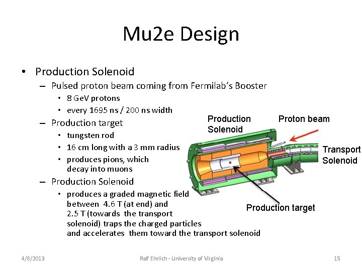
Mu 2 e Design • Production Solenoid – Pulsed proton beam coming from Fermilab’s Booster • 8 Ge. V protons • every 1695 ns / 200 ns width – Production target • tungsten rod • 16 cm long with a 3 mm radius • produces pions, which decay into muons Production Solenoid Proton beam Transport Solenoid – Production Solenoid • produces a graded magnetic field between 4. 6 T (at end) and Production target 2. 5 T (towards the transport solenoid) traps the charged particles and accelerates them toward the transport solenoid 4/8/2013 Ralf Ehrlich - University of Virginia 15
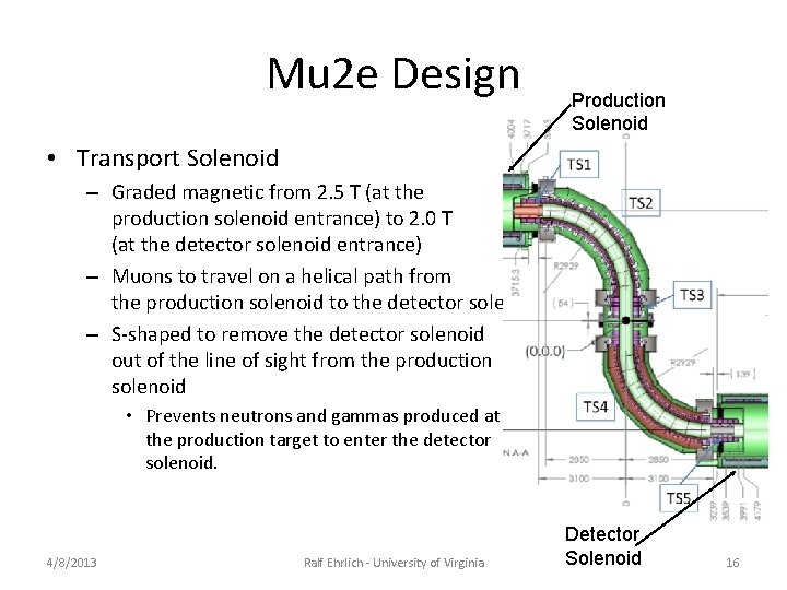
Mu 2 e Design Production Solenoid • Transport Solenoid – Graded magnetic from 2. 5 T (at the production solenoid entrance) to 2. 0 T (at the detector solenoid entrance) – Muons to travel on a helical path from the production solenoid to the detector solenoid – S-shaped to remove the detector solenoid out of the line of sight from the production solenoid • Prevents neutrons and gammas produced at the production target to enter the detector solenoid. 4/8/2013 Ralf Ehrlich - University of Virginia Detector Solenoid 16
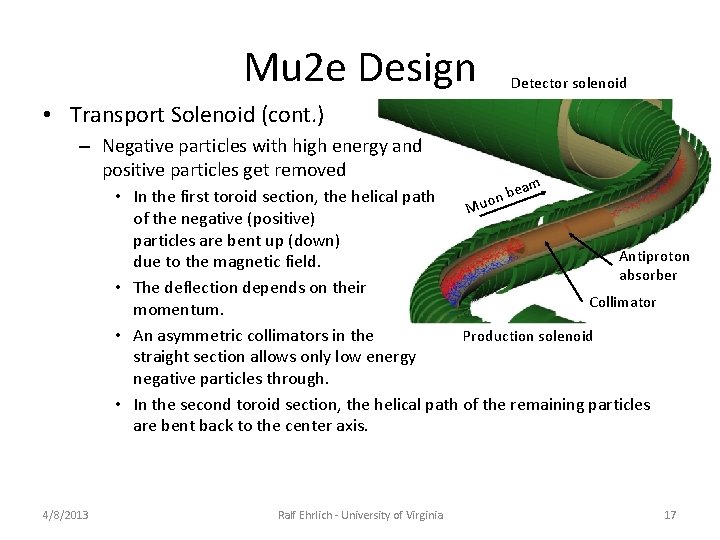
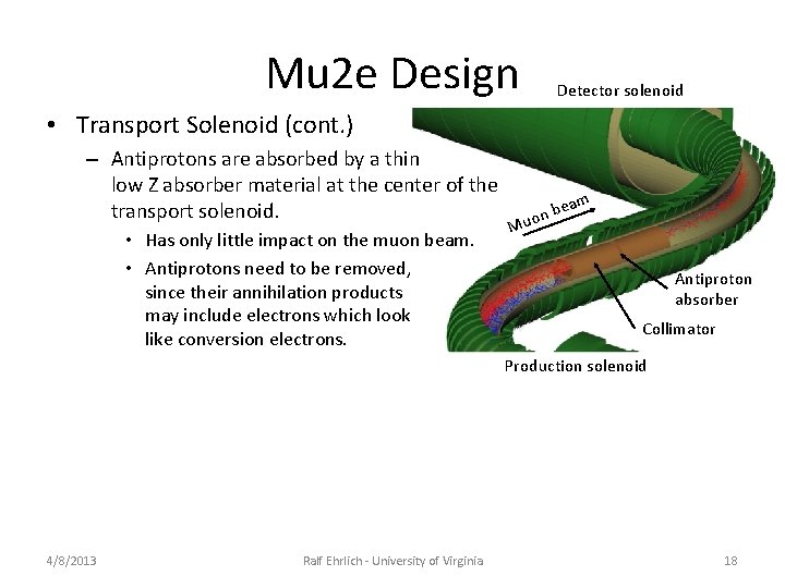
Mu 2 e Design Detector solenoid • Transport Solenoid (cont. ) – Negative particles with high energy and positive particles get removed am be • In the first toroid section, the helical path n o Mu of the negative (positive) particles are bent up (down) Antiproton due to the magnetic field. absorber • The deflection depends on their Collimator momentum. • An asymmetric collimators in the Production solenoid straight section allows only low energy negative particles through. • In the second toroid section, the helical path of the remaining particles are bent back to the center axis. 4/8/2013 Ralf Ehrlich - University of Virginia 17
Mu 2 e Design Detector solenoid • Transport Solenoid (cont. ) – Antiprotons are absorbed by a thin low Z absorber material at the center of the transport solenoid. • Has only little impact on the muon beam. • Antiprotons need to be removed, since their annihilation products may include electrons which look like conversion electrons. am be n o u M Antiproton absorber Collimator Production solenoid 4/8/2013 Ralf Ehrlich - University of Virginia 18
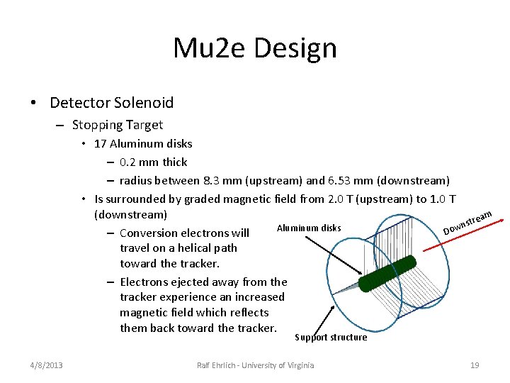
Mu 2 e Design • Detector Solenoid – Stopping Target • 17 Aluminum disks – 0. 2 mm thick – radius between 8. 3 mm (upstream) and 6. 53 mm (downstream) • Is surrounded by graded magnetic field from 2. 0 T (upstream) to 1. 0 T (downstream) m trea s n Aluminum disks Dow – Conversion electrons will travel on a helical path toward the tracker. – Electrons ejected away from the tracker experience an increased magnetic field which reflects them back toward the tracker. Support structure 4/8/2013 Ralf Ehrlich - University of Virginia 19
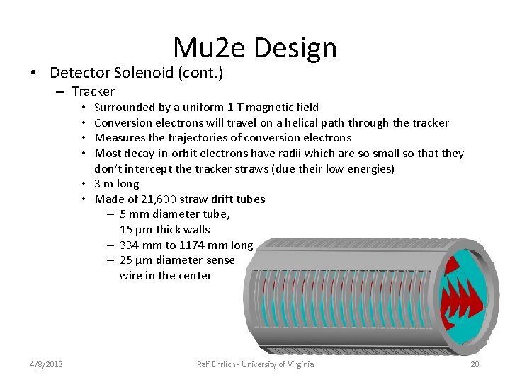
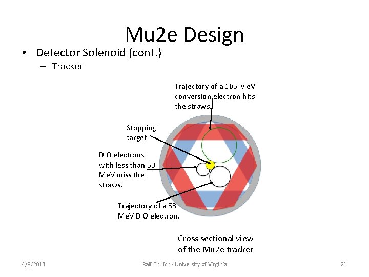
Mu 2 e Design • Detector Solenoid (cont. ) – Tracker Surrounded by a uniform 1 T magnetic field Conversion electrons will travel on a helical path through the tracker Measures the trajectories of conversion electrons Most decay-in-orbit electrons have radii which are so small so that they don’t intercept the tracker straws (due their low energies) • 3 m long • Made of 21, 600 straw drift tubes – 5 mm diameter tube, 15 µm thick walls – 334 mm to 1174 mm long – 25 µm diameter sense wire in the center • • 4/8/2013 Ralf Ehrlich - University of Virginia 20
Mu 2 e Design • Detector Solenoid (cont. ) – Tracker Trajectory of a 105 Me. V conversion electron hits the straws. Stopping target DIO electrons with less than 53 Me. V miss the straws. Trajectory of a 53 Me. V DIO electron. Cross sectional view of the Mu 2 e tracker 4/8/2013 Ralf Ehrlich - University of Virginia 21
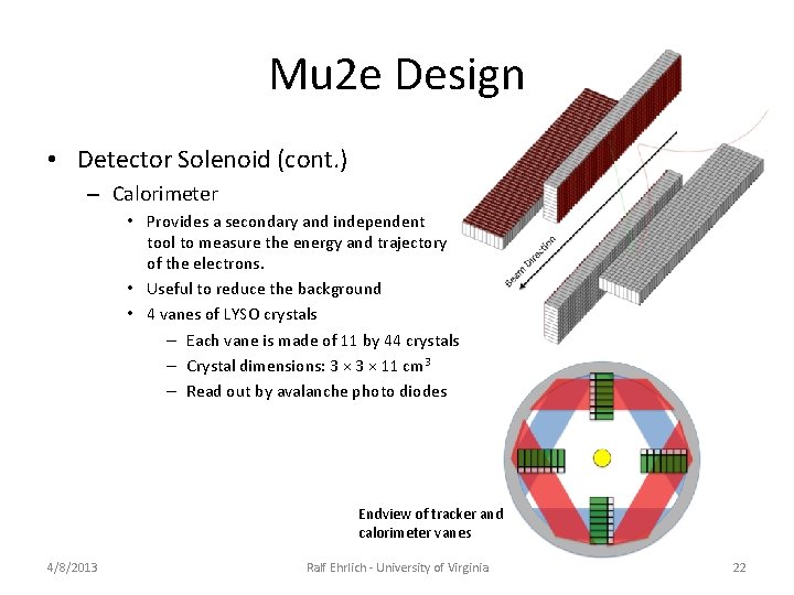
Mu 2 e Design • Detector Solenoid (cont. ) – Calorimeter • Provides a secondary and independent tool to measure the energy and trajectory of the electrons. • Useful to reduce the background • 4 vanes of LYSO crystals – Each vane is made of 11 by 44 crystals – Crystal dimensions: 3 × 11 cm 3 – Read out by avalanche photo diodes Endview of tracker and calorimeter vanes 4/8/2013 Ralf Ehrlich - University of Virginia 22
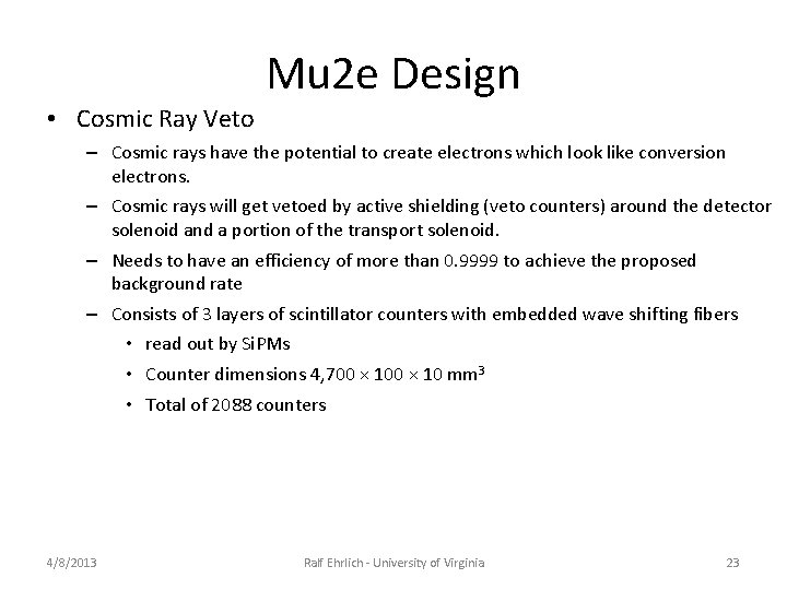
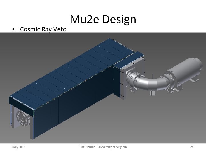
Mu 2 e Design • Cosmic Ray Veto – Cosmic rays have the potential to create electrons which look like conversion electrons. – Cosmic rays will get vetoed by active shielding (veto counters) around the detector solenoid and a portion of the transport solenoid. – Needs to have an efficiency of more than 0. 9999 to achieve the proposed background rate – Consists of 3 layers of scintillator counters with embedded wave shifting fibers • read out by Si. PMs • Counter dimensions 4, 700 × 10 mm 3 • Total of 2088 counters 4/8/2013 Ralf Ehrlich - University of Virginia 23
• Cosmic Ray Veto 4/8/2013 Mu 2 e Design Ralf Ehrlich - University of Virginia 24
Status • Currently in the prototype stage • Data taking expected to begin in 2019 4/8/2013 Ralf Ehrlich - University of Virginia 25
• • • • • • • The Mu 2 e collaboration Boston University Brookhaven National Laboratory California Institute of Technology City University of New York Duke University Fermi National Accelerator Laboratory Institute for Nuclear Research, Moscow, Russia Instituto Nazionale di Fisica Nucleare Lecce and Università del Salento Instituto Nazionale di Fisica Nucleare Lecce and Università Marconi Roma Instituto Nazionale di Fisica Nucleare Pisa Joint Institute for Nuclear Research, Dubna Laboratori Nazionali di Frascati Lewis University Muons, Inc. Northern Illinois University Northwestern University Pacific Northwestern National Laboratory Rice University Universita di Udine and INFN Trieste/Udine University of California, Berkeley University of California, Irvine University of Houston University of Illinois, Urbana-Champaign University of Massachusetts, Amherst University of Virginia University of Washington 4/8/2013 Ralf Ehrlich - University of Virginia 26
Summary 4/8/2013 Ralf Ehrlich - University of Virginia 27
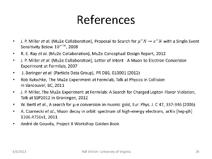
References • 4/8/2013 Ralf Ehrlich - University of Virginia 28
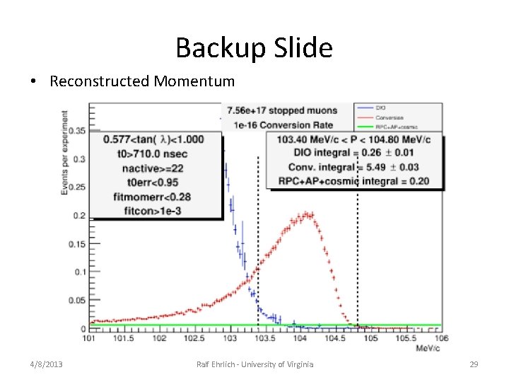
Backup Slide • Reconstructed Momentum 4/8/2013 Ralf Ehrlich - University of Virginia 29
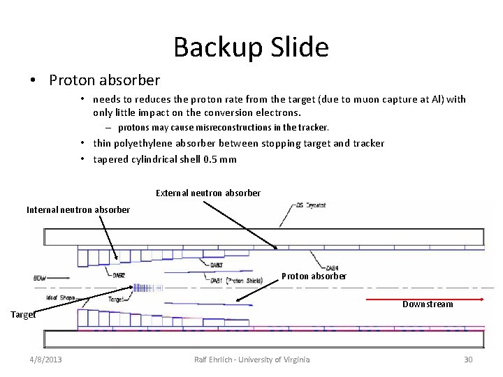
Backup Slide • Proton absorber • needs to reduces the proton rate from the target (due to muon capture at Al) with only little impact on the conversion electrons. – protons may cause misreconstructions in the tracker. • thin polyethylene absorber between stopping target and tracker • tapered cylindrical shell 0. 5 mm External neutron absorber Internal neutron absorber Proton absorber Downstream Target 4/8/2013 Ralf Ehrlich - University of Virginia 30
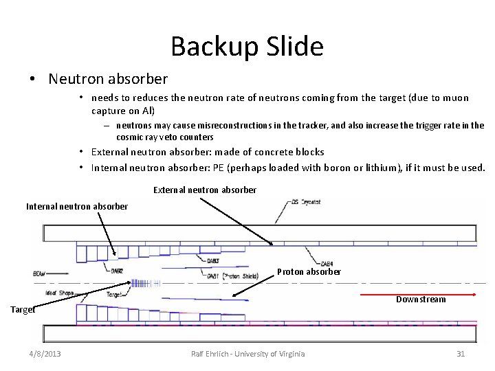
Backup Slide • Neutron absorber • needs to reduces the neutron rate of neutrons coming from the target (due to muon capture on Al) – neutrons may cause misreconstructions in the tracker, and also increase the trigger rate in the cosmic ray veto counters • External neutron absorber: made of concrete blocks • Internal neutron absorber: PE (perhaps loaded with boron or lithium), if it must be used. External neutron absorber Internal neutron absorber Proton absorber Downstream Target 4/8/2013 Ralf Ehrlich - University of Virginia 31