
The LHC Machine Jrg Wenninger CERN Beams Department
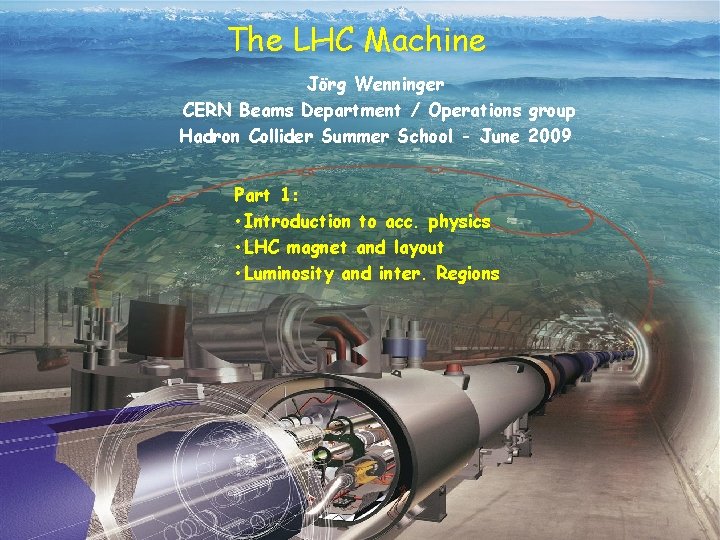
The LHC Machine Jörg Wenninger CERN Beams Department / Operations group Hadron Collider Summer School - June 2009 Part 1: • Introduction to acc. physics • LHC magnet and layout • Luminosity and inter. Regions 1
Outline • The LHC challenges • Introduction to magnets and particle focusing • LHC magnets and arc layout Part 1 • LHC luminosity and interaction regions • Machine protection • Incident 19 th Sept. 2008 Part 2 • LHC commissioning and operation 2
LHC History 1982 : First studies for the LHC project 1983 : Z 0/W discovered at SPS proton antiproton collider (Sppbar. S) 1989 : Start of LEP operation (Z/W boson-factory) 1994 : Approval of the LHC by the CERN Council 1996 : Final decision to start the LHC construction 2000 : Last year of LEP operation above 100 Ge. V 2002 : LEP equipment removed 2003 : Start of LHC installation 2005 : Start of LHC hardware commissioning 2008 : Start of (short) beam commissioning Powering incident on 19 th Sept. 2009 : Repair, re-commissioning and beam commissioning 3
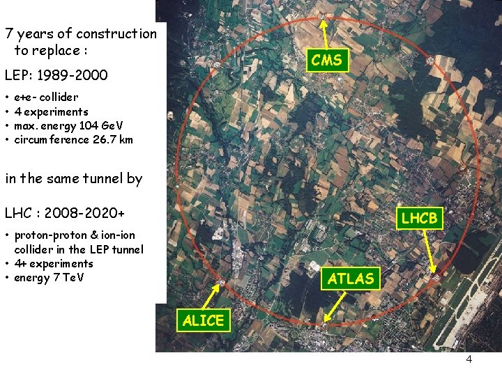
7 years of construction to replace : CMS LEP: 1989 -2000 • • e+e- collider 4 experiments max. energy 104 Ge. V circumference 26. 7 km in the same tunnel by LHC : 2008 -2020+ LHCB • proton-proton & ion-ion collider in the LEP tunnel • 4+ experiments • energy 7 Te. V ATLAS ALICE 4
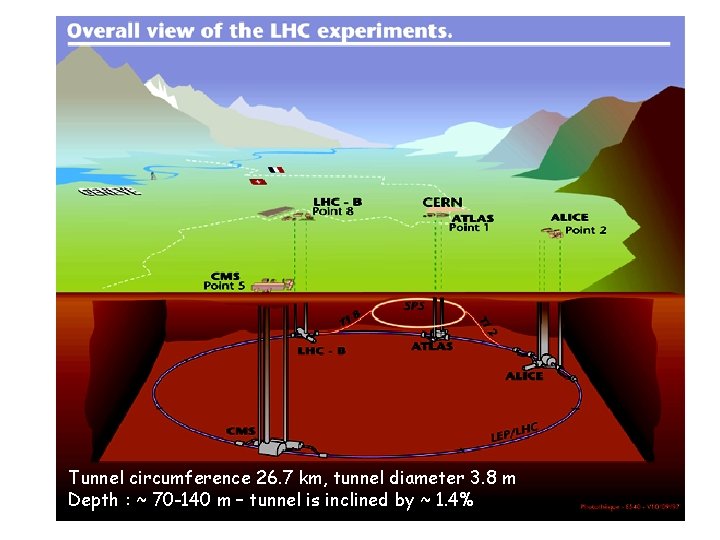
Tunnel circumference 26. 7 km, tunnel diameter 3. 8 m Depth : ~ 70 -140 m – tunnel is inclined by ~ 1. 4% 5
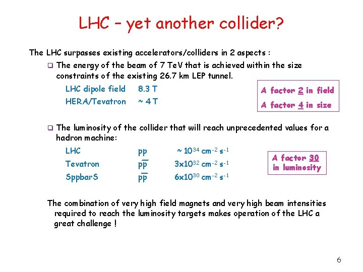
LHC – yet another collider? The LHC surpasses existing accelerators/colliders in 2 aspects : q The energy of the beam of 7 Te. V that is achieved within the size constraints of the existing 26. 7 km LEP tunnel. LHC dipole field 8. 3 T HERA/Tevatron ~4 T A factor 2 in field A factor 4 in size q The luminosity of the collider that will reach unprecedented values for a hadron machine: LHC pp ~ 1034 cm-2 s-1 Tevatron pp 3 x 1032 cm-2 s-1 Sppbar. S pp 6 x 1030 cm-2 s-1 A factor 30 in luminosity The combination of very high field magnets and very high beam intensities required to reach the luminosity targets makes operation of the LHC a great challenge ! 6
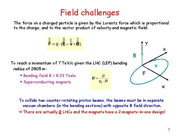
Field challenges The force on a charged particle is given by the Lorentz force which is proportional to the charge, and to the vector product of velocity and magnetic field: y s B To reach a momentum of 7 Te. V/c given the LHC (LEP) bending radius of 2805 m: § Bending field B = 8. 33 Tesla § Superconducting magnets v F x To collide two counter-rotating proton beams, the beams must be in separate vaccum chambers (in the bending sections) with opposite B field direction. There actually 2 LHCs and the magnets have a 2 -magnets-in-one design! 7
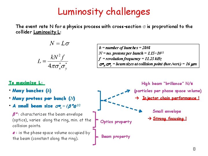
Luminosity challenges The event rate N for a physics process with cross-section s is proprotional to the collider Luminosity L: k = number of bunches = 2808 N = no. protons per bunch = 1. 15× 1011 f = revolution frequency = 11. 25 k. Hz s*x, s*y = beam sizes at collision point (hor. /vert. ) = 16 mm To maximize L: High beam “brillance” N/e • Many bunches (k) • Many protons per bunch (N) • A small beam size s*u = (b *e)1/2 (particles per phase space volume) Injector chain performance ! Small envelope b * : characterizes the beam envelope (optics), varies along the ring, min. at the collision points. e : is the phase space volume occupied by the beam (constant along the ring). Optics property Strong focusing ! Beam property 8
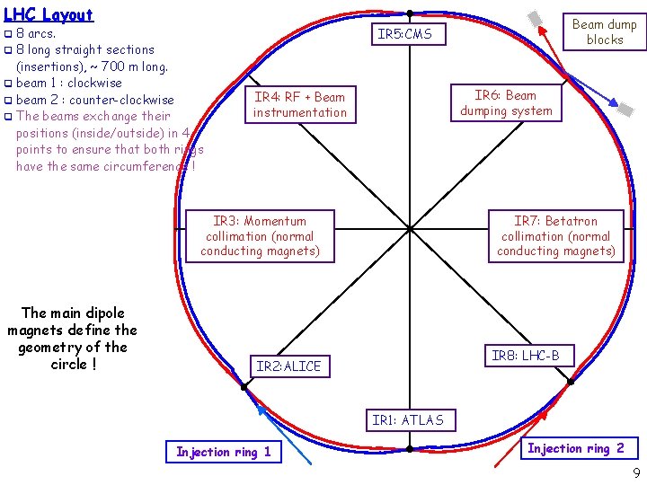
LHC Layout 8 arcs. q 8 long straight sections (insertions), ~ 700 m long. q beam 1 : clockwise q beam 2 : counter-clockwise q The beams exchange their positions (inside/outside) in 4 points to ensure that both rings have the same circumference ! IR 6: Beam dumping system IR 4: RF + Beam instrumentation IR 3: Momentum collimation (normal conducting magnets) The main dipole magnets define the geometry of the circle ! Beam dump blocks IR 5: CMS q IR 7: Betatron collimation (normal conducting magnets) IR 8: LHC-B IR 2: ALICE IR 1: ATLAS Injection ring 1 Injection ring 2 9

LHC and its injectors 5 LHC 4 Beam 1 Beam 2 6 7 3 TI 8 2 TI 2 protons LINACS SPS Booster 8 1 CPS Ions LEIR Linac PSB CPS SPS LHC Top energy/Ge. V Circumference/m 0. 12 30 1. 4 157 26 628 = 4 PSB 450 6’ 911 = 11 x PS 7000 26’ 657 = 27/7 x SPS The energy gain/machine of 10 to 20 is typical for the useful range of magnets !!! 10
Basics of Accelerator Physics 11
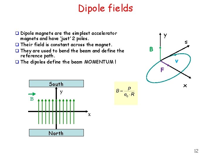
Dipole fields q Dipole magnets are the simplest accelerator magnets and have ‘just’ 2 poles. q Their field is constant across the magnet. q They are used to bend the beam and define the reference path. q The dipoles define the beam MOMENTUM ! y s B v F South y x B x North 12
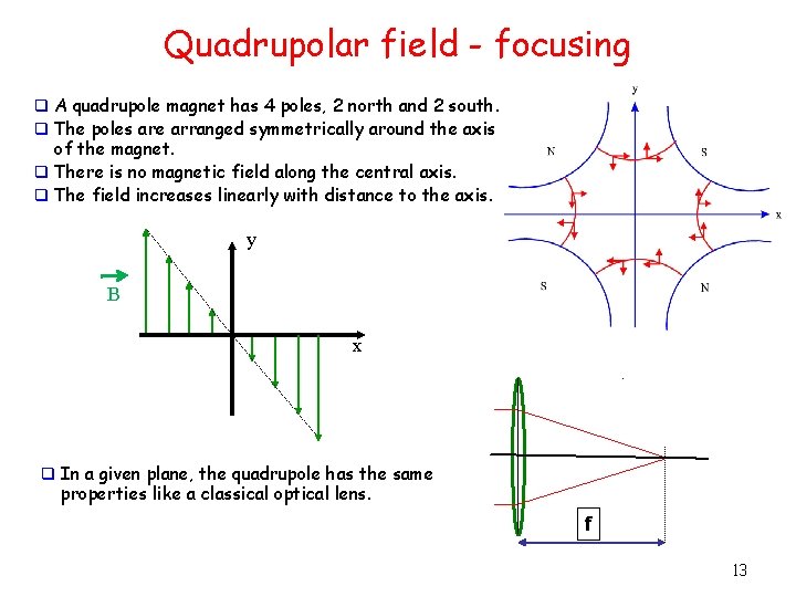
Quadrupolar field - focusing q A quadrupole magnet has 4 poles, 2 north and 2 south. q The poles are arranged symmetrically around the axis of the magnet. q There is no magnetic field along the central axis. q The field increases linearly with distance to the axis. y B x q In a given plane, the quadrupole has the same properties like a classical optical lens. f 13
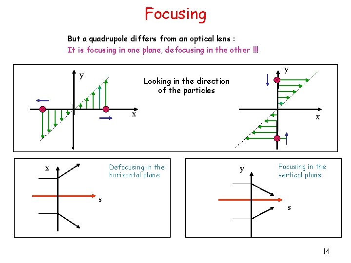
Focusing But a quadrupole differs from an optical lens : It is focusing in one plane, defocusing in the other !!! y y Looking in the direction of the particles x Defocusing in the horizontal plane x s x y Focusing in the vertical plane s 14
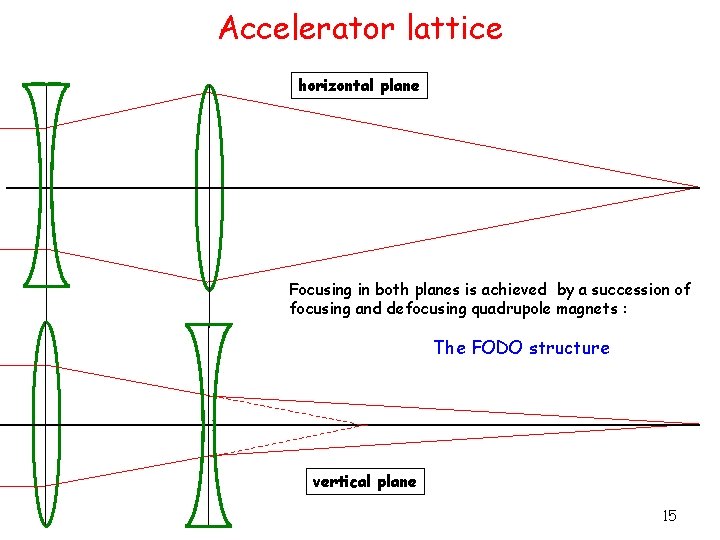
Accelerator lattice horizontal plane Focusing in both planes is achieved by a succession of focusing and defocusing quadrupole magnets : The FODO structure vertical plane 15

LHC arc lattice q Dipole- und Quadrupol magnets – q Sextupole magnets – q Provide a stable trajectory for particles with nominal momentum. Correct the trajectories for off momentum particles (‚chromatic‘ errors). Multipole-corrector magnets – – Sextupole - and decapole corrector magnets at end of dipoles Used to compensate field imperfections if the dipole magnets. To stabilize trajectories for particles at larger amplitudes – beam lifetime ! One rarely talks about the multipole magnets, but they are also essential for the good machine performance ! 16
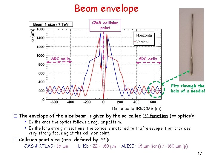
Beam envelope CMS collision point ARC cells Fits through the hole of a needle! q The envelope of the size beam is given by the so-called ‘b’-function ( optics): • In the arcs the optics follows a regular pattern. • In the long straight sections, the optics is matched to the ‘telescope’ that provides very strong focusing at the collision point. q Collision point size (rms, defined by ‘b*’): CMS & ATLAS : 16 m LHCb : 22 – 160 m ALICE : 16 m (ions) / >160 m (p) 17
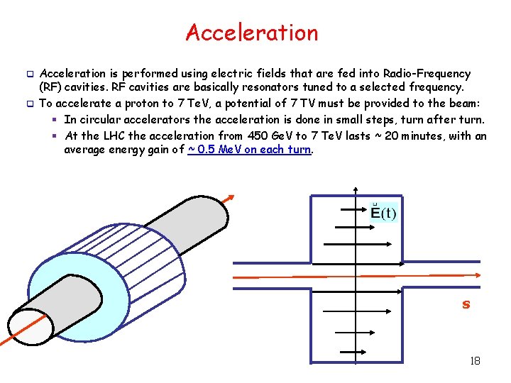
Acceleration is performed using electric fields that are fed into Radio-Frequency (RF) cavities. RF cavities are basically resonators tuned to a selected frequency. q To accelerate a proton to 7 Te. V, a potential of 7 TV must be provided to the beam: § In circular accelerators the acceleration is done in small steps, turn after turn. § At the LHC the acceleration from 450 Ge. V to 7 Te. V lasts ~ 20 minutes, with an average energy gain of ~ 0. 5 Me. V on each turn. q s 18
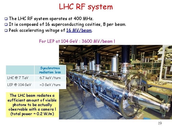
LHC RF system The LHC RF system operates at 400 MHz. q It is composed of 16 superconducting cavities, 8 per beam. q Peak accelerating voltage of 16 MV/beam. q For LEP at 104 Ge. V : 3600 MV/beam ! Synchrotron radiation loss LHC @ 7 Te. V 6. 7 ke. V /turn LEP @ 104 Ge. V ~3 Ge. V /turn The LHC beam radiates a sufficient amount of visible photons to be actually observable with a camera ! (total power ~ 0. 2 W/m) 19
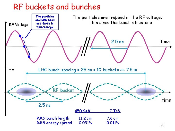
RF buckets and bunches RF Voltage The particles oscillate back and forth in time/energy The particles are trapped in the RF voltage: this gives the bunch structure 2. 5 ns E time LHC bunch spacing = 25 ns = 10 buckets 7. 5 m RF bucket time 2. 5 ns 450 Ge. V RMS bunch length RMS energy spread 11. 2 cm 0. 031% 7 Te. V 7. 6 cm 0. 011% 20
Magnets & Tunnel 21
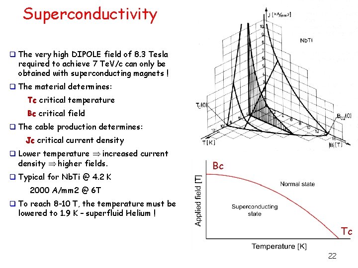
Superconductivity q The very high DIPOLE field of 8. 3 Tesla required to achieve 7 Te. V/c can only be obtained with superconducting magnets ! q The material determines: Tc critical temperature Bc critical field q The cable production determines: Jc critical current density q Lower temperature increased current density higher fields. q Typical for Nb. Ti @ 4. 2 K Bc 2000 A/mm 2 @ 6 T q To reach 8 -10 T, the temperature must be lowered to 1. 9 K – superfluid Helium ! Tc 22
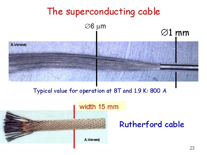
The superconducting cable 6 m 1 mm A. Verweij Typical value for operation at 8 T and 1. 9 K: 800 A width 15 mm Rutherford cable A. Verweij 23
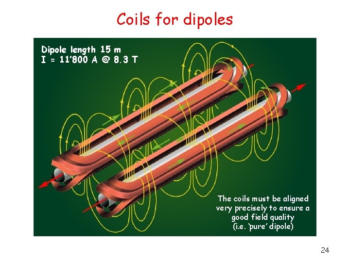
Coils for dipoles Dipole length 15 m I = 11’ 800 A @ 8. 3 T The coils must be aligned very precisely to ensure a good field quality (i. e. ‘pure’ dipole) 24
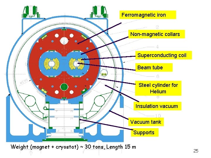
Ferromagnetic iron Non-magnetic collars Superconducting coil Beam tube Steel cylinder for Helium Insulation vacuum Vacuum tank Supports Weight (magnet + cryostat) ~ 30 tons, Length 15 m Rüdiger Schmidt 25 25
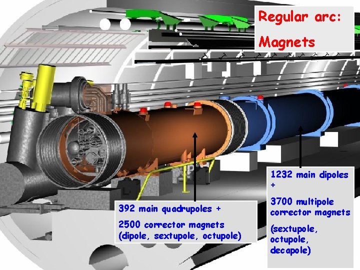
Regular arc: Magnets 1232 main dipoles + 392 main quadrupoles + 2500 corrector magnets (dipole, sextupole, octupole) 3700 multipole corrector magnets (sextupole, octupole, decapole) J. Wenninger - ETHZ - December 2005 26 26
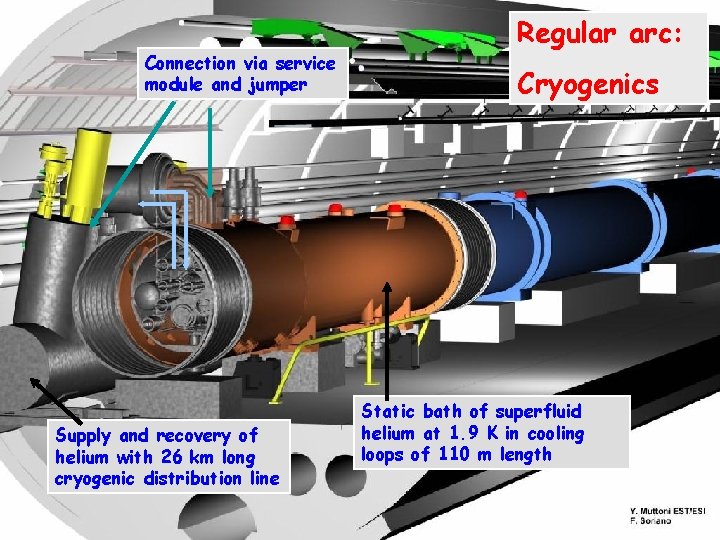
Connection via service module and jumper Supply and recovery of helium with 26 km long cryogenic distribution line Regular arc: Cryogenics Static bath of superfluid helium at 1. 9 K in cooling loops of 110 m length J. Wenninger - ETHZ - December 2005 27 27
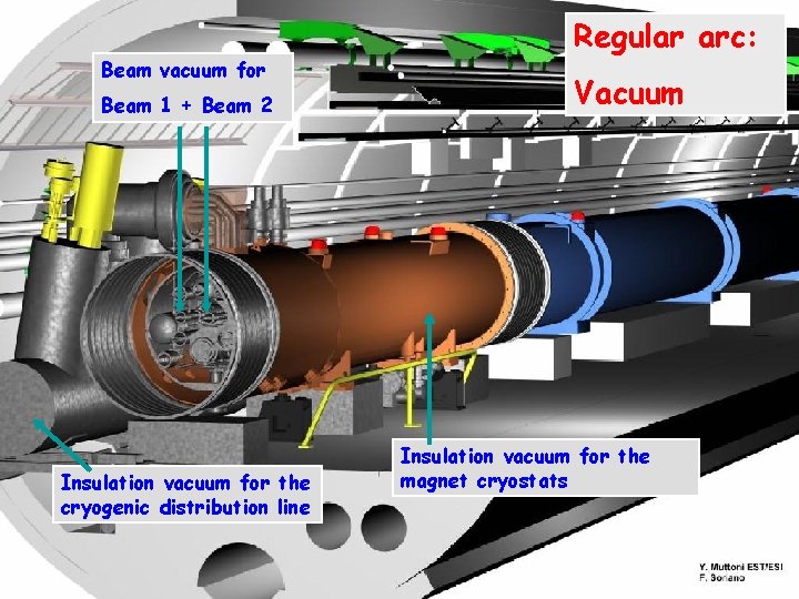
Beam vacuum for Beam 1 + Beam 2 Insulation vacuum for the cryogenic distribution line Regular arc: Vacuum Insulation vacuum for the magnet cryostats J. Wenninger - ETHZ - December 2005 28 28
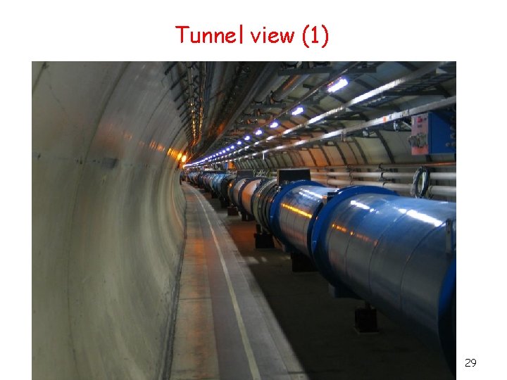
Tunnel view (1) 29
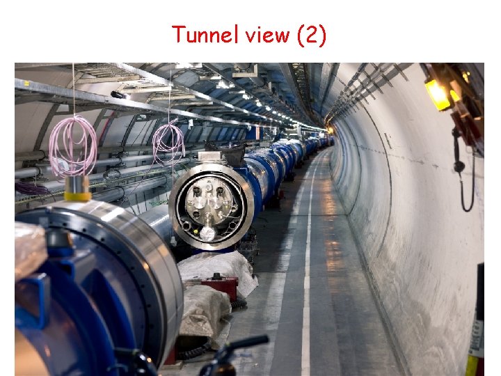
Tunnel view (2) 30
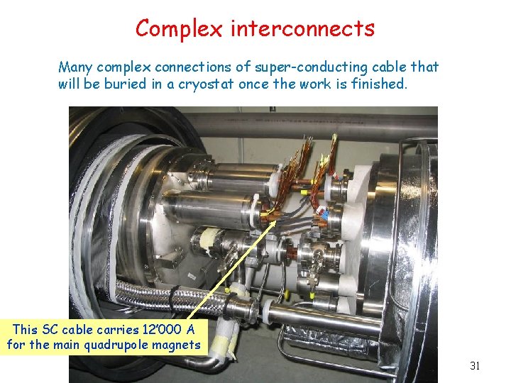
Complex interconnects Many complex connections of super-conducting cable that will be buried in a cryostat once the work is finished. This SC cable carries 12’ 000 A for the main quadrupole magnets CERN visit Mc. Ewen 31
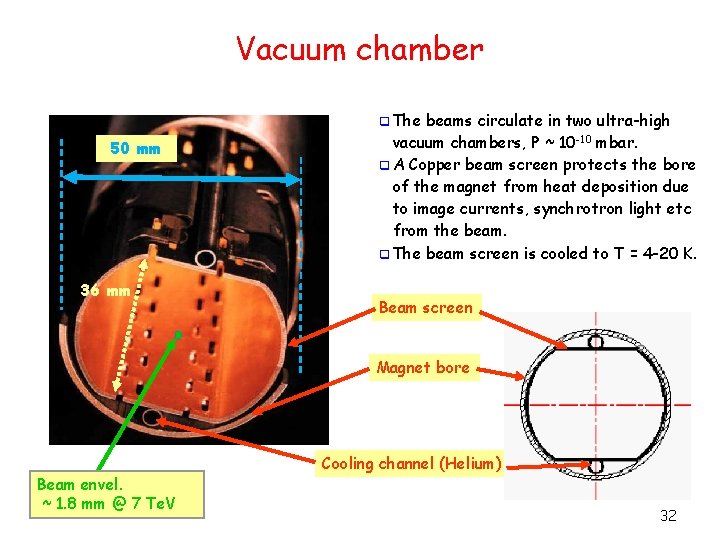
Vacuum chamber q The 50 mm 36 mm beams circulate in two ultra-high vacuum chambers, P ~ 10 -10 mbar. q A Copper beam screen protects the bore of the magnet from heat deposition due to image currents, synchrotron light etc from the beam. q The beam screen is cooled to T = 4 -20 K. Beam screen Magnet bore Beam envel. ~ 1. 8 mm @ 7 Te. V Cooling channel (Helium) 32

Luminosity and Interaction Regions 33
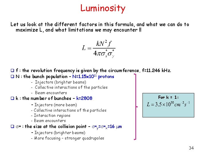
Luminosity Let us look at the different factors in this formula, and what we can do to maximize L, and what limitations we may encounter !! q f : the revolution frequency is given by the circumference, f=11. 246 k. Hz. q N : the bunch population – N=1. 15 x 1011 protons - Injectors (brighter beams) - Collective interactions of the particles - Beam encounters q k : the number of bunches – k=2808 For k = 1: - Injectors (more beam) - Collective interactions of the particles - Interaction regions - Beam encounters q s* : the size at the collision point – s*y=s*x=16 m - Injectors (brighter beams) - More focusing – stronger quadrupoles 34
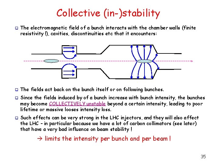
Collective (in-)stability q The electromagnetic field of a bunch interacts with the chamber walls (finite resistivity !), cavities, discontinuities etc that it encounters: q The fields act back on the bunch itself or on following bunches. q Since the fields induced by of a bunch increase with bunch intensity, the bunches may become COLLECTIVELY unstable beyond a certain intensity, leading to poor lifetime or massive looses intensity loss. q Such effects can be very strong in the LHC injectors, and they will also affect the LHC – in particular because we have a lot of carbon collimators (see later) that have a very bad influence on beam stability ! limits the intensity per bunch and per beam ! 35
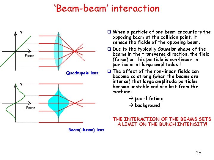
‘Beam-beam’ interaction q When a particle of one beam encounters the Quadrupole lens Beam(-beam) lens opposing beam at the collision point, it senses the fields of the opposing beam. q Due to the typically Gaussian shape of the beams in the transverse direction, the field (force) on this particle is non-linear, in particular at large amplitudes ! q The effect of the non-linear fields can become so strong (when the beams are intense) that large amplitude particles become unstable and are lost from the machine: poor lifetime background THE INTERACTION OF THE BEAMS SETS A LIMIT ON THE BUNCH INTENSITY! 36
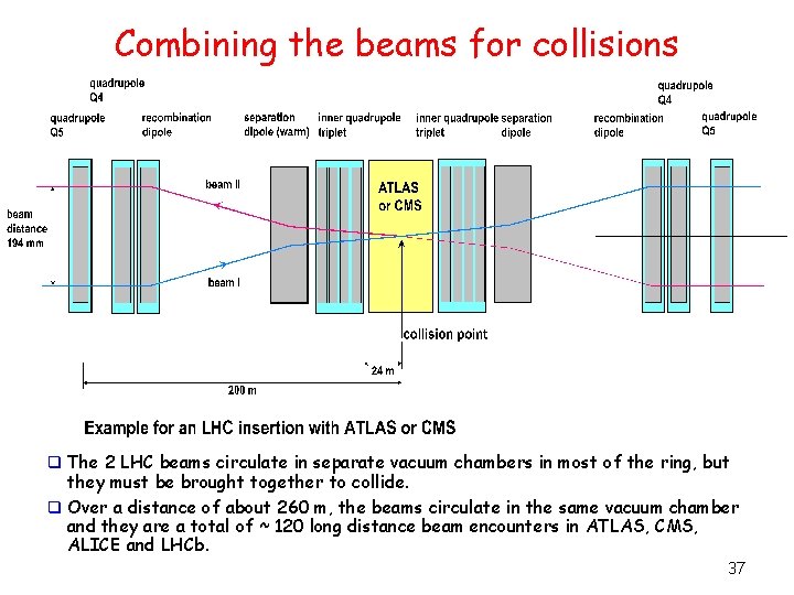
Combining the beams for collisions q The 2 LHC beams circulate in separate vacuum chambers in most of the ring, but they must be brought together to collide. q Over a distance of about 260 m, the beams circulate in the same vacuum chamber and they are a total of ~ 120 long distance beam encounters in ATLAS, CMS, ALICE and LHCb. 37
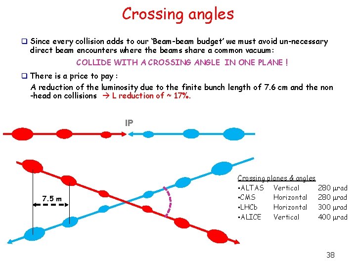
Crossing angles q Since every collision adds to our ‘Beam-beam budget’ we must avoid un-necessary direct beam encounters where the beams share a common vacuum: COLLIDE WITH A CROSSING ANGLE IN ONE PLANE ! q There is a price to pay : A reduction of the luminosity due to the finite bunch length of 7. 6 cm and the non -head on collisions L reduction of ~ 17%. IP 7. 5 m Crossing planes & angles • ALTAS Vertical • CMS Horizontal • LHCb Horizontal • ALICE Vertical 280 rad 300 rad 400 rad 38
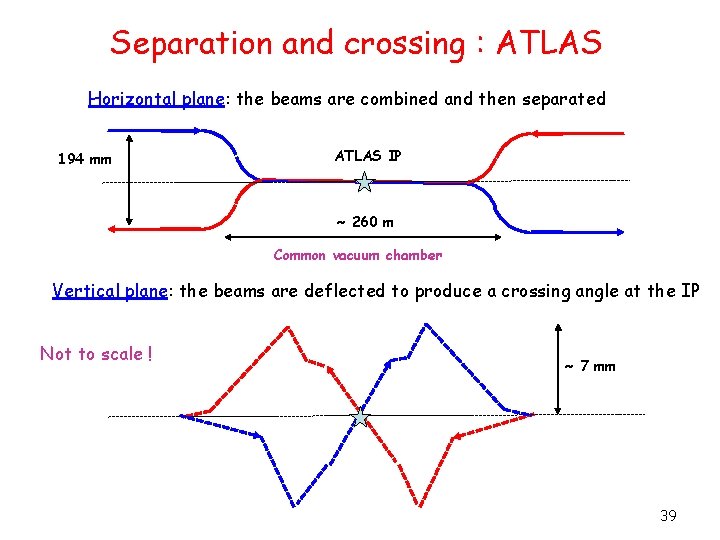
Separation and crossing : ATLAS Horizontal plane: the beams are combined and then separated 194 mm ATLAS IP ~ 260 m Common vacuum chamber Vertical plane: the beams are deflected to produce a crossing angle at the IP Not to scale ! ~ 7 mm 39
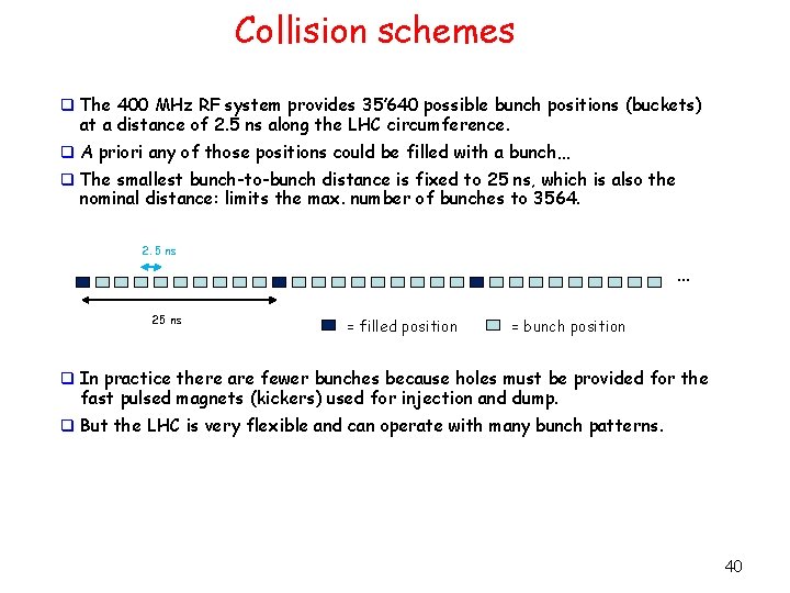
Collision schemes q The 400 MHz RF system provides 35’ 640 possible bunch positions (buckets) at a distance of 2. 5 ns along the LHC circumference. q A priori any of those positions could be filled with a bunch… q The smallest bunch-to-bunch distance is fixed to 25 ns, which is also the nominal distance: limits the max. number of bunches to 3564. 2. 5 ns 25 ns … = filled position = bunch position q In practice there are fewer bunches because holes must be provided for the fast pulsed magnets (kickers) used for injection and dump. q But the LHC is very flexible and can operate with many bunch patterns. 40
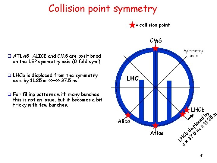
Collision point symmetry = collision point CMS Symmetry axis q ATLAS, ALICE and CMS are positioned on the LEP symmetry axis (8 fold sym. ) q LHCb is displaced from the symmetry axis by 11. 25 m <<-->> 37. 5 ns. LHC q For filling patterns with many bunches this is not an issue, but it becomes a bit tricky with few bunches. LHCb Alice Atlas by 5 m ed 1. 2 c la = 1 p s di ns Cb 7. 5 LH x 3 c 41
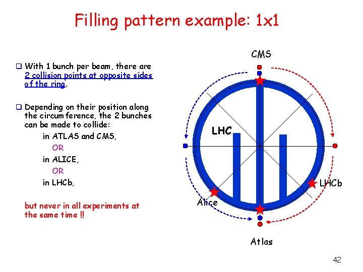
Filling pattern example: 1 x 1 CMS q With 1 bunch per beam, there are 2 collision points at opposite sides of the ring. q Depending on their position along the circumference, the 2 bunches can be made to collide: in ATLAS and CMS, OR in ALICE, OR in LHCb, but never in all experiments at the same time !! LHCb Alice Atlas 42
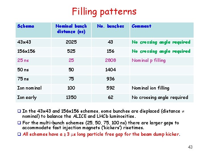
Filling patterns Schema Nominal bunch distance (ns) No. bunches 2025 43 No crossing angle required 525 156 No crossing angle required 25 ns 25 2808 50 ns 50 1404 75 ns 75 936 Ion nominal 100 592 1350 62 43 x 43 156 x 156 Ion early Comment Nominal p filling Nominal ion filling No crossing angle required q In the 43 x 43 and 156 x 156 schemes, some bunches are displaced (distance nominal) to balance the ALICE and LHCb luminosities. q For the multi-bunch schemes (25, 50, 75, 100 ns) there are larger gaps to accommodate fast injection magnets (‘kickers’) risetimes. q All schemes have a ≥ 3 s long particle free gap for the beam dump kicker. 43
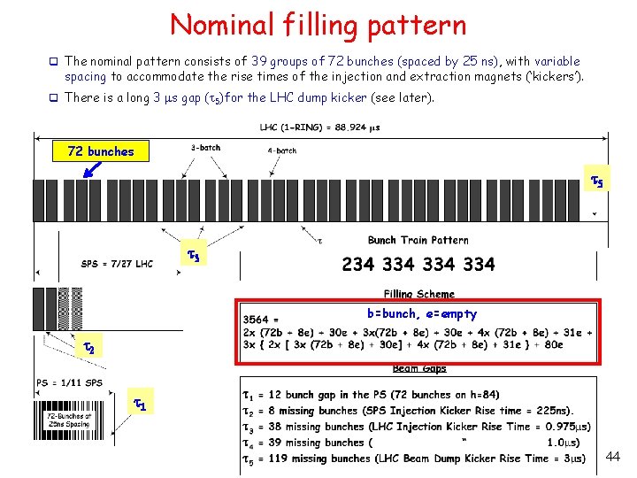
Nominal filling pattern q The nominal pattern consists of 39 groups of 72 bunches (spaced by 25 ns), with variable spacing to accommodate the rise times of the injection and extraction magnets (‘kickers’). q There is a long 3 s gap (t 5)for the LHC dump kicker (see later). 72 bunches t 5 t 3 b=bunch, e=empty t 2 t 1 44
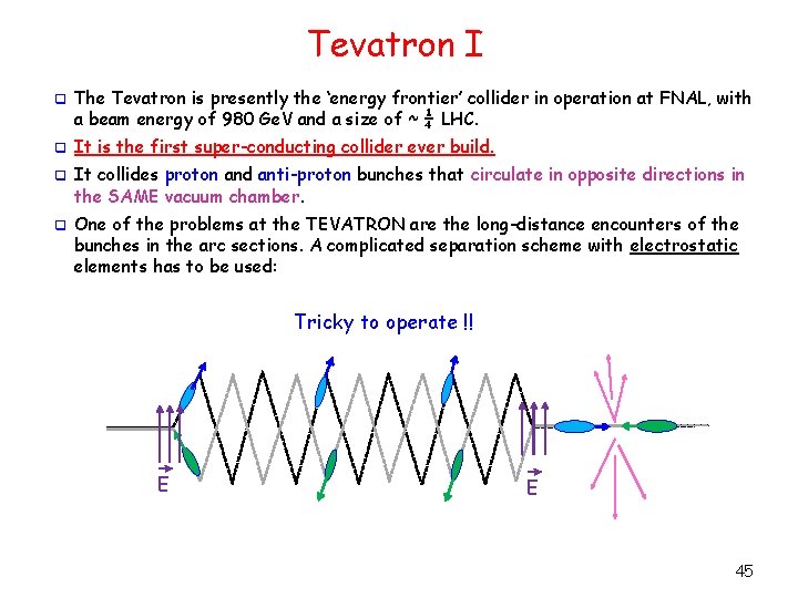
Tevatron I q The Tevatron is presently the ‘energy frontier’ collider in operation at FNAL, with a beam energy of 980 Ge. V and a size of ~ ¼ LHC. q It is the first super-conducting collider ever build. q It collides proton and anti-proton bunches that circulate in opposite directions in the SAME vacuum chamber. q One of the problems at the TEVATRON are the long-distance encounters of the bunches in the arc sections. A complicated separation scheme with electrostatic elements has to be used: Tricky to operate !! E E 45
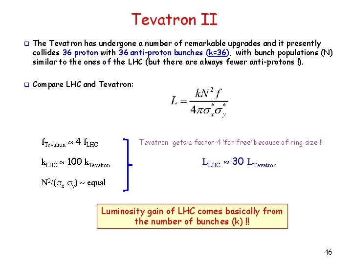
Tevatron II q The Tevatron has undergone a number of remarkable upgrades and it presently collides 36 proton with 36 anti-proton bunches (k=36), with bunch populations (N) similar to the ones of the LHC (but there always fewer anti-protons !). q Compare LHC and Tevatron: f. Tevatron 4 f. LHC Tevatron gets a factor 4 ‘for free’ because of ring size !! k. LHC 100 k. Tevatron LLHC 30 LTevatron N 2/(sx sy) ~ equal Luminosity gain of LHC comes basically from the number of bunches (k) !! 46
- Slides: 46