The Islamic University of Gaza Faculty of Engineering


- Slides: 17
ﺑﺴﻢ ﺍﻟﻠﻪ ﺍﻟﺮﺣﻤﻦ ﺍﻟﺮﺣﻴﻢ The Islamic University of Gaza Faculty of Engineering Electrical Engineering Department POWER ELECTRONICS EELE 5450 — Summer 2012 Instructor: Eng. Jalal Al Roumy Lecture 21
HALF-CONTROLLED BRIDGE WITH RESONANT LOAD If the resonance is to continue for most of the half-cycle in order to reduce the current harmonic content, the value of 1/a = t, the time constant, must be a significant part of the half-cycle period.
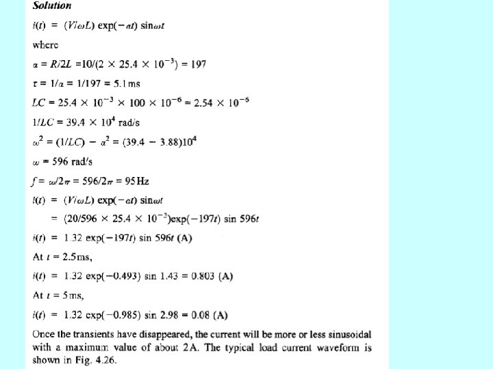
HALF-CONTROLLED BRIDGE WITH RESONANT LOAD Example
HALF-CONTROLLED BRIDGE WITH RESONANT LOAD Example
THREE-PHASE BRIDGE INVERTERS A full-bridge three-phase BJT inverter is shown. The load is a balanced star connection of pure resistors. If the load was inductive, feedback diodes would be connected across each switch; these could be built into the switch module. In this type of inverter, two or three switches could be conducting simultaneously.
Two switches conducting The conducting sequence is as follows (each device conducts for a 120 o period):
Two conducting devices- line voltage and current Values of line voltage and line (also phase) current for 60 o intervals are shown, from which the waveforms are constructed. The other two lines have identical values, displaced mutually by 120 o
Two conducting devices- line voltage and current Values of line voltage and line (also phase) current for 60 o intervals are shown, from which the waveforms are constructed. The other two lines have identical values, displaced mutually by 120 o
Two conducting devices- line voltage and current
Two conducting devices- line voltage and current
Three switches conducting The conducting sequence is as follows (each device conducts for a 180 o period):
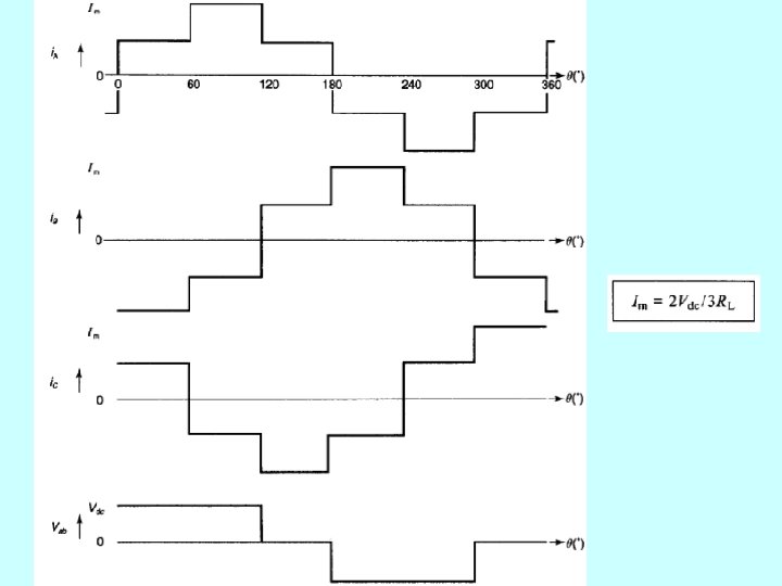
Three conducting devices- line voltage and current Values of line voltage and line (also phase) current for 60 o intervals are shown, from which the waveforms are constructed. The other two lines have identical values, displaced mutually by 120 o
Three conducting devices- line voltage and current Values of line voltage and line (also phase) current for 60 o intervals are shown, from which the waveforms are constructed. The other two lines have identical values, displaced mutually by 120 o
Comparing rms line currents
Comparing rms line currents End of Lecture