The ILD detector Design optimization and TPC RD


 and LCD (mainly")


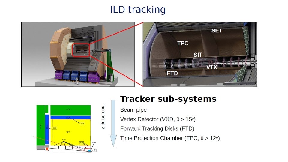


-x(track) Z=20 cm,")


- Slides: 22
The ILD detector: Design optimization and TPC R&D Paul Colas
The ILD concept • Based on Particle Flow: reconstruct the event by matching calorimeter objects with charged tracks (use the most precise E-p determination, avoid double count between tracks and E objects • Continuous tracking (TPC) and highly segmented calorimeters • Optimize jet energy resolution. vs. B, RTPC , ECAL cell size : 3. 5 T, 1. 7 m or 1. 4 m, 1 cm or less (MIP subtraction) • Vertex detector for b and c hadron reconstruction (jet charge) : 4 µm resolution
n Costing El e ec oj ag m ct ro Pr n tio nt ra nd la r to ec 10 e 0 et 20 m x. D 40 r( ce rte EU to ec Ve 50 Ti et ck in g. D Region of Origin . . . Ch ne am tic be Ca Ha r lo dr rim on ic et er Ca Fo lo rw r im ar d et M De er uo te n ct Sy or st em (c So al or ftw im So ar et ftw e ( Sim ry) ar e ul (R at ec io on n) st M ru ac ct Yo io hi n ke ne /M ) De Ov te er ag ct al ne l. D or t et In te ec rfa to Ph r. I ce Ph y n s ys te ics g ra An An tio al al n y s ys is is (H (n igg on Ph s) -H ys igg ics s. S An M al ) ys i s Da (B SM ta Ac ) qu isi tio n Ob se rv er Tr a AS ico AM Sil The ILD Group Currently 68 groups signed up ILD activities matrix 25 20 15 10 30 5 0
The ILD Organization Born from the fusion of GLD (mainly Asian) and LCD (mainly EU) LOI in March 2009, ‘Detector Baseline Document’ in 2013 One spoke (Ties Behnke, elected in 2015) One deputy spoke (Kiyotomo Kawagoe, nominated in 2016) An Institute Assembly (68 members, one per institute) An Executive Team A Technical Board, chaired by the Technical Coordinator (Claude Vallée nominated in 2016) • A Physics Group (Physics Coordinator Keisuke Fujii) • A Software Group (Software Coordinator Frank Gaede) • •
The ILD Technical Organization
TPC Readout Technologies MPGDs suffer less from Ex. B effects than MWPCs. They require less heavy mechanics. Panels with each technology have been made and tested. European GEMs Micromegas Standard kapton triple GEM with ceramic spacers Mesh on top of a charge-dispersing resistive anode Grid. Pix Asian GEMs Integrated grid on 55 µ digital pixels
TPC R&D: The LCTPC collaboration and the DESY test setup All the TPC R&D is gathered. www. lctpc. org The collaboration shares a test facility (Field cage, magnet, endplate, cosmic-ray trigger, ancillaries) Allows testing/comparing several technologies/ideas with cost-awareness
Beam and cosmic-ray tests Beam test in DESY magnet Cosmic-ray test at Saclay
Charge spreading by resistive foil Resistive coating on top of an insulator: Continuous RC network which spreads the charge: improves position sensitivity M. Dixit, A. Rankin, NIM A 566 (2006) 28 Various resistive coatings have been tried: Carbon-loaded Kapton (CLK), Diamond-like Carbon (DLC) and resistive ink (3 -5 M /sq) In addition the resistive foil suppresses sparks.
Charge spreading by resistive foil Gaussian spreading as a function of time with sr = sqrt(2 t/RC) t~shaping~few 100 ns RC = 180 R(M ) /(d/175µ) ns/mm² For R= 2 Mohm/sq, shaping 200 ns, 200 µ insulation in addition to the 50 µm kapton, one obtains sigma = 1. 3 mm (For 0. 2 Mohm/sq, we would have sigma= 3. 16 mm) M. Dixit, A. Rankin, NIM A 566 (2006) 28
Pad response Relative fraction of ‘charge’ seen by the pad, vs x(pad)-x(track) Z=20 cm, 200 ns shaping 24 rows x 72 columns of 3 x 6. 8 mm² pads x(pad) – x(track) (mm) 03/04/2018 13
ENCAPSULATED RESISTIVE ANODE DESIGN Spreading : Resistive layer connected to the guard ring with 28 03/04/2018 14
Results on resolution All pad TPC technologies give similar results (but with 3 mm pads for MM and 1. 2 mm pads for GEMs) 28/02/2017 Paul Colas - A TPC for ILC - INSTR 17 15
Results on resolution All pad TPC technologies give similar results (but with 3 mm pads for MM and 1. 2 mm pads for GEMs) 28/02/2017 Paul Colas - A TPC for ILC - INSTR 17 16
d. E/dx resolution of a resistive-anode TPC S. Voronov, M. Zito, PC OK for T 2 K 2 OK for ILD TPC : 5. 0% 03/04/2018 17
TPC design and integration : electronics integration D. Calvet et al. , IEEE trans.
TPC design and integration : mechanical integration Deformations under weight and inner pressure M. Carty, P. Manil et al. Resuming : Zhihong Sun et al.
TPC design and integration : 2 -phase CO 2 cooling Advantages: Specific heat 4 x water Latent heat for evaporation : 80 x water Boiling point at room temperature at 60 bar Inexplosive, non-conductive, vapors instantly at 1 atm. Tested in our test beam in 2014 and 2015
Cables, services, power consumption, … All details are written in a TPC Interface Control Document. Serious issues from push-pull operation. Ion back-flow, Gating IBF naturally suppressed in Micromegas. However a gating might be necessary, under study. One possibility demonstrated: large opening GEM, could be integrated to the modules.
Conclusions The ILD collaboration is coming to life Proof-of-principle of a Micromegas TPC done (GEMs have similar performances, the difference will be in complexity/reliability) Getting ready for the technology choice (S. Ganjour, K. Fujii et al. , TYL) Solutions for integration demonstrated, but still lots of studies in progress to make the detector a reality ILD members from Irfu: ATTIE David; BERRIAUD Christophe; Besancon Marc; COLAS Paul; FOURCHES Nicolas; GANJOUR Serguei; Giomataris Ioannis; NAPOLY Olivier; SHARYY Viatcheslav; TITOV Maksym; Tuchming Boris;