
the Globalstar System and evolutionary paths towards 3
the Globalstar System and evolutionary paths towards 3 G SCHOOL ON DIGITAL AND MULTIMEDIA COMMUNICATIONS USING TERRESTRIAL AND SATELLITE RADIO LINKS 27 th February 2001 Satellite Personal Communications Systems (S-PCS): TELIT MOBILE TERMINALS Giovanni De Maio Telit Mobile Terminals S. p. A. Project Manager - System Engineering Satellite User Terminal Division Via Vitorchiano, 81 - Rome giovanni. demaio@telital. com TELIT GROUP Industries for Telecommunications 1
Globalstar System Overview TELIT GROUP Industries for Telecommunications 2

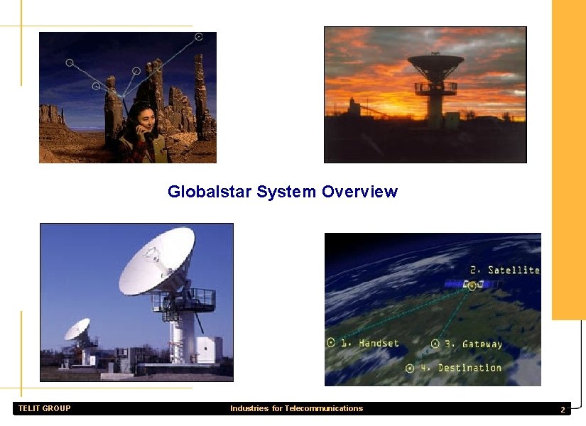
Globalstar service aspects Globalstar allows access to the terrestrial networks, both fixed and mobile, interworking with them in a complementary way. In areas not covered by the terrestrial networks, the Globalstar Terminal can be set to switch automatically from the terrestrial to the satellite mode. Globalstar System Overview Globalstar is a system that provide digital telephony with a global coverage, by means of a satellite constellation working in a Low Earth Orbit (LEO). The system is designed in order to maximise coverage in the temperate areas. TELIT GROUP Industries for Telecommunications 3
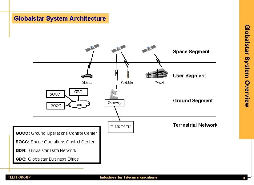
Globalstar System Architecture User Segment Mobile SOCC GOCC Portable Fixed GBO GDN Gateway PLMN/PSTN Ground Segment Globalstar System Overview Space Segment Terrestrial Network GOCC: Ground Operations Control Center SOCC: Space Operations Control Center GDN: Globalstar Data Network GBO: Globalstar Business Office TELIT GROUP Industries for Telecommunications 4
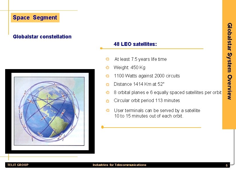
Space Segment 48 LEO satellites: At least 7. 5 years life time Weight: 450 Kg 1100 Watts against 2000 circuits Distance 1414 Km at 52° 8 orbital planes e 6 equally spaced satellites per orbit Circular orbit period 113 minutes Globalstar System Overview Globalstar constellation User terminals can be served by a satellite 10 to 15 minutes out of each orbit. TELIT GROUP Industries for Telecommunications 5
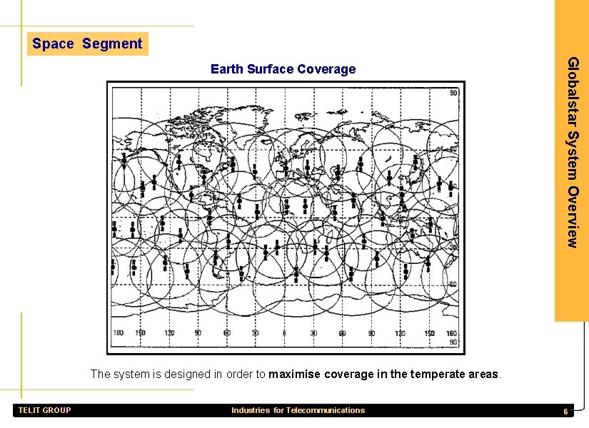
Space Segment Globalstar System Overview Earth Surface Coverage The system is designed in order to maximise coverage in the temperate areas. TELIT GROUP Industries for Telecommunications 6
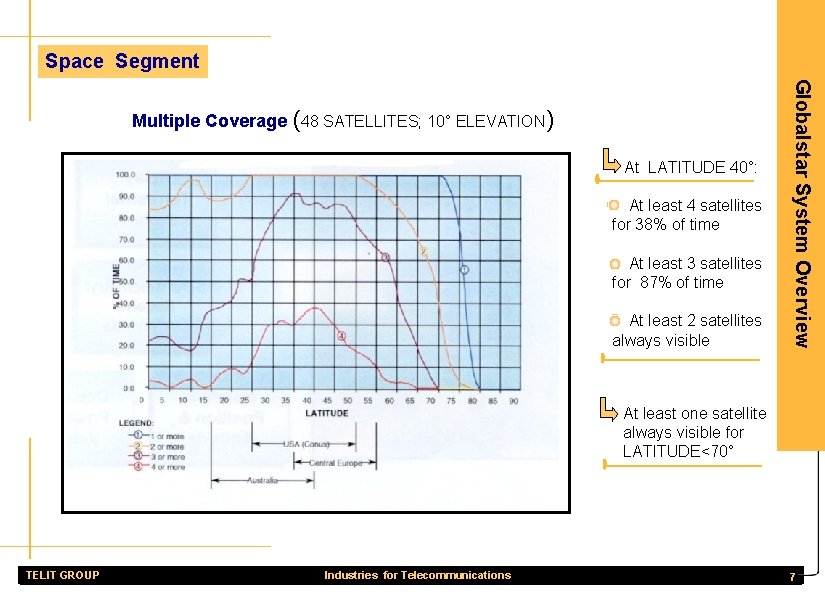
Space Segment At LATITUDE 40°: · At least 4 satellites for 38% of time · At least 3 satellites for 87% of time · At least 2 satellites always visible Globalstar System Overview Multiple Coverage (48 SATELLITES; 10° ELEVATION) At least one satellite always visible for LATITUDE<70° TELIT GROUP Industries for Telecommunications 7
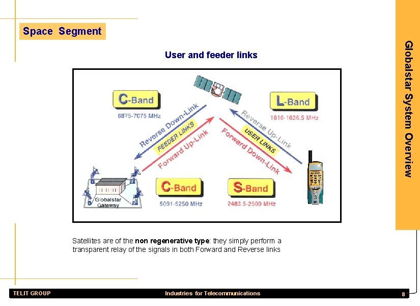
Space Segment immagini Globalstar System Overview User and feeder links immagini Satellites are of the non regenerative type: they simply perform a transparent relay of the signals in both Forward and Reverse links TELIT GROUP Industries for Telecommunications 8
Space Segment Industries for Telecommunications Globalstar System Overview TELIT GROUP Frequency channels 9
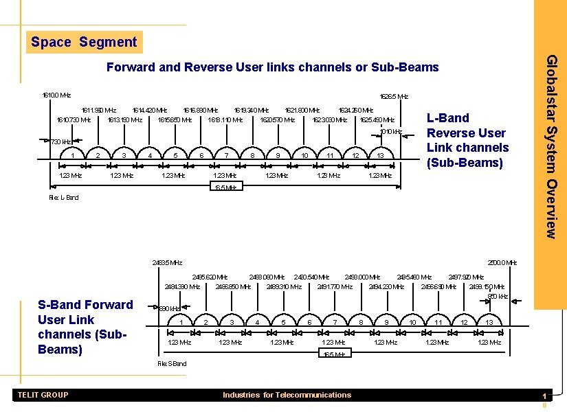
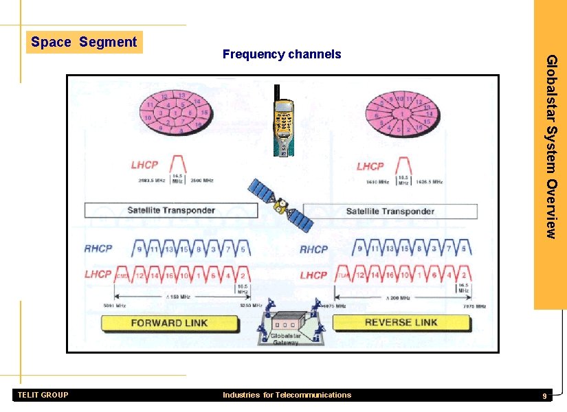
Space Segment 1610. 0 MHz 1626. 5 MHz 1611. 960 MHz 1614. 420 MHz 1616. 880 MHz 1619. 340 MHz 1621. 800 MHz 1624. 260 MHz 1610. 730 MHz 1613. 190 MHz 1615. 650 MHz 1618. 110 MHz 1620. 570 MHz 1623. 030 MHz 1625. 490 MHz L-Band Reverse User Link channels (Sub-Beams) 1010 k. Hz 730 k. Hz 1 1. 23 MHz 2 3 1. 23 MHz 4 5 6 7 1. 23 MHz 8 9 1. 23 MHz 10 1. 23 MHz 11 12 13 1. 23 MHz 16. 5 MHz File: L- Band 2483. 5 MHz S-Band Forward User Link channels (Sub. Beams) Globalstar System Overview Forward and Reverse User links channels or Sub-Beams 2500. 0 MHz 2485. 620 MHz 2488. 080 MHz 2490. 540 MHz 2493. 000 MHz 2495. 460 MHz 2497. 920 MHz 2484. 390 MHz 2486. 850 MHz 2489. 310 MHz 2491. 770 MHz 2494. 230 MHz 2496. 690 MHz 2499. 150 MHz 850 k. Hz 890 k. Hz 1 1. 23 MHz 2 3 1. 23 MHz 4 5 1. 23 MHz 6 7 1. 23 MHz 8 9 1. 23 MHz 10 11 1. 23 MHz 12 13 1. 23 MHz 16. 5 MHz File: S-Band TELIT GROUP Industries for Telecommunications 1 0

Space Segment Sub-Beams to Gateways Assignment Globalstar System Overview Overlapping Beams will transmit Sub-Beams for both Gateways TELIT GROUP Industries for Telecommunications 1 1

Space Segment Globalstar Air Interface Channels u provides system access information for registering UT’s u lets a phone know that a call is coming in or that there is a message in voice mail u for SMS u to reply to a UT trying to place a call, for handoff messaging when not in a call ACCESS: slotted random access channel for call originations, responses to pages and registrations PILOT: unmodulated DS SS signal transmitted by the Gateway (employed to acquire the timing, as phase reference for demodulation and to handoff) SYNC: channel carrying a repeating message for terminal synchronization TELIT GROUP Globalstar System Overview PAGING: TRAFFIC: communication path between a UT and a Gateway, which implies a Forward and a Reverse Traffic Channel pair; for voice, data, signaling (when in a call) Industries for Telecommunications 1 2

Space Segment Globalstar System Overview Example of a Forward CDMA Channel The above example shows a particular assignment of the overall 128 channels (codes) within a 1. 23 MHz Forward Channel to Pilot, Sync, Paging and Traffic functionalities TELIT GROUP Industries for Telecommunications 1 3
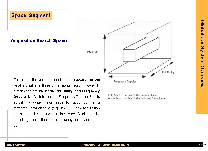
Space Segment The acquisition process consists of a research of the pilot signal in a three dimensional search space: its Globalstar System Overview Acquisition Search Space dimensions are PN Code, PN Timing and Frequency Doppler Shift. Note that the Frequency Doppler Shift is actually a quite minor issue for acquisition in a terrestrial environment (e. g. IS-95). Less acquisition times could be achieved in the Warm Start case by exploiting information acquired during the previous start up. TELIT GROUP Industries for Telecommunications 1 4
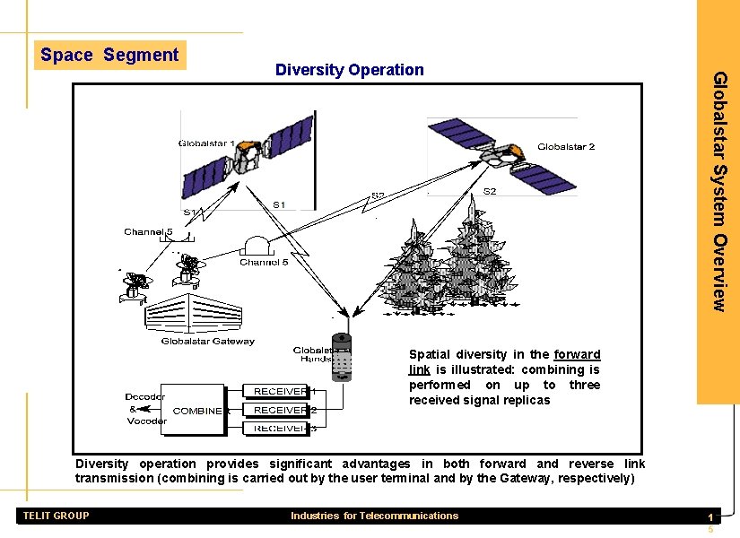
Space Segment Globalstar System Overview Diversity Operation Spatial diversity in the forward link is illustrated: combining is performed on up to three received signal replicas Diversity operation provides significant advantages in both forward and reverse link transmission (combining is carried out by the user terminal and by the Gateway, respectively) TELIT GROUP Industries for Telecommunications 1 5
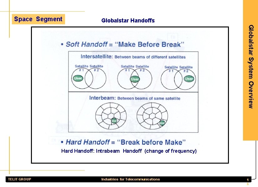
Space Segment Globalstar Handoffs Globalstar System Overview Hard Handoff: Intrabeam Handoff (change of frequency) TELIT GROUP Industries for Telecommunications 1 6
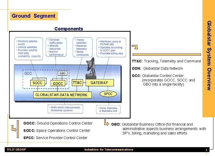
Ground Segment Globalstar System Overview Components TT&C: Tracking, Telemetry and Command GDN: Globalstar Data Network GCC: Globalstar Control Center (incorporates GOCC, SOCC and GBO into a single facility) GOCC: Ground Operations Control Center SOCC: Space Operations Control Center GBO: Globalstar Business Office (for financial and administrative aspects: business arrangements with SP’s, billing, marketing and sales efforts SPCC: Service Provider Control Center TELIT GROUP Industries for Telecommunications 1 7
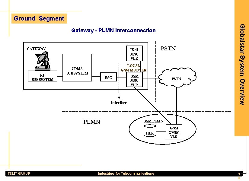
Ground Segment GATEWAY RF SUBSYSTEM PSTN IS-41 MSC VLR LOCAL GSM MSC/VLR CDMA SUBSYSTEM BSC GSM MSC VLR PSTN A Interface PLMN GSM PLMN HLR TELIT GROUP Globalstar System Overview Gateway - PLMN Interconnection Industries for Telecommunications GSM GMSC VLR 1 8
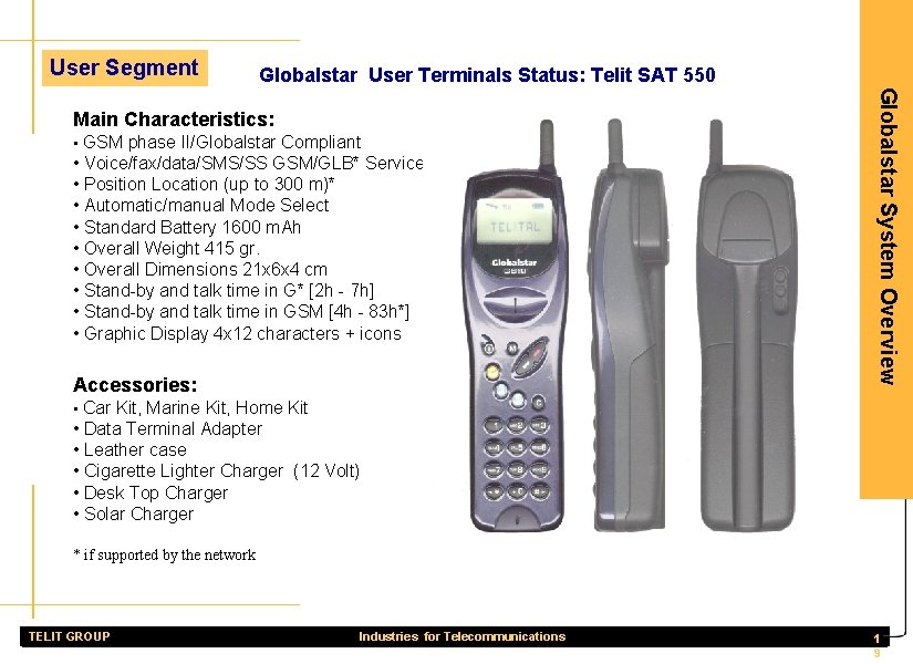
User Segment Globalstar User Terminals Status: Telit SAT 550 • GSM phase II/Globalstar Compliant • Voice/fax/data/SMS/SS GSM/GLB* Services • Position Location (up to 300 m)* • Automatic/manual Mode Select • Standard Battery 1600 m. Ah • Overall Weight 415 gr. • Overall Dimensions 21 x 6 x 4 cm • Stand-by and talk time in G* [2 h - 7 h] • Stand-by and talk time in GSM [4 h - 83 h*] • Graphic Display 4 x 12 characters + icons Accessories: Globalstar System Overview Main Characteristics: • Car Kit, Marine Kit, Home Kit • Data Terminal Adapter • Leather case • Cigarette Lighter Charger (12 Volt) • Desk Top Charger • Solar Charger * if supported by the network TELIT GROUP Industries for Telecommunications 1 9
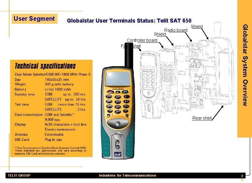
User Segment Globalstar User Terminals Status: Telit SAT 650 Shield Globalstar System Overview Radio board Shield Controller board Front shell Rear shell TELIT GROUP Industries for Telecommunications 2 0
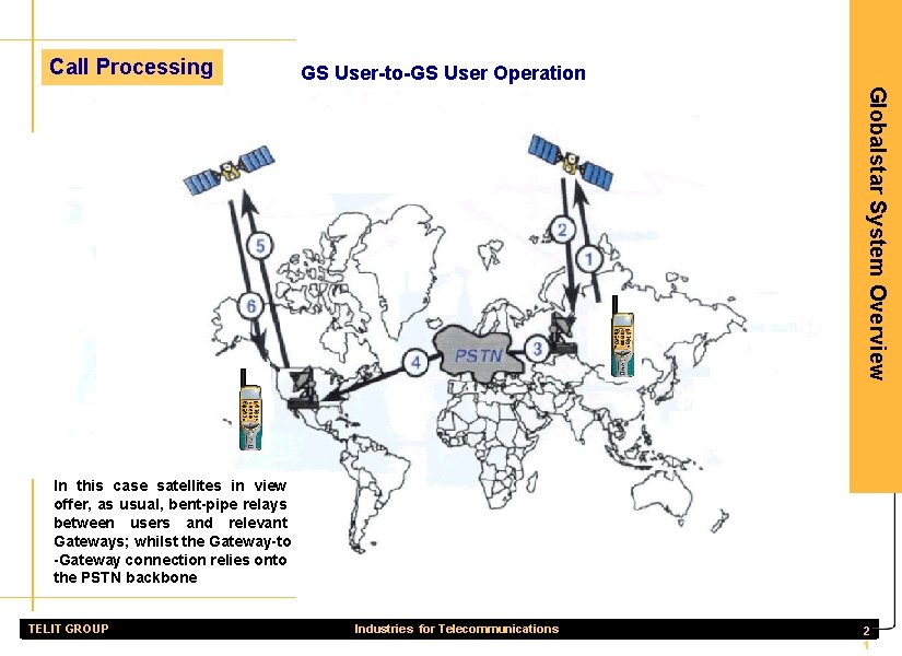
Call Processing GS User-to-GS User Operation Globalstar System Overview In this case satellites in view offer, as usual, bent-pipe relays between users and relevant Gateways; whilst the Gateway-to -Gateway connection relies onto the PSTN backbone TELIT GROUP Industries for Telecommunications 2 1
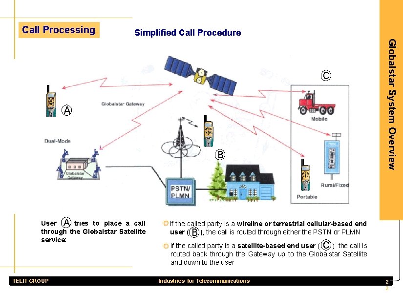
Call Processing Simplified Call Procedure A B User A tries to place a call through the Globalstar Satellite service: TELIT GROUP Globalstar System Overview C if the called party is a wireline or terrestrial cellular-based end user ( B ), the call is routed through either the PSTN or PLMN if the called party is a satellite-based end user ( C ) the call is routed back through the Gateway up to the Globalstar Satellite and down to the user Industries for Telecommunications 2 2
3 G S-PCS: The Next Step TELIT GROUP Industries for Telecommunications 2 3
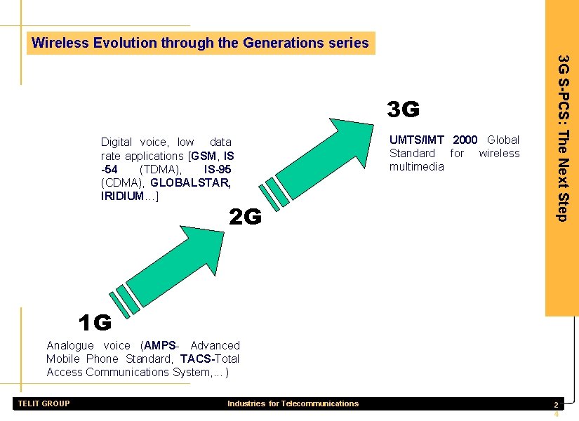
Wireless Evolution through the Generations series Digital voice, low data rate applications [GSM, IS -54 (TDMA), IS-95 (CDMA), GLOBALSTAR, IRIDIUM…] 2 G UMTS/IMT 2000 Global Standard for wireless multimedia 3 G S-PCS: The Next Step 3 G 1 G Analogue voice (AMPS- Advanced Mobile Phone Standard, TACS-Total Access Communications System, . . . ) TELIT GROUP Industries for Telecommunications 2 4
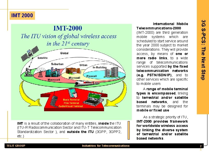
IMT 2000 3 G S-PCS: The Next Step International Mobile Telecommunications-2000 (IMT-2000) are third generation mobile systems which are scheduled to start service around the year 2000 subject to market considerations. They will provide access, by means of one or more radio links, to a wide range of telecommunications services supported by the fixed telecommunication networks (e. g. PSTN/ISDN/IP), and to other services which are specific to mobile users A range of mobile terminal types is encompassed, linking to terrestrial and/or satellite based networks, and the terminals may be designed for mobile or fixed use IMT is a result of the collaboration of many entities, inside the ITU (ITU-R Radiocommunication Sector and ITU-T Telecommunication Standardization Sector ), and outside the ITU (3 GPP, 3 GPP 2, etc. ) TELIT GROUP Industries for Telecommunications As a strategic priority of ITU, IMT-2000 provides framework for worldwide wireless access by linking the diverse system of terrestrial and/or satellite based networks. 2 5
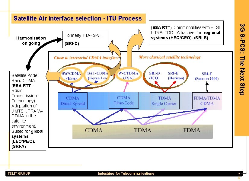
Satellite Air interface selection - ITU Process Formerly TTA- SAT. (SRI-C) Satellite Wide Band CDMA (ESA RTTRadio Transmission Technology). Adaptation of UMTS UTRA WCDMA to the satellite environment. Suited for global systems (LEO/MEO). (SRI-A) TELIT GROUP Industries for Telecommunications 3 G S-PCS: The Next Step Harmonization on going (ESA RTT) Commonalities with ETSI UTRA TDD. Attractive for regional systems (HEO/GEO). (SRI-B) 2 6
First set of ETSI Technical Specs approved (1/2) 3 G S-PCS: The Next Step S-UMTS stands for the Satellite component of the Universal Mobile Telecommunication System. S-UMTS systems will complement the terrestrial UMTS (T-UMTS) and inter-work with other IMT-2000 family members through the UMTS core network. S-UMTS will be used to deliver 3 rd generation mobile satellite services (MSS) utilizing either low (LEO) or medium (MEO) earth orbiting, or geostationary (GEO) satellite(s). S-UMTS systems are based on terrestrial 3 GPP specifications and will support access to GSM/UMTS core networks. Due to the differences between terrestrial and satellite channel characteristics, some modifications to the terrestrial UMTS (TUMTS) standards are necessary. Some specifications are directly applicable, whereas others are applicable with modifications. Similarly, some T-UMTS specifications do not apply, whilst some S-UMTS specifications have no corresponding T-UMTS specification. TELIT GROUP Industries for Telecommunications 2 7
First set of ETSI Technical Specs approved (2/2) Part 1: Physical channels and mapping of transport channels into physical channels (S-UMTS-A 25. 211) Part 2: Multiplexing and channel coding (S-UMTS-A 25. 212) Part 3: Spreading and modulation (S-UMTS-A 25. 213) 3 G S-PCS: The Next Step Satellite Component of UMTS/IMT 2000; A-family; Part 4: Physical layer procedures (S-UMTS-A 25. 214) TELIT GROUP Industries for Telecommunications 2 8
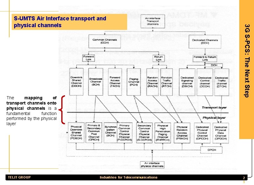
The mapping of transport channels onto physical channels is a fundamental function performed by the physical layer TELIT GROUP Industries for Telecommunications 3 G S-PCS: The Next Step S-UMTS Air Interface transport and physical channels 2 9
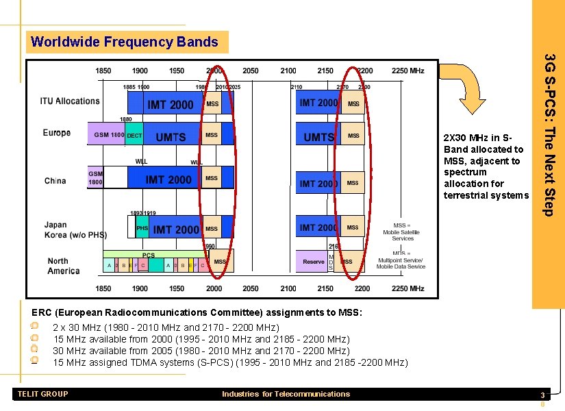
Worldwide Frequency Bands 3 G S-PCS: The Next Step 2 X 30 MHz in SBand allocated to MSS, adjacent to spectrum allocation for terrestrial systems ERC (European Radiocommunications Committee) assignments to MSS: – – 2 x 30 MHz (1980 - 2010 MHz and 2170 - 2200 MHz) 15 MHz available from 2000 (1995 - 2010 MHz and 2185 - 2200 MHz) 30 MHz available from 2005 (1980 - 2010 MHz and 2170 - 2200 MHz) 15 MHz assigned TDMA systems (S-PCS) (1995 - 2010 MHz and 2185 -2200 MHz) TELIT GROUP Industries for Telecommunications 3 0
Spectrum Needs Terrestrial PCS are competing for spectrum allocation WRC 2000 (2000 World Radiocommunications Conference) postponed a decision on satellite phone frequencies until 2003, which means that 3 G S-PCS: The Next Step More bandwidth requested before 2003 a viable satellite consortium needs to be established or else the already allocated spectrum will be lost and available in favour of TUMTS TELIT GROUP Industries for Telecommunications 3 1
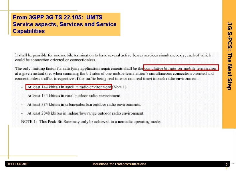
TELIT GROUP Industries for Telecommunications 3 G S-PCS: The Next Step From 3 GPP 3 G TS 22. 105: UMTS Service aspects, Services and Service Capabilities 3 2
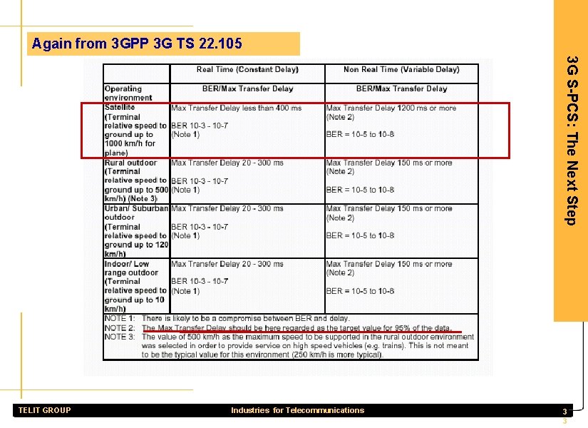
Again from 3 GPP 3 G TS 22. 105 3 G S-PCS: The Next Step TELIT GROUP Industries for Telecommunications 3 3
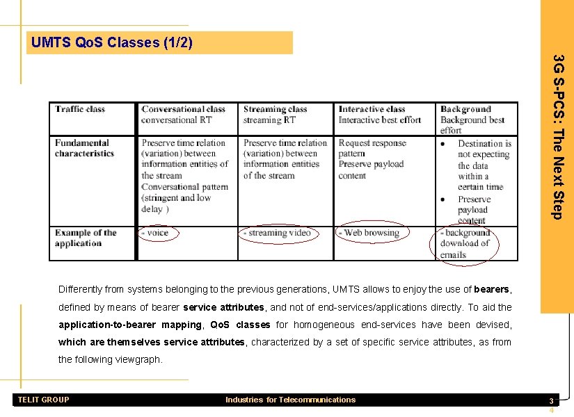
UMTS Qo. S Classes (1/2) 3 G S-PCS: The Next Step Differently from systems belonging to the previous generations, UMTS allows to enjoy the use of bearers, defined by means of bearer service attributes, and not of end-services/applications directly. To aid the application-to-bearer mapping, Qo. S classes for homogeneous end-services have been devised, which are themselves service attributes, characterized by a set of specific service attributes, as from the following viewgraph. TELIT GROUP Industries for Telecommunications 3 4
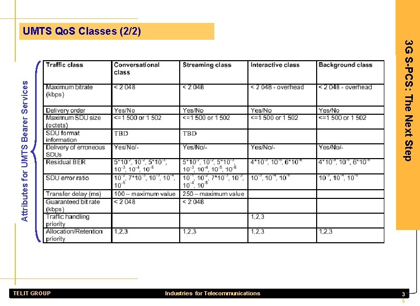
UMTS Qo. S Classes (2/2) Attributes for UMTS Bearer Services 3 G S-PCS: The Next Step TELIT GROUP Industries for Telecommunications 3 5
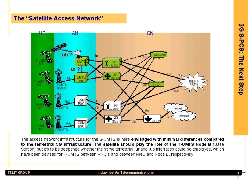
The “Satellite Access Network” 3 G S-PCS: The Next Step Iub ? Iur ? The access network infrastructure for the S-UMTS is here envisaged with minimal differences compared to the terrestrial 3 G infrastructure. The satellite should play the role of the T-UMTS Node B (Base Station) but it’s to be deepened whether the same terrestrial Iur and Iub interfaces could be employed, which have been devised for T-UMTS between RNC’s and between RNC and Node B, respectively. TELIT GROUP Industries for Telecommunications 3 6
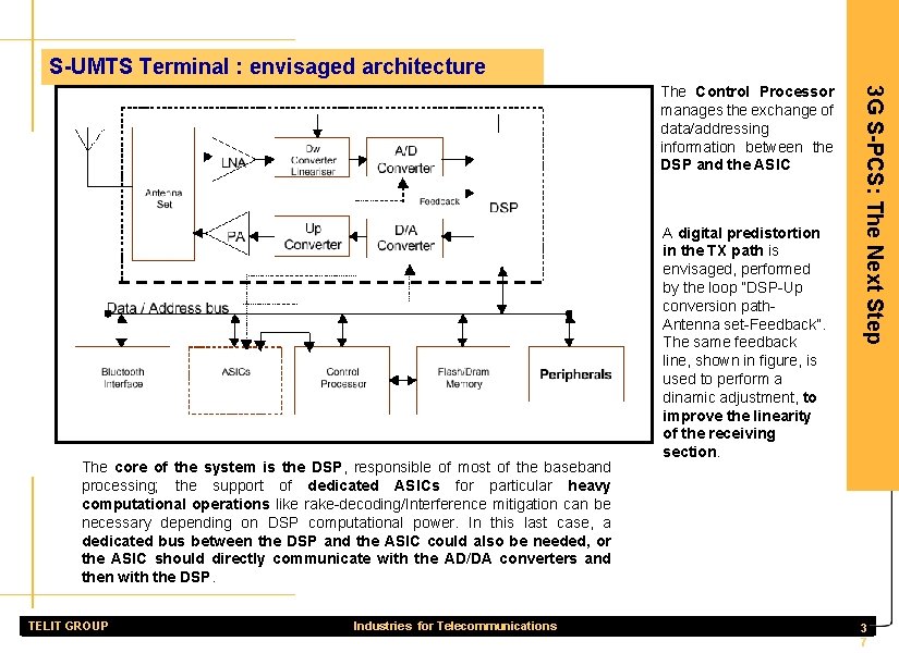
S-UMTS Terminal : envisaged architecture The core of the system is the DSP, responsible of most of the baseband processing; the support of dedicated ASICs for particular heavy computational operations like rake-decoding/Interference mitigation can be necessary depending on DSP computational power. In this last case, a dedicated bus between the DSP and the ASIC could also be needed, or the ASIC should directly communicate with the AD/DA converters and then with the DSP. TELIT GROUP Industries for Telecommunications A digital predistortion in the TX path is envisaged, performed by the loop “DSP-Up conversion path. Antenna set-Feedback”. The same feedback line, shown in figure, is used to perform a dinamic adjustment, to improve the linearity of the receiving section. 3 G S-PCS: The Next Step The Control Processor manages the exchange of data/addressing information between the DSP and the ASIC 3 7
- Slides: 37